CJ6UPSU7FPC1Notebook Computer
Dynabook Inc.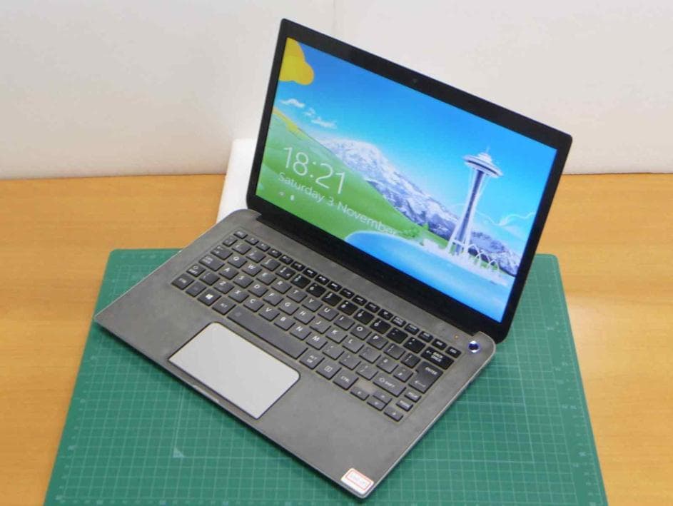
Click to zoom
Application Details
- Equipment Class
- DTS - Digital Transmission System
- Date of Grant
- Dec 25, 2012
- Application Purpose
- Original Equipment
- Date of Application
- Dec 24, 2012
- Equipment Note
- Notebook Computer
- Frequency Range
- 2402.00000000 - 2480.00000000
- Company
- Dynabook Inc.
- Country
- Japan
Documents & Files
Document Text
Text extracted from the exhibit documents filed with the FCC. Open a document above to read the original.
Users Manual
User's Manual Satellite U930/U930t series Table of Contents Chapter 1 TOSHIBA Legal, Regulatory and Safety Copyright, Disclaimer and Trademarks .............................................. 1-1 Regulatory Information ......................................................................... 1-2 Video Standard Notice .......................................................................... 1-3 OpenSSL Toolkit License Issues ......................................................... 1-3 ENERGY STAR® Program .................................................................... 1-7 Disposing of the computer and the computer's batteries ................. 1-7 General Precautions ............................................................................. 1-7 Safety Icons ......................................................................................... 1-10 Chapter 2 Getting Started Equipment checklist ............................................................................. 2-1 Conventions ........................................................................................... 2-1 Using your computer for the first time ................................................ 2-2 Turning off the power ............................................................................ 2-8 Chapter 3 The Grand Tour Front with the display closed ............................................................... 3-1 Left side .................................................................................................. 3-1 Right side ............................................................................................... 3-2 Back ........................................................................................................ 3-3 Underside ............................................................................................... 3-3 Front with the display open .................................................................. 3-4 Internal Hardware Components ........................................................... 3-7 Monitoring of power conditions ......................................................... 3-11 Chapter 4 Operating Basics Using the Touch Screen ....................................................................... 4-1 The Keyboard ......................................................................................... 4-2 Battery .................................................................................................... 4-4 Memory media ....................................................................................... 4-8 HDMI Device ......................................................................................... 4-12 Optional TOSHIBA Accessories ........................................................ 4-14 Sound System and Video mode ......................................................... 4-14 Chapter 5 Utilities and Advanced Usage Utilities and Applications ...................................................................... 5-1 Special features ..................................................................................... 5-4 User's Manualii TOSHIBA Password utility .................................................................... 5-6 TOSHIBA System Settings ................................................................... 5-8 USB Charge ............................................................................................ 5-9 Sleep and Music .................................................................................. 5-12 TOSHIBA Media Player by sMedio TrueLink+ .................................. 5-13 TOSHIBA PC Health Monitor .............................................................. 5-14 System Recovery ................................................................................ 5-15 Chapter 6 Troubleshooting Problem solving process ...................................................................... 6-1 Hardware and system checklist ........................................................... 6-4 TOSHIBA support ................................................................................ 6-14 Chapter 7 Appendix Specifications ........................................................................................ 7-1 AC Power Cord and Connectors .......................................................... 7-2 Information for Wireless Devices ........................................................ 7-3 Legal Footnotes ..................................................................................... 7-7 Glossary ............................................................................................... 7-10 Index User's Manualiii Chapter 1 TOSHIBA Legal, Regulatory and Safety This chapter states the Legal, regulatory and safety information applicable to TOSHIBA computers. Copyright, Disclaimer and Trademarks Copyright © 2012 by TOSHIBA Corporation. All rights reserved. Under the copyright laws, this manual cannot be reproduced in any form without the prior written permission of TOSHIBA. No patent liability is assumed, with respect to the use of the information contained herein. First edition December 2012 Copyright authority for music, movies, computer programs, databases and other intellectual property covered by copyright laws belongs to the author or to the copyright owner. Copyrighted material can be reproduced only for personal use or use within the home. Any other use beyond that stipulated above (including conversion to digital format, alteration, transfer of copied material and distribution on a network) without the permission of the copyright owner is a violation of copyright or author's rights and is subject to civil damages or criminal action. Please comply with copyright laws in making any reproduction from this manual. Disclaimer This manual has been validated and reviewed for accuracy. The instructions and descriptions it contains are accurate for your computer at the time…
Text truncated - open the document above for the full version.
External Photos
Top Bottom Left Right Front Rear Chain A (Main antenna) Chain B (Aux antenna) LCD open Chain A (Main antenna) Chain B (Aux antenna)
ID Label/Location Info
Confidential
Internal Photos
Bottom cover removed Module zoom up Module Top with shield Top without shield Bottom Antenna
RF Exposure Info
Test report No. : 33CE0267-SH-01-R03 Page : 2 of 57 Issued date : December 5, 2012 Revised date : December 25, 2012 FCC ID : CJ6UPSU7FPC1 UL Japan, Inc. Shonan EMC Lab. 1-22-3 Megumigaoka, Hiratsuka-shi, Kanagawa-ken, 259-1220 JAPAN Telephone: +81 463 50 6400 / Facsimile: +81 463 50 6401 CONTENTS PAGE SECTION 1: Customer information ....................................................................... 3 SECTION 2: Equipment under test (EUT) ............................................................. 3 SECTION 3: Test specification, procedures and results......................................... 4 3.1 Test specification ..................................................................................................... 4 3.2 Exposure limit ......................................................................................................... 4 3.3 Procedure ................................................................................................................. 4 3.4 Test location ............................................................................................................ 4 3.5 Confirmation for SAR testing................................................................................... 5 3.6 Confirmation after SAR testing ................................................................................ 6 3.7 Test setup of EUT and SAR measurement procedure ................................................ 6 SECTION 4: Operation of EUT during testing ...................................................... 7 SECTION 5: Uncertainty Assessment (SAR measurement)................................... 8 SECTION 6: Confirmation before testing............................................................... 9 SECTION 7: Measurement results .......................................................................... 11 Contents of appendixes APPENDIX 1: Photographs of test setup................................................................... 13 Appendix 1-1 Photograph of EUT and antenna position ................................................................. 13 Appendix 1-2 EUT and support equipment (for SAR test) .............................................................. 14 Appendix 1-3 Photograph of test setup ........................................................................................... 15 APPENDIX 2: SAR Measurement data..................................................................... 19 Appendix 2-1 Evaluation procedure ............................................................................................... 19 Appendix 2-2 Measurement data .................................................................................................... 23 APPENDIX 3: Test instruments................................................................................. 31 Appendix 3-1 Equipment used ....................................................................................................... 31 Appendix 3-2 Configuration and peripherals .................................................................................. 32 Appendix 3-3 Test system specification .......................................................................................... 33 Appendix 3-4 Simulated tissues composition .................................................................................. 34 Appendix 3-5 Simulated tissues parameter confirmation ................................................................ 34 Appendix 3-6 System check data .................................................................................................... 35 Appendix 3-7 System check measurement data .............................................................................. 36 Appendix 3-8 System check uncertainty ......................................................................................... 37 Appendix 3-9 Calibration certificate: Dipole (D2450V2) ................................................................ 38 Appendix 3-10 Calibration certificate: E-Field Probe (EX3DV4) ..................................................... 46 Appendix 3-11 References................................................................................................................ 57 REVISION HISTORY Revision Test report No.Date Page revisedContents Original 33CE0267-SH-01December 5, 2012-- 1 33CE0267-SH-01-R01 December 19, 20121, 4, 9, 12 Highest SAR value: Correction of errors 3.1 Add KDB 616217 / 6.1.1 Correction of errors / 7.1 Correction of errors 2 33CE0267-SH-01-R02 December 21, 20123, 4, 9, 12 2.1 Correction of errors / 3.1 Correction of errors / 6.1.1 Correction of errors 7.1 Add reason of exclusion test 3 33CE0267-SH-01-R03 December 25, 20121, 11, 12, Add highest sum of SAR(1g) value 7.1 Formattin g changes and Correction of errors / Add section 7.2 *. By issue of new revision report, the report of an old revision becomes invalid. Test report No. : 33CE0267-SH-01-R03 Page : 3 of 57 Issued date : December 5, 2012 Revised date : December 25, 2012 FCC ID : CJ6UPSU7FPC1 UL Japan, Inc. Shonan EMC Lab. 1-22-3 Megumigaoka, Hiratsuka-shi, Kanagawa-ken, 259-1220 JAPAN Telephone: +81 463 50 6400 / Facsimile: +81 463 50 6401 SECTION 1: Customer information Company Name Toshiba Corporation Brand Name TOSHIBA Address 2-9, Suehiro-Cho, Ome, Tokyo 198-8710 JAPAN Telephone Number +81-428-34-2403 Facsimile Number +81-428-30-7906 Contact Person Kazuya Fukushima SECTION 2: Equipment under test (EUT) 2.1 Identification of EUT (*.Main unit including antenna and RF module) Type of Equipment Laptop Computer Model Number Satellite U930 Serial Number XC125734H Condition of EUT Production prototype (*. Not for sale: This sample is equivalent to mass-produced items.) Receipt Date of Sample November 14, 2012 (*. No modification by the Lab.) Country of Mass-production China Rating DC19V Category Identified Portable device Feature of EUT The EUT is a laptop computer installed Wireless LAN and Blue…
Text truncated - open the document above for the full version.
RF Exposure Info
Test report No. : 33CE0267-SH-01-R03 Page : 19 of 57 Issued date : December 5, 2012 Revised date : December 25, 2012 FCC ID : CJ6UPSU7FPC1 UL Japan, Inc. Shonan EMC Lab. 1-22-3 Megumigaoka, Hiratsuka-shi, Kanagawa-ken, 259-1220 JAPAN Telephone: +81 463 50 6400 / Facsimile: +81 463 50 6401 APPENDIX 2: SAR Measurement data Appendix 2-1: Evaluation procedure The SAR evaluation was performed with the following procedure: Step 1: Measurement of the E-field at a fixed location above the central position of flat phantom was used as a reference value for assessing the power drop. Step 2: The SAR distribution at the exposed side of head or body position was measured at a distance of each device from the inner surface of the shell. The area covered the entire dimension of the antenna of EUT and suitable horizontal grid spacing of EUT. Based on these data, the area of the maximum absorption was determined by splines interpolation. Step 3: Around this point found in the Step 2 (area scan), a volume of 30mm(X axis)30mm(Y axis)30mm(Z axis) was assessed by measuring 777 points under 3GHz. And for any secondary peaks found in the Step2 which are within 2dB of maximum peak and not with this Step3 (Zoom scan) is repeated. On the basis of this data set, the spatial peak SAR value was evaluated under the following procedure: (1) The data at the surface were extrapolated, since the center of the dipoles is 1mm away from the tip of the probe and the distance between the surface and the lowest measuring point is 2mm. The extrapolation was based on a least square algorithm [4]. A polynomial of the fourth order was calculated through the points in z-axes. This polynomial was then used to evaluate the points between the surface and the probe tip. (2) The maximum interpolated value was searched with a straightforward algorithm. Around this maximum the SAR values averaged over the spatial volumes (1g or 10g) were computed by the 3D-Spline interpolation algorithm. The 3D-Spline is composed of three one-dimensional splines with the “Not a knot"-condition (in x, y and z-directions) [4], [5]. The volume was integrated with the trapezoidal-algorithm. One thousand points (101010) were interpolated to calculate the average. (3) All neighboring volumes were evaluated until no neighboring volume with a higher average value was found. Step 4: Re-measurement of the E-field at the same location as in Step 1 for the assessment of the power drift. Step 5: Repeat Step 1-Step 4 with other condition or/and setup of EUT. Test report No. : 33CE0267-SH-01-R03 Page : 20 of 57 Issued date : December 5, 2012 Revised date : December 25, 2012 FCC ID : CJ6UPSU7FPC1 UL Japan, Inc. Shonan EMC Lab. 1-22-3 Megumigaoka, Hiratsuka-shi, Kanagawa-ken, 259-1220 JAPAN Telephone: +81 463 50 6400 / Facsimile: +81 463 50 6401 Appendix 2-2: Measurement data Step 1: Worst position search(Chain A(Main antenna)) Step 1-1: Lap held(Bottom face)(separation distance: 0mm) / 2437MHz, 11b(1Mbps) Chain A(Main antenna) EUT: Satellite_U930; Type: Laptop PC; Serial: XC125734H Communication System: 802.11bgn; Frequency: 2437 MHz; Crest factor: 1.0 Medium: MSL2450; Medium parameters used: f = 2437 MHz; σ = 1.945 S/m; ε r = 50.527; ρ = 1000 kg/m 3 Measurement Standard: DASY5 (IEEE/IEC/ANSI C63.19-2007) DASY Configuration: -Probe: EX3DV4 - SN3679; ConvF(6.77, 6.77, 6.77); Calibrated: 2012/06/21; -Sensor-Surface: 2mm (Mechanical Surface Detection), z = 1.0, 31.0, 161.0 -Electronics: DAE4 Sn626; Calibrated: 2012/02/15 -Phantom: ELI v4.0; Type: QDOVA001BA; Serial: 1059; Phantom section: Flat Section -DASY52 52.8.2(969); SEMCAD X 14.6.6(6824) Lap held(Bottom face)/Touch(0mm)_11b(1Mbps)_Mid-Ch_main-ant/ Area Scan:135x360,15 (10x25x1): Measurement grid: dx=15mm, dy=15mm, Maximum value of SAR (measured) = 0.239 W/kg Area Scan:135x360,15 (91x241x1): Interpolated grid: dx=1.500 mm, dy=1.500 mm, Maximum value of SAR (interpolated) = 0.240 W/kg Z Scan;160,5 (1x1x33): Measurement grid: dx=20mm, dy=20mm, dz=5mm, Maximum value of SAR (measured) = 0.472 W/kg Zoom Scan:30x30x30,5-5-5 (7x7x7)/Cube 0: Measurement grid: dx=5mm, dy=5mm, dz=5mm, Reference Value = 11.380 V/m; Power Drift = 0.14 dB, Maximum value of SAR (measured) = 0.269 W/kg Peak SAR (extrapolated) = 0.371 mW/g SAR(1 g) = 0.182 mW/g; SAR(10 g) = 0.093 mW/g Remarks:*. Date tested: Date/Time: 2012/11/15; Tested by: Tomochika Sato; Tested place:No.7 shielded room, *.liquid depth: 153mm; Position: distance of EUT to phantom: 0mm (2mm to liquid); ambient: 24.0 deg.C. / 45 %RH, *.liquid temperature: 23.0(start)/23.0(end)/22.9(in check) deg.C.; *.White cubic: zoom scan area, Red cubic: big=SAR(10g )/small=SAR(1g) Test report No. : 33CE0267-SH-01-R03 Page : 21 of 57 Issued date : December 5, 2012 Revised date : December 25, 2012 FCC ID : CJ6UPSU7FPC1 UL Japan, Inc. Shonan EMC Lab. 1-22-3 Megumigaoka, Hiratsuka-shi, Kanagawa-ken, 259-1220 JAPAN Telephone: +81 463 50 6400 / Facsimile: +81 463 50 6401 Appendix 2-2: Measurement data (cont’d) Step 1: Worst position search(Chain A(Main antenna)) (cont’d) Step 1-2: Left side(separation distance: 0mm) / 2437MHz, 11b(1Mbps) Chain A(Main antenna) EUT: Satellite_U930; Type: Laptop PC; Serial: XC125734H Communication System: 802.11bgn; Frequency: 2437 MHz; Crest factor: 1.0 Medium: MSL2450; Medium parameters used: f = 2437 MHz; σ = 1.951 S/m; ε r = 50.339; ρ = 1000 kg/m 3 Measurement Standard: DASY5 (IEEE/IEC/ANSI C63.19-2007) DASY Configuration: -Probe: EX3DV4 - SN3679; ConvF(6.77, 6.77, 6.77); Calibrated: 2012/06/21; -Sensor-Surface: 2mm (Mechanical Surface Detection), z = 1.0, 31.0, 161.0 -Electronics: DAE4 Sn626; Calibrated: 2012/02/15 -Phantom: ELI v4.0; Type: QDOVA001BA; Serial: 1059; Phantom section: Flat Section -DASY52 52.8.2(969); SEMCAD X 14.6.6(6824) Left side/Touch(0mm)_11b(1Mbps)_Mid-Ch_main-ant/ Area Scan:255x105,15 (8x18x1): Measurement grid: dx=15mm, dy=15mm, Maximum value of SAR (measured) = 0.113 W/kg Area Scan:255x105,15 (71x171x1): Interpolated grid: dx=1.500 mm, dy=…
Text truncated - open the document above for the full version.
RF Exposure Info
Test report No. : 33CE0267-SH-01-R03 Page : 31 of 57 Issued date : December 5, 2012 Revised date : December 25, 2012 FCC ID : CJ6UPSU7FPC1 UL Japan, Inc. Shonan EMC Lab. 1-22-3 Megumigaoka, Hiratsuka-shi, Kanagawa-ken, 259-1220 JAPAN Telephone: +81 463 50 6400 / Facsimile: +81 463 50 6401 APPENDIX 3: Test instruments Appendix 3-1: Equipment used Control No. Instrument Manufacturer Model No Serial No Test Item Calibration Date * Interval(month) COTS-SSAR-02 DASY52 Schmid&Partner Engineering AG DASY52 V8.2 B969 - SAR - COTS-KSEP-01 Dielectric measurement Agilent 85070 1 SAR - SSAR-02 SAR measurement system Schmid&Partner Engineering AG DASY5 1324 SAR Pre Check SSRBT-02 SAR robot Schmid&Partner Engineering AG TX60 Lspeag F12/5L2QA1/A/01 SAR 2012/09/24 * 12 KDAE-01 Data Acquisition Electronics Schmid&Partner Engineering AG DAE4 626 SAR 2012/02/15 * 12 KPB-01 Dosimetric E-Field Probe Schmid&Partner Engineering AG EX3DV4 3679 SAR 2012/06/21 * 12 KSDA-01 Dipole Antenna Schmid&Partner Engineering AG D2450V2 822 SAR(daily) 2012/01/10 * 12 KPFL-01 Flat Phantom Schmid&Partner Engineering AG Oval flat phantom ELI 4.0 1059 SAR 2012/10/31 * 12 SSNA-01 Network Analyzer Agilent 8753ES US39171777 SAR 2011/12/15 * 12 KEPP-01 Dielectric probe Agilent 85070E/8710-2036 2540 SAR 2012/02/20 * 12 KSG-08 Signal Generator Rohde & Schwarz SMT06 100763 SAR(daily) 2012/06/26 * 12 KPA-12 RF Power Amplifier MILMEGA AS2560-50 1018582 SAR(daily) Pre Check KCPL-07 Directional Coupler Pulsar Microwave Corp. CCS30-B26 0621 SAR(daily) Pre Check KPM-06 Power Meter Rohde & Schwarz NRVD 101599 SAR(daily) 2012/09/13 * 12 KIU-08 Power sensor Rohde & Schwarz NRV-Z4 100372 SAR(daily) 2012/09/13 * 12 KIU-09 Power sensor Rohde & Schwarz NRV-Z4 100371 SAR(daily) 2012/09/13 * 12 KPM-05 Power meter Agilent E4417A GB41290718 SAR(daily) 2012/03/22 * 12 KPSS-01 Power sensor Agilent E9327A US40440544 SAR(daily) 2012/03/22 * 12 KAT10-CS1 Attenuator HUBER+SUHNER 6810.17.A 768898-1 SAR(daily) 2012/01/10 * 12 KAT10-CS2 Attenuator HUBER+SUHNER 6810.17.A 768898-2 SAR(daily) 2012/01/10 * 12 KRU-02 Ruler(150mm,L) Shinwa 12103 - SAR 2012/03/08 * 12 KRU-04 Ruler(300mm) Shinwa 13134 - SAR 2012/05/29 * 12 KRU-05 Ruler(100x50mm,L) Shinwa 12101 - SAR 2012/05/29 * 12 KOS-13 Digtal thermometer HANNA Checktemp-2 KOS-13 SAR 2012/01/06 * 12 KOS-14 Thermo-Hygrometer data logger SATO KEIRYOKI SK-L200THIIα/SK- LTHIIα-2 015246/08169 SAR 2012/01/06 * 12 SOS-11 Humidity Indicator A&D AD-5681 4063424 SAR 2012/02/06 * 12 KPM-08 Power meter Anritsu ML2495A 6K00003356 Ant.pwr 2012/09/14 * 12 KPSS-04 Power sensor Anritsu MA2411B 012088 Ant.pwr 2012/09/14 * 12 KAT10-S3 Attenuator Agilent 8490D 010 50924 Ant.pwr 2012/02/15 * 12 SSA-04 Spectrum Analyzer Advantest R3272 101100994 SAR(moni.) 2011/12/28 * 12 SWTR-03 DI water MonotaRo 34557433 - SAR Pre Check KSLM245-01 Tissue simulation liqud (2450MHz,body) Schmid&Partner Engineering AG SL AAM 245 - SAR Pre Check No.7 Shielded Room SAR shielded room (2.76m(W)x3.76m(D)x2.4m(H)) TDK - - SAR (Daily check) Ambient noise: < 12mW/kg The expiration date of calibration is the end of the expired month. As for some calibrations performed after the tested dates, those test equipment have been controlled by means of an unbroken chains of calibrations. All equipment is calibrated with valid calibrations. Each measurement data is traceable to the national or international standards. [Test Item] SAR: Specific Absorption Rate, Ant.pwr: Antenna terminal conducted power Test report No. : 33CE0267-SH-01-R03 Page : 32 of 57 Issued date : December 5, 2012 Revised date : December 25, 2012 FCC ID : CJ6UPSU7FPC1 UL Japan, Inc. Shonan EMC Lab. 1-22-3 Megumigaoka, Hiratsuka-shi, Kanagawa-ken, 259-1220 JAPAN Telephone: +81 463 50 6400 / Facsimile: +81 463 50 6401 Appendix 3-2: Configuration and peripherals These measurements were performed with the automated near-field scanning system DASY5 from Schmid & Partner Engineering AG (SPEAG). The system is based on a high precision robot), which positions the probes with a positional repeatability of better than 0.02 mm. Special E- and H-field probes have been developed for measurements close to material discontinuity, the sensors of which are directly loaded with a Schottky diode and connected via highly resistive lines to the data acquisition unit. The SAR measurements were conducted with the dosimetry probes EX3DV4 (manufactured by SPEAG), designed in the classical triangular configuration and optimized for dosimetric evaluation. The DASY5 system for performing compliance tests consist of the following items: 1 A standard high precision 6-axis robot (Stäubli TX/RX family) with controller, teach pendant and software. An arm extension for accommodating the data acquisition electronics (DAE). 2 An isotropic field probe optimized and calibrated for the targeted measurement. 3 A data acquisition electronics (DAE) which performs the signal amplification, signal multiplexing, AD-conversion, offset measurements, mechanical surface detection, collision detection, etc. The unit is battery powered with standard or rechargeable batteries. The signal is optically transmitted to the EOC. 4 The Electro-optical converter (EOC) performs the conversion from optical to electrical signals for the digital communication to the DAE. To use optical surface detection, a special version of the EOC is required. The EOC signal is transmitted to the measurement server. 5 The function of the measurement server is to perform the time critical tasks such as signal filtering, control of the robot operation and fast movement interrupts. 6 The Light Beam used is for probe alignment. This improves the (absolute) accuracy of the probe positioning. 7 A computer running Win7 professional operating system and the DASY5 software. 8 R Remote control and teach pendant as well as additional circuitry for robot safety such as warning lamps, etc. 9 The phantom. 10 The device holder for EUT. (low-loss dielectric palette) (*. when it was used.) 11 Ti…
Text truncated - open the document above for the full version.
Test Report
Test report No. : 33CE0267-SH-02-A Page : 2 of 139 Issued date : December 5, 2012 FCC ID : CJ6UPSU7FPC1 UL Japan, Inc. Shonan EMC Lab. 1-22-3 Megumigaoka, Hiratsuka-shi, Kanagawa-ken, 259-1220 JAPAN Telephone : +81 463 50 6400 Facsimile : +81 463 50 6401 REVISION HISTORY Original Test Report No.: 33CE0267-SH-02-A Revision Test report No. Date Page revised Contents - (Original) 33CE0267-SH-02-A December 5, 2012 - - 1 33CE0267-SH-02-A December 18, 2012 p.1-2 p.5 Update Addition of comment p.9 p.10 Addition of comment Correction of serial # p.25 – p.44Addition of Page # and Test Report # p.26 – p.44Change of correction data in data sheets 2 33CE0267-SH-02-A December 21, 2012 p.1-2 Update. p.12 Change of correction “tilt angle of EUT” to “tilt angle of LCD of EUT”. p.39, p.41, p.42 Change of correction data in data sheets p.45 – p.50Addition of the calculation of duty factor for Average power sheets. Revised date : December 21, 2012 Test report No. : 33CE0267-SH-02-A Page : 3 of 139 Issued date : December 5, 2012 FCC ID : CJ6UPSU7FPC1 UL Japan, Inc. Shonan EMC Lab. 1-22-3 Megumigaoka, Hiratsuka-shi, Kanagawa-ken, 259-1220 JAPAN Telephone : +81 463 50 6400 Facsimile : +81 463 50 6401 Contents Page SECTION 1: Customer information ..................................................................................... 4 SECTION 2: Equipment under test (E.U.T.) ....................................................................... 4 SECTION 3: Test specification, procedures & results ......................................................... 6 SECTION 4: Operation of E.U.T. during testing ................................................................. 9 SECTION 5: Conducted emission ...................................................................................... 11 SECTION 6: Radiated emission ......................................................................................... 12 SECTION 7: Out of band emissions (Antenna port conducted) ....................................... 14 SECTION 8: 6dB bandwidth & Occupied bandwidth (99%) ........................................... 14 SECTION 9: Maximum peak output power ...................................................................... 14 SECTION 10: Peak power density ...................................................................................... 14 Contents of APPENDIXES ................................................................................................... 15 APPENDIX 1: Data of Radio tests ...................................................................................... 16 APPENDIX 2: Test instruments ....................................................................................... 136 APPENDIX 3: Photographs of test setup ......................................................................... 138 Test report No. : 33CE0267-SH-02-A Page : 4 of 139 Issued date : December 5, 2012 FCC ID : CJ6UPSU7FPC1 UL Japan, Inc. Shonan EMC Lab. 1-22-3 Megumigaoka, Hiratsuka-shi, Kanagawa-ken, 259-1220 JAPAN Telephone : +81 463 50 6400 Facsimile : +81 463 50 6401 SECTION 1: Customer information Company Name : Toshiba Corporation Address : 2-9, Suehiro-cho, Ome-shi, Tokyo, 198-8710 Japan Telephone Number : +81 42 834 1050 Facsimile Number : +81 42 830 7331 Contact Person : Toshiyuki Echigo SECTION 2: Equipment under test (E.U.T.) 2.1 Identification of E.U.T. Type of Equipment : Notebook Computer Model Number : Satellite U930 Serial Number : Refer to 4.2 in this report. Rating : DC19V Country of Mass-production : China Condition of EUT : Production prototype (Not for Sale: This sample is equivalent to mass-produced items.) Receipt Date of Sample : November 14, 2012 Modification of EUT : No modification by the test lab. Test report No. : 33CE0267-SH-02-A Page : 5 of 139 Issued date : December 5, 2012 FCC ID : CJ6UPSU7FPC1 UL Japan, Inc. Shonan EMC Lab. 1-22-3 Megumigaoka, Hiratsuka-shi, Kanagawa-ken, 259-1220 JAPAN Telephone : +81 463 50 6400 Facsimile : +81 463 50 6401 2.2 Product description Model: Satellite U930 (referred to as the EUT in this report) is a Notebook Computer. Derived models of the EUT: Model Touch screen function Satellite U930 (EUT) - Satellite U930t Yes Satellite U935 - Satellite U935t Yes Model: Satellite U930/ Satellite U930t has a different sales channel with Satellite U935/Satellite U935t. Clock frequency(ies) in the system : 40MHz (XTAL) Radio specification: Bluetooth: Equipment type : Transceiver Frequency of operation : 2402-2480MHz Bandwidth : 79MHz Channel spacing : 1MHz (BDR/EDR mode), 2MHz (Low Energy mode) Type of modulation : FHSS, DSSS Antenna type : PIFA Antenna gain with cable loss : 3.24dBi Antenna connector type : U.FL ITU code : F1D, G1D Operation temperature range : 0 to +80 deg.C Refer to the test report: 33CE0267-SH-02-B/C for Bluetooth part. When Bluetooth is used, IEEE 802.11 b/g/n is not transmitted. Wireless LAN (IEEE802.11b/g/n): Equipment type : Transceiver Frequency of operation : 2412-2462MHz (IEEE 802.11b, 11g, 11n (HT20)) 2422-2452MHz (IEEE 802.11n (HT40)) Bandwidth : 20MHz (IEEE 802.11b/g/n), 40MHz (IEEE 802.11n) Channel spacing : 5MHz Type of modulation : DSSS, OFDM Antenna type : PIFA Antenna gain with cable loss : 3.24dBi Antenna connector type : U.FL ITU code : D1D, G1D Operation temperature range : 0 to +80 deg.C FCC 15.31 (e) The EUT provides stable voltage (DC3.3V) constantly to the wireless transmitter regardless of input voltage. Therefore, this EUT complies with the requirement. FCC 15.203 The EUT has a unique coupling/antenna connector (U.FL). Therefore the equipment complies with the requirement. Revised date : December 18, 2012 Test report No. : 33CE0267-SH-02-A Page : 6 of 139 Issued date : December 5, 2012 FCC ID : CJ6UPSU7F…
Text truncated - open the document above for the full version.
Contact Information
Applicant
Ryuichi Kamimura(Senior Manager)
Technical Contact
Test Firm
UL Japan, Inc. Shonan EMC EMC Lab.Tetsuya Hashimoto
Technical Specifications
| # | Rule Parts | Frequency Range | Power Output |
|---|---|---|---|
| 2 | 15C | 2.40 GHz - 2.48 GHz | 4.20 mW |
Other Applications from Dynabook Inc.

CJ6PA5347RT
Oct 20, 2022dynabook Wireless Optical Silent Mouse
Equipment Class
DXX - Part 15 Low Power Communication Device Transmitter
CJ6PYT0XPC
Apr 28, 2021Notebook Computer
Equipment Class
DSS - Part 15 Spread Spectrum Transmitter
CJ6UPA5238WL
Sep 01, 2015dynadock WiAC
Equipment Class
NII - Unlicensed National Information Infrastructure TX
CJ6UPA5144TJ
Aug 07, 2014TransferJet USB Adapter
Equipment Class
JBP - Part 15 Class B Computing Device Peripheral
CJ6UPA5145TJ
Aug 07, 2014TransferJet MicroUSB Adapter
Equipment Class
UWB - Ultra Wideband Transmitter