CKEHANDYSEARCHGround penetrating radar
Japan Radio Co., Ltd.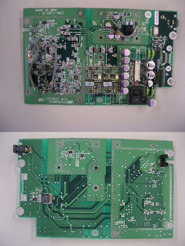
Click to zoom
Application Details
- Equipment Class
- UWB - Ultra Wideband Transmitter
- Date of Grant
- Dec 20, 2007
- Application Purpose
- Original Equipment
- Date of Application
- Oct 16, 2007
- Equipment Note
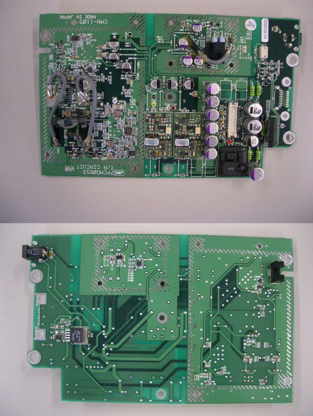
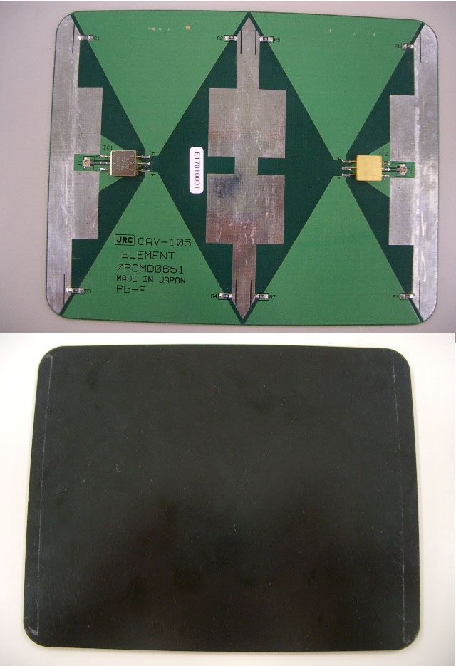
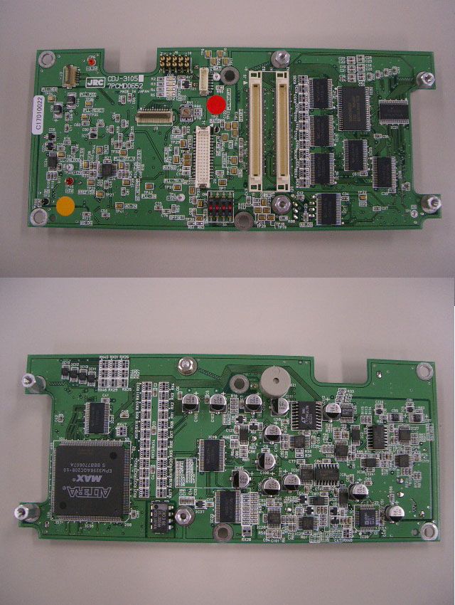
- Ground penetrating radar
- Frequency Range
- 895.00000000 - 1249.00000000
- Company
- Japan Radio Co., Ltd.
- Country
- United States
Documents & Files
Document Text
Text extracted from the exhibit documents filed with the FCC. Open a document above to read the original.
Users Manual
Handy Search Instruction Manual Preface Thank you very much for purchasing this JRC NJJ-95B Handy Search The NJJ-95B RC radar nondestructively locates, detects, and displays the depths and positions of reinforcing steel bars in reinforced concrete structures. Before attempting to operate the NJJ-95B, please read through this instruction manual carefully to learn all of its features and ensure correct and trouble-free operation. Keep the instruction manual handy for reference. Refer to the manual for information about the NJJ-95B or when experiencing trouble during operation. DC01-NJJ-95B First edition September 2006 Before Operation Pictorial Indication Various icons are included in this manual and are shown on these equipment so that you can operate them safely and correctly and prevent any danger to you and/or to other persons and any damage to your property during operation. Such indications and their meanings are as follows. Please understand them before you read this manual. WARNING This indication is shown where any person is supposed to be in danger of being killed or seriously injured if this indication is neglected and this equipment is not operated correctly. CAUTION This indication is shown where any person is supposed to be injured or any property damage is supposed to occur if this indication is neglected and this equipment is not operated correctly. Examples of Pictorial Indication Electric shock The mark indicates CAUTION (including DANGER and WARNING). Detailed content of the specific CAUTION (“Electric Shock” in the example on the left.) is shown in the mark. Disassembling Prohibited Prohibition The mark indicates prohibition. Detailed content of the prohibited action (“Disassembling Prohibited” in the example on the left.) is shown in the mark. Disconnect the power plug Instruction The z mark indicates instruction. Detailed content of the instruction (“Disconnect the power plug” in the example on the left.) is shown in the mark. JRC assumes no liability for any damage (such as damage caused to reinforcing steel bars, electrical pipes, gas pipes, etc.) arising from search results using this radar. FCC NOTICES: This device complies with part 15 of the FCC Rules: Operation is subject to the following conditions: 1. This device many not cause harmful interference, and 2. This device must accept any interference received, Including interference that may cause undesired operation Warning: Changes or modifications to this unit not expressly approved by the party responsible for compliance could void the user’s authority to operate the equipment. Operation of this device is restricted to law enforcement, fire and rescue officials,scientific research institutes, commercial mining companies, and construction companies. Operation by any other party is a violation of 47 U.S.C. § 301 and could subject the operator to serious legal penalties. Coordination Requirements. (a) UWB imaging systems require coordination through the FCC before the equipment may be used. The operator shall comply with any constraints on equipment usage resulting from this coordination. (b) The users of UWB imaging devices shall supply detailed operational areas to the FCC Office of Engineering and Technology who shall coordinate this information with the Federal Government through the National Telecommunications and Information Administration. The information provided by the UWB operator shall include the name, address and other pertinent contact information of the user, the desired geographical area of operation, and the FCC ID number and other nomenclature of the UWB device. This material shall be submitted to the following address: Frequency Coordination Branch., OET Federal Communications Commission 445 12th Street, SW Washington, D.C. 20554 ATTN: UWB Coordination (d) Users of authorized, coordinated UWB systems may transfer them to other qualified users and to different locations upon coordination of change of ownership or location to the FCC and coordination with existing authorized operations. (e) The NTIA/FCC coordination report shall include any needed constraints that apply to day-to-day operations. Such constraints could specify prohibited areas of operations or areas located near authorized radio stations for which additional coordination is required before operation of the UWB equipment. If additional local coordination is required, a local coordination contact will be provided. (f) The coordination of routine UWB operations shall not take longer than 15 business days from the receipt of the coordination request by NTIA. Special temporary operations may be handled with an expedited turn-around time when circumstances warrant. The operation of UWB systems in emergency situations involving the safety of life or property may occur without coordination provided a notification procedure, similar to that contained in CFR47 Section 2.405(a)-(e), is followed by the UWB equipment user. NOTICE: Use of this device as a wall imaging system is prohibited by FCC regulations. <Precautions for Use> WARNING Do not use any battery pack other than the BP-3007-A1 or any AC adapter other than the PW-3009-W. Doing so may cause fire, electric shock, or breakdown. Do not short-circuit the terminals of the battery charger or battery pack. Doing so may cause fire, explosion, or breakdown. Do not insert metallic or flammable objects into the compact flash memory card slot. Doing so may cause injury, fire, electric shock, or breakdown. Do not disassemble, modify, heat, or place battery pack in fire. Doing so may cause fire, explosion, or breakdown. Do not use any charger other than the specified battery charger to charge the battery pack. Doing so may cause fire, electric shock, or breakdown. Do not attempt to disassemble, modify, or attempt to repair the NJJ-95B by yourself. Doing so may cause fire, electric shock, or breakdown. If the power cord is damaged (exposure of the core wire, open circuit failure, or break in the …
Text truncated - open the document above for the full version.
Test Report
Report number: Z071C-07311 Page 2 of 17 ZACTA Technology Corp. FCC ID: CKEHANDYSEARCH FCC Verification Rev. 5.0 Table of contents Page 1. Summary of Test .............................................................................................................................................................3 1.1 Purpose of test..........................................................................................................................................................3 1.2 Standards..................................................................................................................................................................3 1.3 Emission measurement ...........................................................................................................................................3 1.4 Deviation from the standard....................................................................................................................................3 1.5 Modification to the EUT by laboratory ..................................................................................................................3 2. Equipment Under Test ...................................................................................................................................................4 2.1 EUT information .....................................................................................................................................................4 2.2 Operating mode .......................................................................................................................................................4 3. Configuration of equipment...........................................................................................................................................5 3.1 Peripheral(s) used ....................................................................................................................................................5 3.2 Cable(s) used ...........................................................................................................................................................5 3.3 System configuration...............................................................................................................................................5 4. Measurement procedure ................................................................................................................................................6 4.1 Measurement procedure..........................................................................................................................................6 4.2 Test equipment.........................................................................................................................................................7 4.3 Sample of field strength calculation .......................................................................................................................7 5. Measurement result........................................................................................................................................................8 5.1 [§15.509(a)] Operational restrictions......................................................................................................................8 5.2 [§15.509(d), 15.209] Radiated Emission................................................................................................................8 5.3 [§15.509(e)] Radiated Emission .............................................................................................................................9 5.4 [§15.509(f)] Highest radiated emission (fM) .........................................................................................................9 6. Uncertainty of measurement .......................................................................................................................................10 7. Laboratory description ................................................................................................................................................10 8. Configuration photographs ......................................................................................................................................... 11 Radiated emission........................................................................................................................................................ 11 Report number: Z071C-07311 Page 3 of 17 ZACTA Technology Corp. FCC ID: CKEHANDYSEARCH FCC Verification Rev. 5.0 1. Summary of Test 1.1 Purpose of test It is the original test in order to verify conformance to standards listed in section 1.2. 1.2 Standards CFR47 FCC Part 15 Subpart F 1.3 Emission measurement Test Description FCC Rules Section Te s t m e t h o d Te s t UWB bandwidth <960MHz GPR operated by law enforcement, etc. Eligible for licensing (Part 90) Cease operation 10 seconds after release 15.509 (a)-(c) FCC 02-48 Applied Quasi-peak emissions 15.209 15.509(d) FCC 02-48 ANSI C63.4-2003 Applied RMS emissions >960MHz 15.509(d) FCC 02-48 Applied RMS emissions in GPS bands 15.509(e) FCC 02-48 Applied Emission at frequency of highest emission 15.509(f) FCC 02-48 Applied Conducted emission 15.207 FCC 02-48 Not applied *1 Note 1: Test was not applied because the EUT is powered by batteries. 1.4 Deviation from the standard None 1.5 Modification to the EUT by laboratory None Report number: Z071C-07311 Page 4 of 17 ZACTA Technology Corp. FCC ID: CKEHANDYSEARCH FCC Verification Rev. 5.0 2. Equipment Under Test 2.1 EUT information No. EUT Company Model No.Serial No.FCC ID Comment 1 HANDY SEARCH Japan Radio Co., Ltd.NJJ-95B 09 CKEHANDYSEARCH- 2.2 Operating mode Imaging mode The EUT was operated at a pulse repetition rate (PRR) of 50kHz. The Start switch was configured to turn the transmitter on continuously. Note that the EUT can operate with an external print…
Text truncated - open the document above for the full version.
Contact Information
Applicant
Yuji Kinoshita(General Manager)
Technical Contact
Zacta Technology CorporationRie Aita
[email protected]+81-238-28-2881
5-4149-7 Hachimanpara · Yonezawa · Japan
Non-Technical Contact
Zacta Technology CorporationRie Aita
[email protected]+81-238-28-2881
Test Firm
TUV SUD Zacta Ltd.Jun Shimanuki
Technical Specifications
| # | Rule Parts | Frequency Range | Power Output |
|---|---|---|---|
| 1 | 15F | 895 MHz - 1.25 GHz | - |
Other Applications from Japan Radio Co., Ltd.

CKENTG1014
May 09, 20235G Radio Unit
Equipment Class
CBD - Citizens Band Category A and B Devices
CKENKE2632
Oct 21, 2015Solid State S-Band Marine Radar
Equipment Class
MRD - Marine Radar
CKENJJ-200
Jan 22, 2015Handy Search
Equipment Class
UWB - Ultra Wideband Transmitter
CKEJRN-130K
Oct 21, 20143G/GSM IT Controller
Equipment Class
PCB - PCS Licensed Transmitter
CKENKE1066
Feb 04, 2014MARINE RADAR
Equipment Class
MRD - Marine Radar