CKENCR-333Marine NAVTEX Receiver
Japan Radio Co., Ltd.
Click to zoom
Application Details
- Equipment Class
- RNV - Part 80 NAVTEX Receiver
- Date of Grant
- Sep 15, 2005
- Application Purpose
- Original Equipment
- Date of Application
- Aug 15, 2005
- Equipment Note
- Marine NAVTEX Receiver
- Frequency Range
- 0.51800000 - 4.20900000
- Company
- Japan Radio Co., Ltd.
- Country
- United States
Documents & Files
Document Text
Text extracted from the exhibit documents filed with the FCC. Open a document above to read the original.
Users Manual
NAVTEX Receiver NCR-333 Instruction Manual 7ZPJD0304 i Preface Thank you for purchasing NCR-333 NAVTEX Receiver. The NAVTEX receiver automatically receives NAVTEX service broadcasts supplied in English and other optional languages. • Be sure to read this manual for full comprehension before using the equipment. • Save this manual near at hand for quick reference in the future. Make use of this manual when experiencing operation difficulties. ii WARNING Before Operation Concerning the symbols This manual uses the following symbols to explain correct operation and to prevent injury or damage to property. The symbols and descriptions are as follows. Understand them before proceeding with this manual. Indicates a warning that, if ignored, may result in serious injury or even death. Indicates a caution that, if ignored, may result in injury or damage to property. Examples of symbols The △ symbol indicates caution (including DANGER and WARNING). The illustration inside the △ symbol specifies the content of the caution more accurately. (This example warns of possible electrical shock.) The symbol indicates that performing an action is prohibited. The illustration inside the symbol specifies the contents of the prohibited operation. (In this example disassembly is prohibited.) The ● symbol indicates operations that must be performed. The illustration inside the ● symbol specifies obligatory instructions. (In this example unplugging is the obligatory instruction.) CAUTION iii WARNING Handling Precautions Do not disassemble or customize this unit. Doing so may cause fire, electrical shock or malfunction. Do not get this equipment wet or spill any liquids on or near this equipment. Doing so causes electrical shock or malfunction. Do not use a voltage other than specified. Doing so may cause fire, electrical shock or malfunction. Do not attempt to inspect or repair the inside of this equipment with the exception of qualified service personnel, as doing so may cause fire, electric shock or malfunction. If any malfunctions are detected, contact our service center or agents. iv CAUTION Handling Precautions Do not use this equipment for anything other than specified. Doing so may cause malfunction or damage to persons. Do not adjust the trimmer resistors or the trimmer capacitors on the PCB unit. Doing so may cause malfunction or damage to persons. They are preset at the factory. Do not install this equipment in a place other than specified or in one with excessive humidity, steam, dust or soot. Doing so may cause fire, electric shock, malfunction or damage to persons. Do not place this equipment anywhere vibration or impact is likely to occur. Doing so may cause a fall or damage to property and persons. Do not place any objects on this equipment. Doing so may cause a fall, malfunction or damage to property and persons. Leave installation of this equipment to our service center or agents. Installation by an unauthorized person may lead to malfunction. v External Views NCR-333 NAVTEX Receiver NAW-333 NAVTEX Antenna vi NBG-319 Power Supply Unit NBG-320 Power Supply Unit vii CONTENTS Preface .................................................................................................................. i Before Operation .................................................................................................. ii Handling Precautions ........................................................................................... iii External Views ...................................................................................................... v 1. GENERAL ..................................................................................................... 1-1 1.1 Outlines .................................................................................................... 1-1 1.2 Features ................................................................................................... 1-1 1.3 Components ............................................................................................. 1-2 1.3.1 Standard Components .......................................................................... 1-2 1.3.2 Options ................................................................................................. 1-2 1.3.3 Configuration ......................................................................................... 1-3 1.4 Outline ..................................................................................................... 1-4 2. INSTALLATION DIAGRAM ............................................................................ 2-1 3. PART NAMES AND FUNCTIONS ................................................................. 3-1 3.1 NCR-333 NAVTEX Receiver .................................................................... 3-1 4. DISPLAYS ..................................................................................................... 4-1 4.1 Displays ................................................................................................... 4-1 4.1.1 Message text screen ............................................................................. 4-1 4.1.2 Message list 1 screen ........................................................................... 4-2 4.1.3 Message list 2 screen ........................................................................... 4-2 4.1.4 Save message list screen ..................................................................... 4-3 4.1.5 Position/date screen ............................................................................. 4-3 4.1.6 Setup screen ......................................................................................... 4-4 5. INSTALLATION ............................................................................................. 5-1 5.1 Installation ................................................................................................ 5-1 5.1.1 Selection of location .............................…
Text truncated - open the document above for the full version.
Attestation Statements
JAPAN RADIO CO., LTD. 1021 SW KLICKITAT WAY BLDG. D, SUITE 101 SEATTLE, WA 98134 PHONE: (206) 654-5644/FAX: (206) 654-70307 Date: August 16, 2005 STATEMENT TO THE FCC The applicant, Japan Radio Company, Ltd., confirms that the MARINE NAVTEX RECEIVER ,FCC ID: CKENCR-333meets the requirements of: 1. IMO Resolution MSC 148 (77) 2. IMO Resolution A525 (13) 3. IEC 61097 4. IEC 60945 With Best Regards, Japan Radio Company, Ltd. Per: Eric D’Ancicco High Seas Service Coordinator [email protected] 206-654-5644 XT 1100
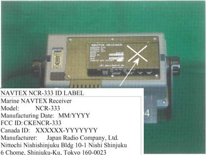
ID Label/Location Info
NAVTEX NCR-333 ID LABEL Marine NAVTEX Receiver Model: NCR-333 Manufacturing Date: MM/YYYY FCC ID: CKENCR-333 Canada ID: XXXXXX-YYYYYYY Manufacturer: Japan Radio Company, Ltd. Nittochi Nishishinjuku Bldg 10-1 Nishi Shinjuku 6 Chome, Shinjuku-Ku, Tokyo 160-0023
Operational Description
1-1 1. GENERAL 1.1 Outlines The NAVTEX NCR-333 function receives and displays the various types of information broadcast at frequencies of 518 kHz, 490 kHz and 4209.5 kHz, such as: navigational warning, meteorological warning, search and rescue information, and other types of information. NCR-333 also provides the function that selects information type and coast station for intended uses. 1.2 Features ● Receiving NAVTEX broadcasts ━━━━━━━━━━━━━━━━━━━━━━━━━━━━━━━━━━━━━━━━━━━ NCR-333 receives NAVTEX broadcasts automatically on 518 kHz, 490 kHz, and 4209.5 kHz. ● Large screen allows comfortable visibility ━━━━━━━━━━━━━━━━━━━━━━━━━━━━━━━━━━━━━━━━━━━ NCR-333 has a 5.7-inch LCD screen display with clear visibility. It also provides three different character sizes of display, and can be selected at your convenience. ● Message saving function ━━━━━━━━━━━━━━━━━━━━━━━━━━━━━━━━━━━━━━━━━━━ NCR-333 can store up to 200 message identification codes for 70 hours. Moreover, the stored message of each channel can be saved up to 50 messages permanently. ● Automatically receiving station setting function ━━━━━━━━━━━━━━━━━━━━━━━━━━━━━━━━━━━━━━━━━━━ NCR-333 can select receiving stations automatically on GPS position data is valid. ● Permanent storage of data settings ━━━━━━━━━━━━━━━━━━━━━━━━━━━━━━━━━━━━━━━━━━━ NCR-333 can set and store the message type and seashore station that receive to internal memory. The data, therefore, does not need to be re-set, even after power has been turned off. ● Dual voltage supply input ━━━━━━━━━━━━━━━━━━━━━━━━━━━━━━━━━━━━━━━━━━━ NCR-333 can be used on wither 24 V DC or 12 V DC vessels. ● Self-diagnosis Function ━━━━━━━━━━━━━━━━━━━━━━━━━━━━━━━━━━━━━━━━━━━ NCR-333 has automatic self-diagnosis function. This function allows easy maintenance and high system reliability. ● Connection to external equipment ━━━━━━━━━━━━━━━━━━━━━━━━━━━━━━━━━━━━━━━━━━━ NCR-333 can be used with the JRC Total Navigator (ECDIS) and external serial printers.
Parts List/Tune Up Info
7-3 7. 3 Trouble Shootings 7.3.1 Trouble Shootings For reference, this section presents a troubleshooting guideline for finding defective sections. Symptom of Error Possible Cause or Cause of FaultCountermeasures Power is not distributed from the inboard distribution panel. Supply power from the distribution panel. Power is not supplied from the power supply unit or NCR-333. Check that the wiring of the power unit is correct. Check that the output voltage of the power unit or NCR-333 is correct. Power that the power unit supplies is out of range. Replace the power unit. The fuses in the Power Supply Unit (Option) are blown out. Check that the wiring is correct and replace the fuses. The power supply cable is broken. Replace the power supply cable. Power is not supplied when the power switch is pressed. The controller switch is broken. Replace the CMD-953 circuit board. The LCD malfunctions. Replace the LCD. Some dots are missing on the LCD. The control unit malfunctions. Replace the CMJ-501N circuit board. The buzzer malfunctions. Replace the CMD-953 circuit board.No alarming sound is generated. The control unit malfunctions. Replace the CMJ-501N circuit board. The control unit malfunctions. Replace the CMJ-501N circuit board. The illumination does not light. The LCD malfunctions. Replace the LCD. The polarity or antenna cable is incorrect. Check if the polarity is correct and connect it. Neither the receiving station nor the message type is selected correctly. Refer to “6.3.1” or “6.3.2”. The NAVTEX antenna (NAW-333) is damaged. Replace the NAW-333. No NAVTEX message is received. The following alarm number appears: 002, 003, or 004. Internal receiver 1, 2 or 3 is broken. Replace the CMN-2333. The polarity of the serial cable is incorrect. Check if the polarity is correct and connect it. The interface between the sensor and NCR-333 is incorrect. Check if the interface is correct before its connection. The sentence that the sensor generates is not supported by the NCR-333. Check the output command and the version. The serial format (baud rate, etc.) does not meet the setting of the controller. Check the serial format of the sensor. The sensor (GPS, gyro, rate-of-turn indicator) malfunctions. Replace the sensor. Sensor data (external GPS, gyro, and rate-of-turn) cannot be loaded. Do not attempt to inspect or repair the inside of this equipment with the exception of qualified service personnel, as doing so may cause fire, electric shock or malfunction. If any malfunctions are detected, contact our service center or agents. WARNING 7-4 Symptom of Error Possible Cause or Cause of FaultCountermeasures Sensor data (external GPS, gyro, and rate-of-turn) cannot be loaded. The DPU (CMJ-501N) malfunctions. Replace the CMJ-501N circuit board. The external printer is not ON. Turn on the external printer. The printer power is not turned on. Check the printer power cable. The external printer does not print Printer property (printer settings) is incorrect. Refer to “6.3.4.5”. 7.3.2 Maintenance Units Maintenance units for repair are followings. No. Unit Name Model Note 1 RX UNIT CMN-2333 2 DPU CMJ-501N 3 KEYBOARD UNIT CMD-953 4 NAVTEX ANTENNA NAW-333-1 ANTENNA for NCR-333 5 POWER SUPPLY UNIT NBG-319 DC: +12/24Vdc 6 POWER SUPPLY UNIT NBG-320 AC: 110/220Vac, DC: +12/24Vdc 7 Whip Antenna 5ABBE00001 0.6 m Fuses No. Unit Name Model Note 1 5A Fuse ULTSC 5A N1 For NBG-319 2 2A Fuse MQ4 250V 2A For NBG-320 3 4A Fuse MQ2 125V 4A For NBG-320 7.3.3 Spear parts for periodic maintenance Spear parts for periodic maintenance are followings. No. Unit Name Code Decline period Note 1 LCD Unit CCN-392 40,000 hours 5 years in continuous operation 2 Printer (Option) DPU-414 Approx. 500,000 lines When the thermal paper of 25m roll length is used, about 90 thermal papers can be used.
Test Report
REPORT ON Limited Type Approval Testing of the Japan Radio Company Limited NCR-333 Navtex Receiver, NAW-333 Navtex Antenna and NBG-319, NBG-320 Power Supplies in accordance with IEC 60945 (August 2002) and IEC 61097-6 Ed.2 (February 2005) COMMERCIAL- IN-CONFIDENCE Report Number RM614104/01 Issue 1 June 2005 Competence. Certainty. Quality. TUV Product Service Ltd, Octagon House, Concorde Way, Segensworth North, Fareham, Hampshire, United Kingdom, PO15 5RL Tel: +44 (0) 1489 558100. Website: www.tuvps.co.uk ; www.babt.com Report Number RM614104/01 Issue 1 PAGE 1 of 94 COMMERCIAL-IN-CONFIDENCE REPORT ON Limited Type Approval Testing of the Japan Radio Company Limited NCR-333 Navtex Receiver, NAW-333 Navtex Antenna and NBG-319, NBG-320 Power Supplies in accordance with IEC 60945 (August 2002) and IEC 61097-6 Ed.2 (February 2005). Report Number RM614104/01 Issue 1 June 2005 PREPARED FOR Japan Radio Company Limited 1-1, Shimorenjaku 5-chome Mitaka Tokyo 181-8510 Japan PREPARED BY R A Blagg Principal Engineer APPROVED BY M J Hardy UKAS Signatory DATED 24 th June 2005 DISTRIBUTION Japan Radio Company, Mitaka, Tokyo Copy No. 1 Mr. James Moon, JRC, Amsterdam Copy No. 2 Mr. Peter Goddard, QinetiQ Copy No. 3 BABT Copy No. 4 COMMERCIAL-IN-CONFIDENCE Report Number RM614104/01 Issue 1 PAGE 2 of 94 COMMERCIAL-IN-CONFIDENCE CONTENTS Section Page No 1 REPORT SUMMARY 1.1 Status ..........................................................................................................................................5 1.2 Test House Declaration .............................................................................................................6 1.3 Brief Summary of Results .........................................................................................................7 1.4 Application Form ......................................................................................................................10 1.5 Additional Information..............................................................................................................18 2 TEST DETAILS The list of measurements performed from IEC 60945: Clause 7.2 Excessive Conditions ......................................................................................20 Clause 8.2.1 Dry Heat Storage.............................................................................................25 Clause 8.2.2 Dry Heat ...........................................................................................................26 Clause 8.3 Damp Heat.......................................................................................................32 Clause 8.4 Low Temperature ............................................................................................38 Clause 8.7 Vibration ...........................................................................................................44 Clause 8.8 Rain ..................................................................................................................45 Clause 11.1 Acoustic Noise and Signals ............................................................................46 The list of measurements performed from IEC 61097-6 Ed.2: Clause 8.1 INS Input Electrical Tests ................................................................................47 Clause 8.2 INS Input Performance Tests..........................................................................48 Clause 8.3 INS Output Electrical Tests .............................................................................49 Clause 8.4 INS Output Performance Tests.......................................................................50 Clause 8.5 Printer Output Electrical Tests ........................................................................51 Clause 8.6 Printer Output Performance Tests ..................................................................52 Clause 9.1 Exclusion of Stations .......................................................................................53 Clause 9.2 Exclusion of Message Categories ..................................................................54 Clause 9.3 Receiver Test Facility ......................................................................................55 Clause 9.4 Search and Rescue (SAR) Alarm Provision and Reset ................................56 Clause 9.5 Additional Alarms.............................................................................................57 Clause 10.1 Call Sensitivity..................................................................................................58 Clause 10.2 Interference Rejection and Blocking Immunity...............................................59 Clause 10.3 Co-channel Rejection ......................................................................................60 COMMERCIAL-IN-CONFIDENCE Report Number RM614104/01 Issue 1 PAGE 3 of 94 COMMERCIAL-IN-CONFIDENCE CONTENTS Section Page No 2 The list of measurements performed from IEC 61097-6 Ed.2: Clause 10.4 Intermodulation ................................................................................................61 Clause 10.5 Off Frequency Transmitter ..............................................................................62 Clause 10.6 Simultaneous Operation on Several Receive Frequencies..........................63 Clause 10.7 Protection of Input Circuits ..............................................................................64 Clause 12.1 Internal Storage, Tagging and Erasure of Messages ....................................65 Clause 12.2 Erasure of Message Identifications/Storage Time .........................................66 Clause 12.4 Reception of Messages with Character Errors ..............................................67 Clause 12.5 Unsatisfactory Reception ................................................................................68 Clause 12.6 Power Off Check ........................................................…
Text truncated - open the document above for the full version.
Contact Information
Applicant
Yuji Kinoshita(General Manager)
Technical Contact
Japan Radio Co., Ltd.Eric K D'Ancicco
[email protected]206-654-5644
1021 S.W. Klickitat Way · Seattle, Washington · United States
Non-Technical Contact
Japan Radio Co., Ltd.Toshinori Amemiya
[email protected]206-654-5644
Technical Specifications
| # | Rule Parts | Frequency Range | Power Output |
|---|---|---|---|
| 1 | 80.1101(c)(1) | 0.518 MHz - 4.209 MHz | - |
Other Applications from Japan Radio Co., Ltd.

CKENTG1014
May 09, 20235G Radio Unit
Equipment Class
CBD - Citizens Band Category A and B Devices
CKENKE2632
Oct 21, 2015Solid State S-Band Marine Radar
Equipment Class
MRD - Marine Radar
CKENJJ-200
Jan 22, 2015Handy Search
Equipment Class
UWB - Ultra Wideband Transmitter
CKEJRN-130K
Oct 21, 20143G/GSM IT Controller
Equipment Class
PCB - PCS Licensed Transmitter
CKENKE1066
Feb 04, 2014MARINE RADAR
Equipment Class
MRD - Marine Radar