CKENKE1532MARINE RADAR
Japan Radio Co., Ltd.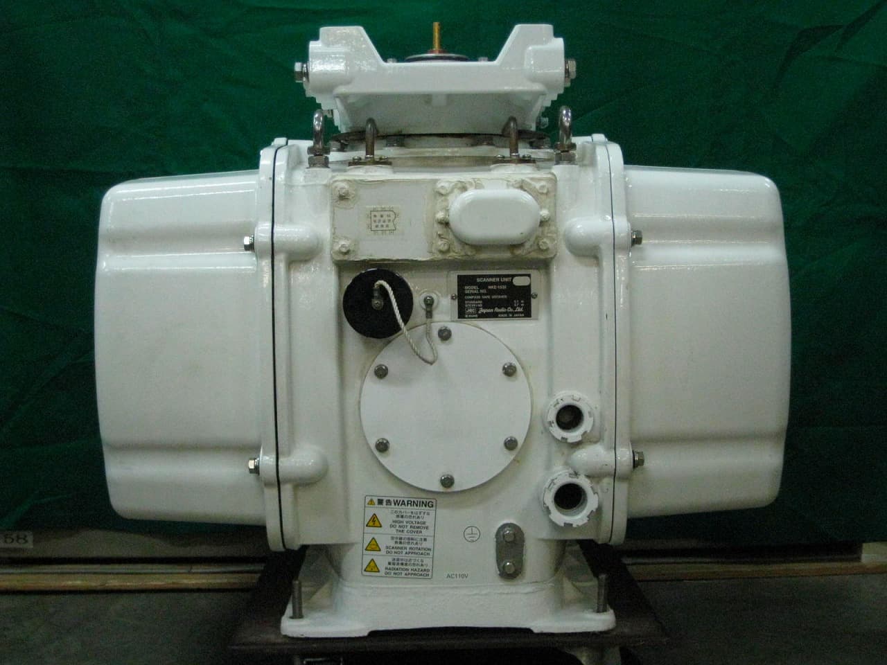
Click to zoom
Application Details
- Equipment Class
- MRD - Marine Radar
- Date of Grant
- Jan 12, 2011
- Application Purpose
- Original Equipment
- Date of Application
- Jan 12, 2011
- Equipment Note
- MARINE RADAR
- Frequency Range
- 2900.00000000 - 3100.00000000
- Company
- Japan Radio Co., Ltd.
- Country
- United States
Documents & Files
Document Text
Text extracted from the exhibit documents filed with the FCC. Open a document above to read the original.
Users Manual
MARINE RADARMARINE RADAR EQUIPMENTEQUIPMENT INSTRUCTIONINSTRUCTION MANUALMANUAL JMA-9172-SAJMA-9172-SA 01ETM ISO 9001, ISO 14001 Certified Printed in Japan Marine Service Department [email protected] Telephone :Facsimile :e-mail : AMSTERDAM Branch Telephone :Facsimile :e-mail : [email protected] SEATTLE Branch Telephone :Facsimile :e-mail : [email protected] CODE No.7ZPRD0730 CODE No.7ZPRD0730 DEC. 2009 Edition 2 JRCDEC. 2009 Edition 2 JRC Not use the asbestos For further information,contact: URL http://www.jrc.co.jp i ◆◆◆PRECAUTIONS BEFORE OPERATION◆◆◆ ■Cautions for high voltage High voltages from hundreds volts to tens of thousands volts are to be applied to the electronic equipment such radio and radar devices. You do not face any danger during normal operation, but sufficient cares are required for maintenance, inspection and adjustment of their internal components. (Maintenance, check-up and adjustment of the inside of the equipment are prohibited except by maintenance specialists.) High voltages of tens of thousands volts are so dangerous as to bring an instantaneous death from electric shock, but even voltages of hundred volts may sometimes lead to a death from electric shock. To prevent such an accident, make it a rule to turn off the power switch, discharge capacitors with a wire surely earthed on an end make sure that internal parts are no longer charged before you touch any parts inside these devices. At the time, wearing dry cotton gloves ensures you further to prevent such danger. It is also a necessary caution to put one of your hands in the pocket and not to use your both hands at the same time. It is also important to select a stable foothold always to prevent additional injuries once you were shocked by electricity. If you were injured from electric shock, disinfect the burn sufficiently and get it taken care of promptly. ■What to do in case of electric shock When finding a victim of electric shock, turn off the power source and earth the circuit immediately. If it is impossible to turn off the circuit, move the victim away promptly using insulators such as dry wood plate and cloth without touching the victim directly. In case of electric shock, breathing may stop suddenly if current flows to the respiration center in the brain. If the shock is not so strong, artificial respiration may recover breathing. When shocked by electricity, the victim will come to look very bad with weak pulse or without beating, resulting in unconsciousness and rigidity. In this case, it is necessary to perform an emergency measure immediately. ii ◆◆◆FIRST-AID TREATMENTS◆◆◆ ☆First-aid treatments As far as the victim of electric shock is not in dangerous condition, do not move him and practice artificial respiration on him immediately. Once started, it should be continued rhythmically. (1)Do not touch the victim confusedly as a result of the accident, but the rescuer may also get an electric shock. (2)Turn off the power source calmly and move the victim away quietly from the electric line. (3)Call a physician or ambulance immediately or ask someone to call a doctor. (4)Lay the victim on this back and loosen his necktie, clothes, belt, etc. (5) a.Examine the victim's pulse. b.Examine his heartbeat bringing your ear close to his heart. c.Examine his breathing bringing the back of your hand or your face close to his face. d.Check the size of the pupils of his eyes. (6)Open the victim's mouth and take out artificial teeth, cigarette or chewing gum if any. Keep his mouth open, stretch his tongue and insert a towel or the like in his mouth to prevent the tongue from suffocating. (If it is hard to open his mouth due to set teeth, open it with a screwdriver and insert a towel in this mouth.) (7)Then, wipe his mouth so that foaming mucus does not accumulate inside. iii ☆When pulse is beating but breathing has stopped (Mouth-to-mouth respiration) Fig 1. (1)Tilt the victim's head back as far as this face looks back. (A pillow may be inserted his neck.) (2)Push his jaw upward to open his throat wide (to spread his airway). (3)Pinch the victim's nostrils and take a deep breath, block his mouth completely with yours and blow into his mouth strongly. Take a deep breath again and blow into his mouth. Continue this 10 to 15 times a minutes (blocking his nostrils). (4)Carefully watch that he has recovered his natural breathing and atop practicing artificial respiration. (5)If it is difficult to open the victim's mouth, insert a rubber or vinyl tube into one of his nostrils and blow into it blocking the other nostril and his mouth completely. (6)When the victim recovers consciousness, he may try to stand up suddenly, but let him lie calmly and serve him with a cup of hot coffee or tea and keep him warm and quiet. (Never give him alcoholic drinks.) Method of mouth-to-mouth respiration by raising hea Fig 1. Mouth-to mouth respiration (1)Raise the victim's head. Support his forehead with one of your hand and his neck with the other hand. When you tilt his head backward, the victim, in most cases, opens his mouth to the air. This makes mouth- to mouth respiration easy. (2)Cover his mouth as widely as possible with yours and press your cheek against his nose or, pinch his nostrils with your fingers to prevent air from leaking. (3)Blow into his lungs. Continue blowing into his mouth until his breast swells. Blow into his mouth as quickly as possible for the first 10 times. 1 2 3 iv ☆When both pulse and breathing have stopped Perform the (Cardiac massage) Fig 2. and (Mouth-to-mouth respiration) Fig 1. When no pulse has come not to be felt, his pupils are open and no heartbeat is heard, cardiac arrest is supposed to have occurred and artificial respiration must be performed. (1)Place your both hands, one hand on the other, on the lower one third area of his breastbone and compress his breast with your elbows applying your weight on…
Text truncated - open the document above for the full version.
Users Manual
5-34 JMA-9172-SA Instruction Manual > 5.OPERATION OF TARGET TRACKING AND AIS > 5.3 AIS OPERATION 4)Set an ending bearing and range by turning the [EBL] dial and [VRM] dial, and left-click. 5.3.7.4AIS Filter Display On/Off (Filter Display) Procedures 1)Open the AIS Filter Setting menu by performing the following menu operation. → 2)Left-click the item button of . Filter Display will be set to on or off. 5.3.7.5Display of Targets outside AIS Filter (Filter Mode) Procedures 1)Open the Filter Mode menu by performing the following menu operation. → 2)Left-click the item button of . i When the automatic activation function is enabled, the filter range is automatically changed for covering the automatic activation zone. Thus, the automatic activation zone is always within the filter range. : Displays only AIS targets in the AIS filter. : Displays AIS targets in the AIS filter by priority, and also displays targets outside the AIS filter. i Activated AIS targets can be displayed even when they are outside the AIS filter. AIS 4. AIS Filter Setting 3. Filter Display AIS 4. AIS Filter Setting 6. Filter Mode Display Priority JMA-9172-SA Instruction Manual > 5.OPERATION OF TARGET TRACKING AND AIS > 5.3 AIS OPERATION 5-35 5 5.3.7.6Point Filter AIS targets which are not displayed because they are outside the AIS filter or at low priority levels can be activated by giving a higher priority to them. Procedures 1)Put the cursor on the position where a point filter is to be set, and right-click to select the filter to be set. 2)The setting items for cursor modes will be displayed.Left-click . A point filter will be set at the cursor position. If an AIS target is in the point filter, it will be activated. When an AIS target is activated or an AIS target is not found within one minute, the point filter will be cleared. 5.3.8Conditions for Deciding AIS Target to be Lost About a lost target When the data of an AIS target cannot be received for a specified time, the target is decided to be lost and the target data is deleted. As shown in the table below, the time until target data is deleted varies depending on the class of receive data and the target status. If the [ALARM ACK] key is pressed, the symbol is cleared. i The point filter's range is 1 nm, and cannot be changed. Deciding AIS Target to be Lost Target statusTime until data deletion SOLAS ship (Class A)SOLAS ship (Class B) Vessel below 3 knots (Class A) or 2 knots (Class B) and it is now at anchor or on the berth 18 min18 min Vessel of 3 knots or more and it is now at anchor or on the berth 60 sec18 min Vessel of 0 to 14 knots (Class B: 0 to 14 knots) 60 sec180 sec Vessel of 14 to 23 knots 36 sec180 sec Vessel of 23 knots or more 30 sec180 sec SAR (Search and Rescue) 60 sec60 sec ATON (Aid to Navigation) 18 min18 min Base Station 60 sec60 sec i When a dangerous target ship is lost, a lost alarm is issued and the symbol changes to a lost symbol. The lost symbol will display continuously on the last-received position. 2. ACT AIS 5-36 JMA-9172-SA Instruction Manual > 5.OPERATION OF TARGET TRACKING AND AIS > 5.3 AIS OPERATION 5.3.9Setting Conditions for AIS Alarm (AIS Alarm Setting) Conditions for issuing a Lost alarm and CPA/TCPA alarm for AIS targets can be set. 5.3.9.1Setting of Condition for Lost Alarm Procedures 1)Open the AIS Alarm Setting menu by performing the following menu operation. → 2)Left-click the item button of . The setting items for Lost Alarm will be displayed. 3)Left-click the item button corresponding to the condition to be set. 5.3.9.2Setting of Condition for CPA/TCPA Alarm Procedures 1)Open the AIS Alarm Setting menu by performing the following menu operation. → 2)Left-click the item button of . The setting items for CPA/TCPA Alarm is switched. : A lost alarm is not issued. i i. A lost alarm is not issued for sleeping AIS targets. : A lost alarm is issued only for AIS targets for which a dangerous target alarm has been issued. : A lost alarm is issued only for activated AIS targets and AIS targets for which a dangerous target alarm has been issued. : A lost alarm is issued only for activated AIS targets, data indicated AIS targets and AIS targets for which a dangerous target alarm has been issued. : A CPA/TCPA alarm is not issued. i i. When the Lost Alarm menu set to Off, the CPA ring color changes to dark color. : A CPA/TCPA alarm is issued only for activated AIS targets. : A CPA/TCPA alarm is issued for all AIS targets on the radar display. AIS 6. AIS Alarm Setting 1. Lost Alarm Off Danger ACT &Danger ACT&Danger&Select AIS 6. AIS Alarm Setting CPA/TCPA Alarm Off ACT ACT &Sleep JMA-9172-SA Instruction Manual > 5.OPERATION OF TARGET TRACKING AND AIS > 5.4 DECISION OF TARGETS AS IDENTICAL (Association) 5-37 5 5.4DECISION OF TARGETS AS IDENTICAL (Association) 5.4.1Setting of Function to Decide Targets as Identical (Association) When an AIS target and a tracking target are decided to be identical, an association symbol is displayed for the targets regarded as identical. In this case, the AIS target symbol is automatically activated. Procedures 1)Left-click the in Target Information located at the upper right of the display. Association will be set to on or off. 5.4.2Setting of Conditions for Deciding AIS and Tracked Targets as Identical (Association Setting) Procedures 1)Open the Association Setting menu by performing the following menu operation. → The Association Setting menu will appear. 2)Select and enter the item to be set. Conditions for deciding targets as identical will be set. When the differences of all item between AIS and tracked target are under the set conditions.. • Turn off in order not to make a decision on if targets are identical, or in order to display symbols that have disappeared. Attention Association Association AIS 1. Association Setting 5-38 JMA-9172-SA Instruction Manual > 5.OPERATION OF TARGET TRACKING AND AIS > 5.4 DECISION OF TARGETS AS IDENTICAL (Association) Once regard as identical, when one of the diffe…
Text truncated - open the document above for the full version.
Test Report
3. TEST RESULTS SUMMARY 3.1 Mechanical Tests Appearance and Structure Scanner Unit Good 3.2 Electrical Tests 3.2.1 Working of each operation unit Scanner Unit Good 3.2.2 Scanner VSWR Frequency (MHz) VSWR 3020 1.10 3050 1.10 3080 1.10 Scanner Rotation Speed 24 rpm 3.2.3 Transmitter Type / Ser. No. CMN-750 / No.4 ○Operating Frequency P0N Q0N SP1 ( 1st : 0.07μs, 2nd : 4.6μs) 3040.2 MHz 3060MHz±4MHz MP1( 1st : 0.14μs, 2nd : 9.1μs) 3040.2 MHz 3060MHz±4MHz MP2( 1st : 0.29μs, 2nd : 9.1μs) 3040.2 MHz 3060MHz±4MHz LP1( 1st : 0.57μs, 2nd : 9.1μs) 3040.2 MHz 3060MHz±4MHz LP2( 1st : 1.14μs, 2nd : 18.3μs) 3040.2 MHz 3060MHz±4MHz ○RF Power Output (Mean Power) P0N Q0N SP1( 1st : 0.07μs, 2nd : 4.6μs) 0.04W 2.4W MP1( 1st : 0.14μs, 2nd : 9.1μs) 0.07W 4.6W MP2( 1st : 0.29μs, 2nd : 9.1μs) 0.16W 4.6W LP1( 1st : 0.57μs, 2nd : 9.1μs) 0.18W 2.6W LP2( 1st : 1.14μs, 2nd : 18.3μs) 0.18W 2.6W ○Pulse Width P0N Q0N SP1( 1st : 0.07μs, 2nd : 4.6μs) 0.07μs 4.5 μs MP1( 1st : 0.14μs, 2nd : 9.1μs) 0.14μs 9.1μs MP2( 1st : 0.29μs, 2nd : 9.1μs) 0.28μs 9.1μs LP1( 1st : 0.57μs, 2nd : 9.1μs) 0.56μs 9.1μs LP2( 1st : 1.14μs, 2nd : 18.3μs) 1.13μs 18.2μs ○Repetition Frequency SP1( 1st : 0.07μs, 2nd : 4.6μs) 1860Hz MP1( 1st : 0.14μs, 2nd : 9.1μs) 1860Hz MP2( 1st : 0.29μs, 2nd : 9.1μs) 1860Hz LP1( 1st : 0.57μs, 2nd : 9.1μs) 1280Hz LP2( 1st : 1.14μs, 2nd : 18.3μs) 640Hz ○Spurious Emission at Antenna Terminal Good ○Field strength of spurious radiation Good ○Radiofrequency radiation exposure limits Good 3.2.4 Receiver IF Center Frequency 63MHz IF Bandwidth 30MHz 3.2.5 Input Voltage and Current (at MP2) DC.48V 1.75A (84W) 3.3 Overall Tests Preheat Time (stand-by to transmission) 6 seconds Input Variation (43.2Vdc‐52.8Vdc) Good Overall Sensitivity Good Minimum Range Good Bearing Accuracy Good Mechanical Noise Good 4.1 RF Power Output 47 CFR sec. 2.1046 4.1.1 TEST SETUP 4.1.2 TEST INSTRUMENTS DESCRIPTION & MANUFACTURER MODEL NO. SERIAL NO. CALIBRATION DATE CALIBLATION DUE DATE 1 Double Ridge Horn Antenna ETS LINDGREN 3117 00091928 NA NA 2 Adaptor MDL MFR-01456 284AC106-E-CPRF 0741 NA NA 3 Direction Coupler (30dB) NIHONKOHSYA WDK-039U30 97105.3 NA NA 4 High Power Dummy Load ATM 2D4-745-7 327905-01 NA NA 5 Coaxial Cable STORM 90-078-10MTR MFP-57500 05-02-201 NA NA 6 Spectrum Analyzer Agilent E4448A MY46180420 Sep. 24. 2010 Sep. 2011 4.1.3 TEST PROCEDURES Reference to Section 2.2.17 Radiated Power Output on TIA-603-C. 4.1.4 EUT OPERATING CONDITIONS a. Placed the EUT on the testing table. b. Prepared other computer systems for controlling EUT and placed them outside of testing area. c. EUT will be transmitted five pulses are 0.07usec/4.6usec/2280Hz, 0.14usec/9.1usec/2280Hz, 0.29usec/9.1usec/2280Hz, 0.57usec/9.1usec/1280Hz and 1.14usec/18.3usec/640Hz. 4.1.5 TEST RESULTS The radiated power output is calculated by the following: iatedaverageraddBmpower i i LOSSLVLi )108/1log(10 8 1 10 ∑ = = + = ○RF Power Output (P0N) Pulse width [usec] PRF [Hz] averageradiated power [dBm] i LVL [dBm] LVL + LOSS [dBm] LVL [dBm] LVL + LOSS [dBm] LVL [dBm] LVL + LOSS [dBm] LVL [dBm] LVL + LOSS [dBm] LVL [dBm] LVL + LOSS [dBm] 1 -27.27 6.52 -22.25 11.54 -16.7617.03 -11.89 21.9 -9.09 24.7 2 -27.28 6.51 -22.25 11.54 -16.7517.04 -11.89 21.9 -9.09 24.7 3 -27.27 6.52 -22.26 11.53 -16.75 17.04 -11.87 21.92 -9.12 24.67 4 -27.27 6.52 -22.26 11.53 -16.75 17.04 -11.87 21.92 -9.12 24.67 5 -27.28 6.51 -22.25 11.54 -16.74 17.05 -11.88 21.91 -9.11 24.68 6 -27.27 6.52 -22.26 11.53 -16.75 17.04 -11.88 21.91 -9.12 24.67 7 -27.27 6.52 -22.26 11.53 -16.75 17.04 -11.88 21.91 -9.12 24.67 8 -27.27 6.52 -22.25 11.54 -16.75 17.04 -11.87 21.92 -9.12 24.67 0.29(P0N)0.14(P0N) 640 1.14(P0N) 24.7 0.57(P0N) 21.9 1280 0.07(P0N) 228022802280 17.011.56.5 ○RF Power Output (Q0N) Pulse width [usec] PRF [Hz] Averageradiated power [dBm] i LVL [dBm] LVL + LOSS [dBm] LVL [dBm] LVL + LOSS [dBm] LVL [dBm] LVL + LOSS [dBm] LVL [dBm] LVL + LOSS [dBm] 1 -11.15 22.64 -10.9 22.89 -10.9 22.88 -10.79 23 2 -11.14 22.65 -10.9 22.89-10.9 22.87 -10.8 22.99 3 -11.14 22.65 -10.9 22.89 -10.9 22.87 -10.82 22.97 4 -11.15 22.64 -10.9 22.89 -10.9 22.88 -10.81 22.98 5 -11.14 22.65 -10.9 22.89 -10.9 22.88 -10.82 22.97 6 -11.14 22.65 -10.88 22.91 -10.9 22.88 -10.82 22.97 7 -11.13 22.66 -10.89 22.90 -10.9 22.87 -10.81 22.98 8 -11.14 22.65 -10.89 22.90-10.9 22.87 -10.8 22.99 22.622.922.923.0 18.3(Q0N) 228022801280640 4.6(Q0N)9.1(Q0N)9.1(Q0N) *Loss:33.79dB *LOSS = 55.80dB 4.1.6 TEST CONDITIONS Tamb = 20°C to 25°C, RHamb = 40% ~ 60% EUT input = 48 VDC 4.1.7 STABILLIZATION EUT energized for 10 minutes minimum. 4.1.8 TEST EQUIPMENT JRC Original – Shielded Room Other equipment – see test set-ups. 4.1.9 DATE 29 th October, 2010 TESTED BY D.Wakamiya 4.2 Spurious emission at antenna terminals 47 CFR sec. 2.1051 4.2.1.1 TEST SETUP for range 10kHz to 3.95GHz 4.2.1.2 TEST INSTRUMENT DESCRIPTION & MANUFACTURER MODEL NO. SERIAL NO. CALIBRATION DATE CALIBLATION DUE DATE 1 Direction Coupler (30dB) SHIMADARIKA 5D102 R8200 NA NA 2 High Power Dummy Load ATM 2D4-745-7 327905-01 NA NA 3 High Power Dummy Load ATM 2D4-745-7 327905-02 NA NA 4 Adaptor MDL MFR-01456 284AC106-E-CPRF 0741 NA NA 5 Variable Attenuator HP 8495B 2814A14581 May. 2010 May. 2011 6 Coaxial Cable HUBER+SUHNER SUCOFLEX 104PA 5784 /4PA NA NA 7 Spectrum Analyzer Agilent E4448A MY46180420 Sep. 24. 2010 Sep. 2011 Measurement Point : Antenna terminal Spectrum Analyzer setting: RBW = 10kHz less than 1GHz, 1MHz above 1GHz VBW = 300kHz less than 1GHz, 3MHz above 1GHz Detector Mode = Positive Peak 4.2.1.3 TEST PROCEDURES a. Setup EUT as 4.2.1. b. Transmitted at most powerful pulse and adjusted attenuator for not exceeding the spectrum analyzer maximum rating. c. Transmitted at five pulses are 0.07usec/4.6usec/2280Hz, 0.14usec/9.1usec/2280Hz, 0.29usec/9.1usec /2280Hz, 0.57usec/9.1usec/1280Hz and 1.14usec/18.3usec/640Hz, and capture the spectrum at 10kHz to 3.95GHz. 4.2.1.4 EUT OPERATING CONDITIONS a. Placed the EUT on the testing table. b. Prepared other computer systems for controlling EUT and…
Text truncated - open the document above for the full version.
Contact Information
Applicant
Yuji Kinoshita(General Manager)
Test Firm
Japan Radio Co., Ltd.Mitsuru Okamoto
Technical Specifications
| # | Rule Parts | Frequency Range | Power Output | Emission |
|---|---|---|---|---|
| 2 | 8 | 2.90 GHz - 3.10 GHz | 250 W | 53M3QON |
Other Applications from Japan Radio Co., Ltd.

CKENTG1014
May 09, 20235G Radio Unit
Equipment Class
CBD - Citizens Band Category A and B Devices
CKENKE2632
Oct 21, 2015Solid State S-Band Marine Radar
Equipment Class
MRD - Marine Radar
CKENJJ-200
Jan 22, 2015Handy Search
Equipment Class
UWB - Ultra Wideband Transmitter
CKEJRN-130K
Oct 21, 20143G/GSM IT Controller
Equipment Class
PCB - PCS Licensed Transmitter
CKENKE1066
Feb 04, 2014MARINE RADAR
Equipment Class
MRD - Marine Radar