CKENKE2062MARINE RADAR
Japan Radio Co., Ltd.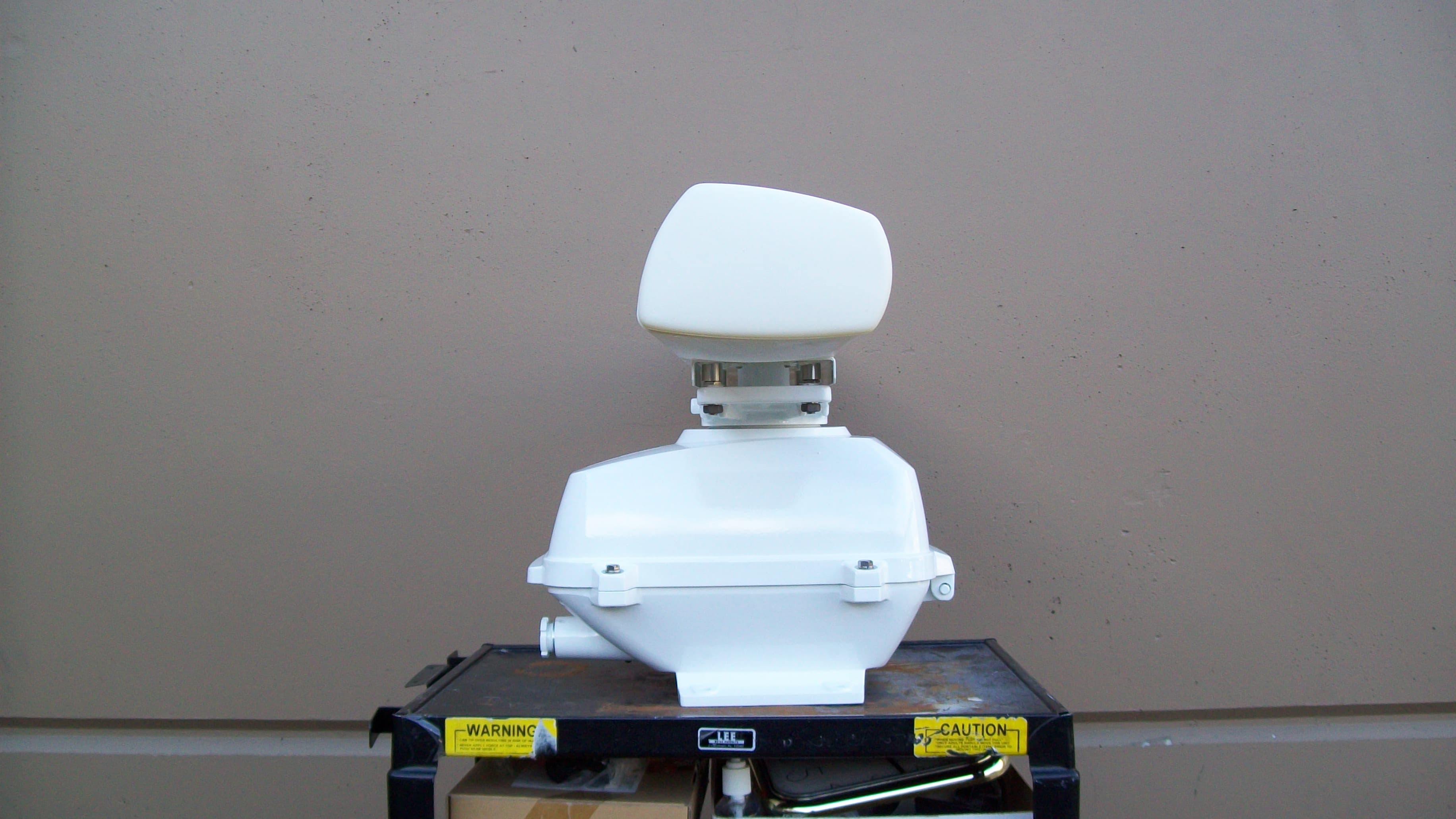
Click to zoom
Application Details
- Equipment Class
- MRD - Marine Radar
- Date of Grant
- Nov 17, 2010
- Application Purpose
- Original Equipment
- Date of Application
- Nov 16, 2010
- Equipment Note
- MARINE RADAR
- Frequency Range
- 9380.00000000 - 9440.00000000
- Company
- Japan Radio Co., Ltd.
- Country
- United States
Documents & Files
Document Text
Text extracted from the exhibit documents filed with the FCC. Open a document above to read the original.
Users Manual
MARINE RADARMARINE RADAR EQUIPMENTEQUIPMENT INSTRUCTIONINSTRUCTION MANUALMANUAL JMA-5208/HSJMA-5208/HSJMA-5212-4/6JMA-5212-4/6JMA-5222-7/9JMA-5222-7/9JMA-5212-4HS/6HSJMA-5212-4HS/6HS 01ETM ISO 9001, ISO 14001 Certified Printed in Japan Marine Service Department [email protected] Telephone :Facsimile :e-mail : AMSTERDAM Branch Telephone :Facsimile :e-mail : [email protected] SEATTLE Branch Telephone :Facsimile :e-mail : [email protected] CODE No.7ZPRD0703 CODE No.7ZPRD0703 FEB. 2010 Edition 3 JRCFEB. 2010 Edition 3 JRC Not use the asbestos For further information,contact: URL http://www.jrc.co.jp ◆◆◆PRECAUTIONS BEFORE OPERATION◆◆◆ ■Cautions for high voltage High voltages from hundreds volts to tens of thousands volts are to be applied to the electronic equipment such radio and radar devices. You do not face any danger during normal operation, but sufficient cares are required for maintenance, inspection and adjustment of their internal components. (Maintenance, check-up and adjustment of the inside of the equipment are prohibited except by maintenance specialists.) High voltages of tens of thousands volts are so dangerous as to bring an instantaneous death from electric shock, but even voltages of hundred volts may sometimes lead to a death from electric shock. To prevent such an accident, make it a rule to turn off the power switch, discharge capacitors with a wire surely earthed on an end make sure that internal parts are no longer charged before you touch any parts inside these devices. At the time, wearing dry cotton gloves ensures you further to prevent such danger. It is also a necessary caution to put one of your hands in the pocket and not to use your both hands at the same time. It is also important to select a stable foothold always to prevent additional injuries once you were shocked by electricity. If you were injured from electric shock, disinfect the burn sufficiently and get it taken care of promptly. ■What to do in case of electric shock When finding a victim of electric shock, turn off the power source and earth the circuit immediately. If it is impossible to turn off the circuit, move the victim away promptly using insulators such as dry wood plate and cloth without touching the victim directly. In case of electric shock, breathing may stop suddenly if current flows to the respiration center in the brain. If the shock is not so strong, artificial respiration may recover breathing. When shocked by electricity, the victim will come to look very bad with weak pulse or without beating, resulting in unconsciousness and rigidity. In this case, it is necessary to perform an emergency measure immediately. ◆◆◆FIRST-AID TREATMENTS◆◆◆ ☆First-aid treatments As far as the victim of electric shock is not in dangerous condition, do not move him and practice artificial respiration on him immediately. Once started, it should be continued rhythmically. (1) Do not touch the victim confusedly as a result of the accident, but the rescuer may also get an electric shock. (2) Turn off the power source calmly and move the victim away quietly from the electric line. (3) Call a physician or ambulance immediately or ask someone to call a doctor. (4) Lay the victim on this back and loosen his necktie, clothes, belt, etc. (5) a. Examine the victim’s pulse. b. Examine his heartbeat bringing your ear close to his heart. c. Examine his breathing bringing the back of your hand or your face close to his face. d. Check the size of the pupils of his eyes. (6) Open the victim’s mouth and take out artificial teeth, cigarette or chewing gum if any. Keep his mouth open, stretch his tongue and insert a towel or the like in his mouth to prevent the tongue from suffocating. (If it is hard to open his mouth due to set teeth, open it with a screwdriver and insert a towel in this mouth.) (7) Then, wipe his mouth so that foaming mucus does not accumulate inside. ☆When pulse is beating but breathing has stopped (Mouth-to-mouth respiration) Fig. 1 (1) Tilt the victim’s head back as far as this face looks back. (A pillow may be inserted his neck.) (2) Push his jaw upward to open his throat wide (to spread his airway). (3) Pinch the victim’s nostrils and take a deep breath, block his mouth completely with yours and blow into his mouth strongly. Take a deep breath again and blow into his mouth. Continue this 10 to 15 times a minutes (blocking his nostrils). (4) Carefully watch that he has recovered his natural breathing and atop practicing artificial respiration. (5) If it is difficult to open the victim’s mouth, insert a rubber or vinyl tube into one of his nostrils and blow into it blocking the other nostril and his mouth completely. (6) When the victim recovers consciousness, he may try to stand up suddenly, but let him lie calmly and serve him with a cup of hot coffee or tea and keep him warm and quiet. (Never give him alcoholic drinks.) Method of mouth-to-mouth respiration by raising head (1) Raise the victim’s head. Support his forehead with one of your hand and his neck with the other hand. →1 When you tilt his head backward, the victim, in most cases, opens his mouth to the air. This makes mouth-to mouth respiration easy. (2) Cover his mouth as widely as possible with yours and press your cheek against his nose →2 or, pinch his nostrils with your fingers to prevent air from leaking. →3 (3) Blow into his lungs. Continue blowing into his mouth until his breast swells. Blow into his mouth as quickly as possible for the first 10 times. Fig. 1 Mouth-to mouth respiration ☆When both pulse and breathing have stopped Perform the (Cardiac massage) Fig. 2 and (Mouth-to-mouth respiration) Fig. 1 When no pulse has come not to be felt, his pupils are open and no heartbeat is heard, cardiac arrest is supposed to have occurred and artificial respiration must be performed. (1) Place your both hands, one hand on the other, on the lower one th…
Text truncated - open the document above for the full version.
Users Manual
SECTION 2 SCREEN DISPLAY AND OPERATION PANEL 2.1 Example of Display................................................................................................... 2-1 2.2 Names and Functions of Control Panel KEYs ....................................................... 2-2 2.3 Functions of Software Buttons ............................................................................... 2-7 2.3.1 Software Buttons for Area 1 (Top-Left Corner of the Radar Display) ........... 2-8 2.3.2 Software Buttons for Area 2 (Bottom-Left Corner of the Radar Display) ... 2-10 2.3.3 Software Buttons for Area 3 (Top-Right Corner of the Radar Display)....... 2-12 2.3.4 Software Buttons for Area 4 (Bottom-Right Corner of the Radar Display)................................................ 2-14 2.3.5 Software Buttons for Area 5 (Own Ship Information Area) (Right Side of the Radar Display) ................ 2-15 2.3.6 Software Buttons for Area 6 (Other Ship Information Area) (Right Side of the Radar Display) .............. 2-16 2.3.7 Software Buttons for Area 7 (Panel Display Area) (Right Side of the Radar Display) .............................. 2-18 2.3.8 Software Buttons for Area 7 (Panel Display Area) (Right Side of the Radar Display) .............................. 2-19 2.3.9 Software Buttons for Area 8 (Operation and Message Area) (Right Side of the Radar Display) .................................................................. 2-20 2─1 2.1 EXAMPLE OF DISPLAY 2.2 NAMES AND FUNCTIONS OF CONTROL PANEL KEYS 2─2 2 y y 2.2 NAMES AND FUNCTIONS OF CONTROL PANEL KEYS The following page describe name of buttons. 2─3 ① Trackball Use this trackball to move the cursor mark to an arbitrary point. The trackball can be used for setting in each mode. For example, use it to specify the center of a floating EBL or the off-center position. →For setting cursor, see section 3.9.3. ② [EBL] (Electric Bearing Line) Control Rotates the bearing of an EBL. The selected EBL status switches back and forth between “center fixed” and “floating” each time the control is pressed. →See section 3.5.2. ③ [VRM] (Variable Range Marker) Control Changes the range of a VRM. →See section 3.5.4. ④ [MULTI] (Multi-function) Control Each time you press this control, you can change items registered in the multi-function control function. An item to switch to is shown put in parentheses in the lower left area of the screen. Give a long press of the control to open the setup screen for registering items. Give a long press of the control button again to close this setup screen. →See section 3.5.18. ⑤ [AUTO-RAIN] (Rain/Snow Clutter Suppression) Control Suppresses the clutter echo from rain or snow. To heighten a suppressing effect, turn the control clockwise. The clutter suppression mode switches back and forth between MANUAL and AUTO each time the control is pressed. →See section 3.4.7. ⑥ [AUTO-SEA] (Sea Clutter Suppression) Control Suppresses the clutter echo from the sea surface. To heighten a suppressing effect, turn the control clockwise. The clutter suppression mode switches back and forth between MANUAL and AUTO each time the control is pressed. →See section 3.4.6. ⑦ [GAIN/PL] (Receiving Sensitivity/Pulse Width) Control Controls the radar’s receiving sensitivity. To get higher sensitivity, turn the control clockwise. To change the transmitter pulse width, press the control. →For sensitivity, see section 3.4.5. →For pulse width, see section 3.5.11. ⑧ [STBY] (Standby) Key Use this key to change the power-off state to the power-on state, or the transmission state to the standby state. To turn off the power, press the [STBY] key and [TX/PRF] key together. →See section 3.4.2. 2.2 NAMES AND FUNCTIONS OF CONTROL PANEL KEYS 2─4 2 y y ⑨ [TX/PRF] (Transmit/Transmitting Repetition Frequency) Key PREHEAT at the upper left of the radar display changes to STANDBY about three minutes after the power is turned on. Then, press this key to start transmission. To fine-tune the transmitting repetition frequency, press the key during transmission. Use of this function with the interference rejection function heightens an interference suppressing effect. →See section 3.4.1. ⑩ [EBL1] (Electric Bearing Line 1) Key Use this key to display and select EBL1. Holding down the key for two seconds or more displays the menu for EBL1 setting. →See section 3.5.2. →For EBL1 setting, see section 3.5.3. ⑪ [EBL2] (Electric Bearing Line 2) Key Use this key to display and select EBL2. Holding down the key for two seconds or more displays the menu for EBL2 setting. →See section 3.5.2. →For EBL2 setting, see section 3.5.3. ⑫ [ALARM ACK] (Alarm Acknowledgment) Key Use this key to acknowledge a failure, target’s approach, or collision alarm. Press the key to stop an audible alarm. If more than one alarm has occurred, the key needs to be pressed the number of times equivalent to the number of alarms. →See section 3.3.7. ⑬ [PANEL] (Operation Panel Brilliance) Key Controls the brilliance for the controls and Keys on the operation panel. The brilliance changes cyclically each time the key is pressed. →See section 3.3.3. ⑭ [MOB] (Marker) Key A marker is set to the latitude and longitude of the own ship’s position at the point of pressing this key. For example, use the key to store the own ship’s position at the moment when somebody falls from the ship. Holding down the key for two seconds or more erases the marker. →See section 3.5.15. ⑮ [ACQ] (Manual Acquisition) Key Enables the manual TT acquisition mode for the target on which the cursor sits. →See section 5.2.1. ⑯ [TGT CNCL] (Tracking Target Cancel) Key Cancels the symbol and vector of a target under tracking, and stops tracking the target. Holding down the key for two seconds or more erases all the acquisitions of TT. →See section 5.2.2. ⑰ [TGT DATA] (Target Data Setup) Key Use this key to view the numeric data of the TT under tracking or the currently displayed AIS. →See section 5.2.3. 2─5 ⑱ [FUNC] (Function Call) Key Calls predefined sign…
Text truncated - open the document above for the full version.
Users Manual
3.8 DISPLAY NAVIGATION INFORMATION (NEW INFORMATION DISPLAY) 3─84 3 y y y 3.8 DISPLAY NAVIGATION INFORMATION (NAV INFORMATION DISPLAY) Navigation information such as waypoint marks, and a maximum of 256 points of NAV lines, coastlines, depth contours, and NAV marks can be displayed, created, read, saved, corrected, and deleted. (This function is available only when navigation equipment is connected with the system.) Note: Navigation information is available between latitudes of 85ºN and 85ºS. 3.8.1 Display Waypoint Marks (Waypoint Display) When waypoint information is received from the navigation equipment, the waypoint mark appears on the radar display. In this case, ◎W is indicated as the waypoint mark on the radar display. Procedure 1 Press [RADAR MENU] key twice. Press [6] key. The NAV Information Menu will appear. 2 Press [1] key. The setting of Waypoint Display will be switched between ON and OFF. ON : Displays waypoint marks. OFF : Does not display waypoint marks. Waypoint marks are displayed only when NMEA sentences are used to receive Waypoint information. A plotter function (option) is needed to make Waypoint in this radar. 3─85 3.8.2 Display Navigation Information (NAV Display Setting) The navigation information below can be displayed (ON) or hidden (OFF) individually. c Line 1 [Line 1] ― d Line 2 [Line 2] ---- e Line 3 [Line 3] ‐― f Mark 1 [Mark 1] g Mark 2 [Mark 2] ★ h Mark 3 [Mark 3] + i Mark 4 [Mark 4] Y Procedure 1 Press [RADAR MENU] key. Press [6] key. Press [2] key. The NAV Display Setting Menu will appear. To determine whether to display each type of navigation information, press the corresponding numeric key. ON : Displays the navigation information. OFF : Does not display the navigation information. 3.8 DISPLAY NAVIGATION INFORMATION (NEW INFORMATION DISPLAY) 3─86 3 y y y 3.8.3 Create/Edit Navigation Information (Edit User Map) Procedure 1 Press [RADAR MENU] key. Press [6] key. Press [3] key. Press [6] key. The Edit User Map Menu will appear. The Edit User Map enables the operations of the functions below. Clear Map Object: Clears all or an item of navigation information. Make Map Object: Creates navigation information. Correct: Corrects navigation information. Delete: Deletes one point from navigation information. Insert: Inserts an element into a line of each type 3─87 1 Clearing all or an item of navigation information (Clear Map Object) Procedure 1 Press [1] key while the Edit User MAP Menu is open. The Clear Map Object Menu will appear. Select the type of navigation information to be cleared, pressing the corresponding numeric key. Line1: Clears Line 1. Line2: Clears Line 2. Line3: Clears Line 3. Mark1: Clears Mark 1. Mark2: Clears Mark 2. Mark3: Clears Mark 3. Mark4: Clears Mark 4. All: Clears all items of navigation information. 3.8 DISPLAY NAVIGATION INFORMATION (NEW INFORMATION DISPLAY) 3─88 3 y y y 2 Making navigation information (Make Map Object) Procedure 1 Press [2] key while the Edit User MAP Menu is open. The Make Map Object Menu will appear. MAKE will appear in the CURSOR mode field at software button ② located at the bottom right corner of the radar display described in Section 2.3.3. 2 Select the type of navigation information to be made, pressing the corresponding numeric key. 3 Use the trackball to move the cross cursor mark to the starting point of a line or a point where a mark is to be made, and press [ENT] key. The starting point of a line or one point of a mark will be determined. 4 Repeat step 3, and press [8] key when finishing the making of the line or mark. The line or mark make mode will terminate. 5 To make another line or mark, repeat steps 2 to 4. 6 Press [0] key when finishing the making of all navigation information. The Edit User Map Menu will reappear. Note: Navigation information can be created with a maximum of 256 points being plotted. The number of points that can still be plotted (REMAIN POINT in the menu) is decremented each time a line or mark is plotted. 3─89 3 Correcting a continuous line or moving a mark (Correct) Procedure 1 Press [3] key while the Edit User Map Menu is open. The navigation information correction mode will be activated. Correct will appear in the CURSOR mode field at software button ② located at the bottom right corner of the radar display described in Section 2.3.3. 2 Use the trackball to move the pointer to the vertex in a line to be corrected or the mark to be moved, and press [ENT] key. The cross cursor mark will appear on the selected line or mark. 3 Use the trackball to move the cross cursor mark to a new point to which the line is corrected or the mark is moved. The selected line will be corrected to the new point, or the mark will be moved there. 4 To correct another line or mark, repeat steps 2 and 3. 5 Press [0] key when finishing the correction of lines and marks. The CURSOR mode at the upper right of the radar display will change to the general operation mode, terminating the navigation information correction mode. (Example) Select a top 3.8 DISPLAY NAVIGATION INFORMATION (NEW INFORMATION DISPLAY) 3─90 3 y y y 4 Deleting a continuous line or mark (Delete) Procedure 1 Press [4] key while the Edit User Map Menu is open. The navigation information deletion mode will be activated. Delete will appear in the CURSOR mode field at software button ② located at the top right corner of the radar display described in Section 2.3.3. 2 Use the trackball to move the pointer to the vertex in a line or the mark to be deleted, and press [ENT] key. The selected line or mark will be deleted. Note: A line drawn by joining two points is all deleted. 3 To delete another line or mark, repeat step 2. 4 Press [0] key when finishing the deletion of lines and marks. The CURSOR mode at the upper right of the radar display will change to the general operation mode, terminating the navigation information deletion mode. (Example) Deletion of a vertex from a line 3─91 5 Inserting a vertex into a line (Insert) Procedure 1 Pr…
Text truncated - open the document above for the full version.
Users Manual
7─11 7.2 NAVIGATOR SETTING This section describes the electrical adjustment procedures to be performed by service engineers during system installation. Make an appropriate setting for each type of equipment when inputting true bearing signals, true bearing data, and speed data. Settings and parameters are different for each type of equipment. Make settings for the type of equipment to be connected. [I] Inputting analog true bearing signals from a gyro system through synchronization and steps By following the procedure described in the INSTALLATION MANUAL, connect the optional NSK unit (NCT-4106A) to this equipment. Then, follow the steps below to make settings. In Section 7.2.1 “Ship Heading Equipment Setting (Heading Equipment),” select 1: GYRO (NCT-4106A, JLR10, JRL20/30). By referring to Section 7.2.2 “NSK Unit Setting,” make a setting for the gyro system. By referring to Section 7.2.3 “True Bearing Value Setting (Set GYRO),” make a setting such that the gyro azimuth and the radar azimuth are the same. Refer to an applicable page for details. CAUTION Do not carry out the adjustments of the equipment except authorized service persons. If wrong setting is carried out, this may cause unstable operation. Do not carry out the adjustments during navigation. Otherwise, the radar performance may be affected, resulting in an accident or trouble. 7.2 NAVIGATOR SETTING 7─12 7 yyy yyyy [II] Inputting digital true bearing signals from a gyro system (IEC61162, NMEA0183) By following the procedure described in the INSTALLATION MANUAL, connect the gyro system to this equipment. Then, follow the steps below to make settings. In Section 7.2.1 “Ship Heading Equipment Setting (Heading Equipment),” select 2: COMPASS (IEC61162). In Section 7.3.1.1 “Baud Rate Setting,” select 5. COM5 (COMPASS). Select either 38400 bps or 48000 bps depending on the data baud rate outputted from the GPS compass. (*) For digital signal output from the gyro system ・ Select 38400 bps if possible. A higher baud rate means shorter data output cycle, which results in better course following performance. ・ If the system allows setting of data output cycle, set it to 10 ms to 20 ms. A longer data output cycle results in lower course following performance. This may affect the radar performance level and the target tracking performance level. Refer to an applicable page for details. [III] Inputting true bearing data from GPS Compass JLR10 or JLR20/30 By following the procedure described in the INSTALLATION MANUAL, connect GPS Compass JLR10 or JLR20/30 to this equipment. Then, follow the steps below to make settings. In Section 7.2.1 “Ship Heading Equipment Setting (Heading Equipment),” select 1: GYRO (NCT-4106A, JLR10, JRL20/30). True bearing value setting described in Section 7.2.3 is not required when using the GPS compass. If the GPS compass azimuth and the radar azimuth are not the same, use the GPS compass to adjust the azimuth. Refer to an applicable page for details. [IV] Inputting digital true bearing data from a GPS compass (other than JLR10 and JLR20/30) or other true bearing systems (IEC61162 or NMEA0183) By following the procedure described in the INSTALLATION MANUAL, connect a GPS compass or other true bearing system to this equipment. Then, follow the steps below to make settings. In Section 7.2.1 “Ship Heading Equipment Setting (Heading Equipment),” select 2: COMPASS (IEC61162). In Section 7.3.1.1 “Baud Rate Setting,” select 5. COM5 (COMPASS). Select either 38400 bps or 48000 bps depending on the data baud rate outputted from the GPS compass. (*) For the GPS compass or other true bearing systems ・ Select 38400 bps if possible. A higher baud rate means shorter data output cycle, which results in better course following performance. ・ If the system allows setting of data output cycle, set it to 10 ms to 20 ms. A longer data output cycle results in lower course following performance. This may affect the radar performance level and the target tracking performance level. Refer to an applicable page for details. 7─13 [V] Inputting analog speed signals from a log system through synchronization and steps By following the procedure described in the INSTALLATION MANUAL, connect the optional NSK unit (NCT-4106A) to this equipment. Then, follow the steps below to make settings. In Section 7.2.5 “Ship Speed Equipment Setting (Speed Equipment),” select 2: LOG. Refer to an applicable page for details. [VI] Inputting digital speed data using a current meter or a Doppler sonar (IEC61162 or NMEA0183) By following the procedure described in the INSTALLATION MANUAL, connect speed equipment to this equipment. Then, follow the steps below to make settings. In Section 7.2.5 “Ship Speed Equipment Setting (Speed Equipment),” select 3: 2 AXIS W to use the sea speed. Select 4: 2 AXIS G to use the ground speed. Refer to an applicable page for details. [VII] Inputting GPS speed data (IEC61162 or NMEA0183) By following the procedure described in the INSTALLATION MANUAL, connect speed equipment to this equipment. Then, follow the steps below to make settings. In Section 7.2.5 “Ship Speed Equipment Setting (Speed Equipment),” select 5: GPS. Refer to an applicable page for details. [VIII] Inputting speed data manually In Section 7.2.5 “Ship Speed Equipment Setting (Speed Equipment),” select 1: Manual. In Section 7.2.6 “Manual Speed Setting (Manual Speed),” input the speed manually using the numeric keypad or multi-dial. Refer to an applicable page for details. 7.2 NAVIGATOR SETTING 7─14 7 yyy yyyy 7.2.1 Ship Heading Equipment Setting (Heading Equipment) Procedure 1 Press [RADAR MENU] key. Main Menu opens. 2 Press [7] key. NAV Equipment Setting menu opens. 3 Press [2] key. Heading Equipment settings are displayed. 4 From the pull-down menu, select heading equipment. 1 : GYRO (NCT-4106A, JLR10, JLR20/30) 2 : COMPASS (IEC61162) <The alternative procedure for steps above> 1 Hold down [RADAR MENU] key. The Code Input Menu will appear. 2 Press [0] key. 3 Move…
Text truncated - open the document above for the full version.
Cover Letter(s)
SEATTLE BRANCH 1021 SW Klickitat Way, Bldg. D, Suite 101 · Seattle WA 98134 Tel: (206) 654-5644 · Fax: (206) 654-7030 Federal Communications Commission Authorization and Evaluation Division Confidentiality Request regarding application for certification of FCC ID: CKENKE2062. Pursuant to Sections 0.457 and 0.459 of the Commission’s Rules, we hereby request confidential treatment of information accompanying this application as outlined below: Exhibit Type File Name Block Diagrams Schematics Operational Description Tune Up Procedures Parts List CKENKE2062 BlkDia.pdf CKENKE2062 Schem.pdf CKENKE2062 OpDes.pdf CKENKE2062 TunPro.pdf CKENKE2062 PartsLst.pdf The above materials contain trade secrets and proprietary information not customarily released to the public. The public disclosure of these materials may be harmful to the applicant and provide unjustified benefits to its competitors. The applicant understands that pursuant to Section 0.457 of the Rules, disclosure of this application and all accompanying documentation will not be made before the date of the Grant for this application. Pursuant to DA04-1705 June 15, 2004 of the Commission’s public notice, we also request temporary confidential treatment of information accompanying this application as outlined below: Exhibit Type File Name External Photos Internal Photos CKENKE2062 ExtPho.pdf CKENKE2062 IntPho.pdf Sincerely, Eric D’Ancicco Service Manager Japan Radio Co., Ltd.
Test Report
1. SYSTEM DESCRIPTION ★NKE-2062 Type of Unit: Scanner unit The MTR is installed within a 4 feet scanner unit. The scanner weight is approximately 24kg. The antenna is rotated 27 rpm by its driving motor. This has a 2 degrees horizontal beam width and 30 degrees for vertical. The transmitter operates with 4-pulse length and 4-pulse repetition frequencies. The magnetron, MSF1422B, rated output is 6kw and is driven by solid-state modulator. The receiver has a microwave front end, containing the low noise amplifier, mixer, local oscillator, IF amplifier and detector. GENERAL SPECIFICATION 1. Dimensions: Height: 432mm, Swing circle: 120mm 2. Mass: Approx. 24kg 3. Polarization: Horizontal 4. Beam width Horizontal (-3dB): 2 degree Vertical (-3dB): 30 degree Side lobe level: Less than -23dB within 10 degree of main beam other than -26dB within 10 degree of main beam 5. Rotation speed: Approx. 27rpm 6. Frequency: 9410±30MHz 7. Peak Power: 6kW 8. Pulse length / Repetition frequency: 0.08us/2250Hz, 025us/1700Hz, 05us/1200Hz, 1.0us/650Hz 9. Modulator: Solid-state modulator 10. Duplexer: Circulator / Diode Limiter 11. Front end module; Built in 12. IF amplifier: Logarithmic amplifier, Noise figure 6dB maximum. 13. Tunin: Manual / Auto 3. TEST RESULTS SUMMARY 3.1 Mechanical Tests Appearance and Structure Scanner Unit Good 3.2 Electrical Tests 3.2.1 Working of each operation unit Scanner Unit Good 3.2.2 Scanner VSWR frequency (MHz) VSWR 9380 1.02 9410 1.03 9440 1.04 9441 Scanner Rotation Speed 27 /48 rpm 3.2.3 Transmitter Magnetron Ser. No. SJ2B/F5769C Operating Frequency (at 0.08 μs pulse, SP) 9428.7 MHz (at 0.25 μs pulse, MP1) 9428.7 MHz (at 0.5 μs pulse, MP2) 9428.7 MHz (at 1.0 μs pulse, LP) 9428.0 MHz RF power output (Mean power) (at 0.08 μs pulse, SP) 0.11 W (at 0.25 μs pulse, MP1) 1.41 W (at 0.5 μs pulse, MP2) 3.72 W (at 1.0 μs pulse, LP) 7.94 W Pulse Length (at 0.08 μs pulse, SP) 0.088 μs (at 0.25 μs pulse, MP1) 0.248 μs (at 0.5 μs pulse, MP2) 0.470 μs (at 1.0 μs pulse, LP) 1.020 μs Repetition Frequency (0.08μs) 2251 Hz (0.25μs) 1704 Hz (0.5 μs) 1205 Hz (1.0 μs) 651 Hz Spurious Emission at Antenna Terminal Good Field strength of spurious radiation Good Radiofrequency radiation exposure limits Good 3.2.4 Receiver MIC Front-end Ser. No. C2862A Diode limiter Ser. No. X0847A IF Center Frequency 60 MHz IF Bandwidth 20/6/3 MHz 3.2.5 Input Voltage and Current(at 24NM-LP1) DC.24V 1.86A(44.64W) 3.3 Overall Tests Working Time of Timer 1min30sec Input Variation (21.6Vdc – 42Vdc) Good Overall Sensitivity Good Minimum Range Good Bearing Accuracy Good Mechanical Noise Good 4.1 RF Power Output 47 CFR sec. 2.1046 4.1.1 TEST SETUP 4.1.2 TEST INSTRUMENTS DESCRIPTION & MANUFACTURER MODEL NO. SERIAL NO. CALIBRATION DATE CALIBLATION DUE DATE 1 Double Ridge Horn Antenna ETS LINDGREN 3117 00091928 NA NA 2 Adaptor HP X281A NA NA NA 3 Direction Coupler (30dB) SHIMADARIKA 5D363 R11421 NA NA 4 Dummy Load PASTERNACK PE6815 NA NA NA 5 High Power Dummy Load PASTERNACK PE6824 NA NA NA 6 Variable Attenuator HP X382A 1005-00684 May. 2010 May. 2011 7 Adaptor HP X281A NA NA NA 8 Coaxial Cable HUBER+SUHNER SUCOFLEX 104PA 5784 /4PA NA NA 9 Spectrum Analyzer Agilent E4448A MY46180420 Sep. 24. 2010 Sep. 2011 4.1.3 TEST PROCEDURES Reference to Section 2.2.17 Radiated Power Output on TIA-603-C. 4.1.4 EUT OPERATING CONDITIONS a. Placed the EUT on the testing table. b. Prepared other computer systems for controlling EUT and placed them outside of testing area. c. EUT can be transmitted four pulses are 0.08usec/2250Hz, 0.25usec/1700Hz, 0.5usec/1200Hz and 1.0usec/650Hz. 4.1.5 TEST RESULTS The radiated power output is calculated by the following: iatedaverageraddBmpower i i LOSSLVLi )108/1log(10 8 1 10 ∑ = = + = Pulse Length [usec] 0.08 0.25 0.5 1.0 PRF [Hz] 2250 1700 1200 650 averageradiated power [dBm] 20.4 31.5 35.7 39.0 i LVL [dBm] LVL + LOSS [dBm] LVL [dBm] LVL + LOSS [dBm] LVL [dBm] LVL + LOSS [dBm] LVL [dBm] LVL + LOSS [dBm] 1 -35.21 20.59 -24.4231.38 -19.9835.82 -17.3338.47 2 -34.95 20.85 -24.3431.46 -20.2135.59 -16.5639.24 3 -35.59 20.21 -24.4531.35 -19.9535.85 -17.0538.75 4 -35.53 20.27 -24.2531.55 -20.2235.58 -17.0138.79 5 -35.58 20.22 -24.1931.61 -20.1735.63 -16.8738.93 6 -35.56 20.24 -24.3931.41 -20.235.6 -16.8338.97 7 -35.32 20.48 -24.3431.46 -19.9735.83 -16.3439.46 8 -35.33 20.47 -24.1931.61 -2035.8 -16.8438.96 *LOSS = 55.80dB 4.1.6 TEST CONDITIONS Tamb = 20°C to 25°C, RHamb = 40% ~ 60% EUT input = 24 VDC 4.1.7 STABILLIZATION EUT energized for 10 minutes minimum. 4.1.8 TEST EQUIPMENT JRC Original – Shielded …
Text truncated - open the document above for the full version.
Contact Information
Applicant
Yuji Kinoshita(General Manager)
Test Firm
Japan Radio Co., Ltd.Mitsuru Okamoto
Technical Specifications
| # | Rule Parts | Frequency Range | Power Output | Emission | Tolerance |
|---|---|---|---|---|---|
| 1 | 80 | 9.38 GHz - 9.44 GHz | 6000 W | 53M3P0N | 3000.0000000000 Hz |
Other Applications from Japan Radio Co., Ltd.

CKENTG1014
May 09, 20235G Radio Unit
Equipment Class
CBD - Citizens Band Category A and B Devices
CKENKE2632
Oct 21, 2015Solid State S-Band Marine Radar
Equipment Class
MRD - Marine Radar
CKENJJ-200
Jan 22, 2015Handy Search
Equipment Class
UWB - Ultra Wideband Transmitter
CKEJRN-130K
Oct 21, 20143G/GSM IT Controller
Equipment Class
PCB - PCS Licensed Transmitter
CKENKE1066
Feb 04, 2014MARINE RADAR
Equipment Class
MRD - Marine Radar