CKENKE3710MARINE RADAR
Japan Radio Co., Ltd.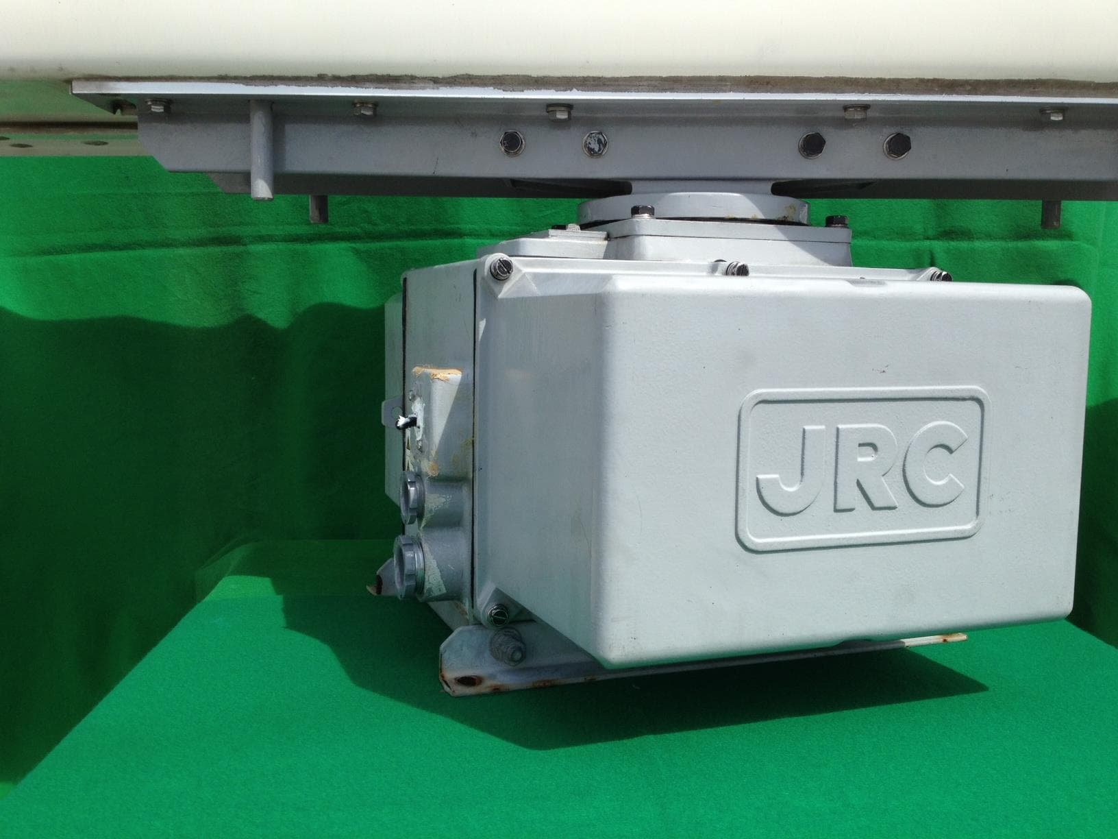
Click to zoom
Application Details
- Equipment Class
- MRD - Marine Radar
- Date of Grant
- Nov 14, 2013
- Application Purpose
- Original Equipment
- Date of Application
- Nov 14, 2013
- Equipment Note
- MARINE RADAR
- Frequency Range
- 3025.00000000 - 3075.00000000
- Company
- Japan Radio Co., Ltd.
- Country
- United States
Documents & Files
Document Text
Text extracted from the exhibit documents filed with the FCC. Open a document above to read the original.
Users Manual
MARINE RADARMARINE RADAR EQUIPMENTEQUIPMENT INSTRUCTIONINSTRUCTION MANUALMANUAL JMA-5352-9RJMA-5352-9RJMA-5362-8RJMA-5362-8R 01ETM ISO 9001, ISO 14001 Certified Printed in Japan Marine Service Department [email protected] Telephone :Facsimile :e-mail : AMSTERDAM Branch Telephone :Facsimile :e-mail : [email protected] SEATTLE Branch Telephone :Facsimile :e-mail : [email protected] CODE No.7ZPRD0811 CODE No.7ZPRD0811 APR. 2010 Edition 2 JRCAPR. 2010 Edition 2 JRC Not use the asbestos For further information,contact: URL http://www.jrc.co.jp ◆◆◆PRECAUTIONS BEFORE OPERATION◆◆◆ ■ Cautions for high voltage High voltages from hundreds volts to tens of thousands volts are to be applied to the electronic equipment such radio and radar devices. You do not face any danger during normal operation, but sufficient cares are required for maintenance, inspection and adjustment of their internal components. (Maintenance, check-up and adjustment of the inside of the equipment are prohibited except by maintenance specialists.) High voltages of tens of thousands volts are so dangerous as to bring an instantaneous death from electric shock, but even voltages of hundred volts may sometimes lead to a death from electric shock. To prevent such an accident, make it a rule to turn off the power switch, discharge capacitors with a wire surely earthed on an end make sure that internal parts are no longer charged before you touch any parts inside these devices. At the time, wearing dry cotton gloves ensures you further to prevent such danger. It is also a necessary caution to put one of your hands in the pocket and not to use your both hands at the same time. It is also important to select a stable foothold always to prevent additional injuries once you were shocked by electricity. If you were injured from electric shock, disinfect the burn sufficiently and get it taken care of promptly. ■ What to do in case of electric shock When finding a victim of electric shock, turn off the power source and earth the circuit immediately. If it is impossible to turn off the circuit, move the victim away promptly using insulators such as dry wood plate and cloth without touching the victim directly. In case of electric shock, breathing may stop suddenly if current flows to the respiration center in the brain. If the shock is not so strong, artificial respiration may recover breathing. When shocked by electricity, the victim will come to look very bad with weak pulse or without beating, resulting in unconsciousness and rigidity. In this case, it is necessary to perform an emergency measure immediately. ◆◆◆FIRST-AID TREATMENTS◆◆◆ ☆ First-aid treatments As far as the victim of electric shock is not in dangerous condition, do not move him and practice artificial respiration on him immediately. Once started, it should be continued rhythmically. (1) Do not touch the victim confusedly as a result of the accident, but the rescuer may also get an electric shock. (2) Turn off the power source calmly and move the victim away quietly from the electric line. (3) Call a physician or ambulance immediately or ask someone to call a doctor. (4) Lay the victim on this back and loosen his necktie, clothes, belt, etc. (5) a. Examine the victim’s pulse. b. Examine his heartbeat bringing your ear close to his heart. c. Examine his breathing bringing the back of your hand or your face close to his face. d. Check the size of the pupils of his eyes. (6) Open the victim’s mouth and take out artificial teeth, cigarette or chewing gum if any. Keep his mouth open, stretch his tongue and insert a towel or the like in his mouth to prevent the tongue from suffocating. (If it is hard to open his mouth due to set teeth, open it with a screwdriver and insert a towel in this mouth.) (7) Then, wipe his mouth so that foaming mucus does not accumulate inside. ☆ When pulse is beating but breathing has stopped (Mouth-to-mouth respiration) Fig. 1 (1) Tilt the victim’s head back as far as this face looks back. (A pillow may be inserted his neck.) (2) Push his jaw upward to open his throat wide (to spread his airway). (3) Pinch the victim’s nostrils and take a deep breath, block his mouth completely with yours and blow into his mouth strongly. Take a deep breath again and blow into his mouth. Continue this 10 to 15 times a minutes (blocking his nostrils). (4) Carefully watch that he has recovered his natural breathing and atop practicing artificial respiration. (5) If it is difficult to open the victim’s mouth, insert a rubber or vinyl tube into one of his nostrils and blow into it blocking the other nostril and his mouth completely. (6) When the victim recovers consciousness, he may try to stand up suddenly, but let him lie calmly and serve him with a cup of hot coffee or tea and keep him warm and quiet. (Never give him alcoholic drinks.) Method of mouth-to-mouth respiration by raising head (1) Raise the victim’s head. Support his forehead with one of your hand and his neck with the other hand. →1 When you tilt his head backward, the victim, in most cases, opens his mouth to the air. This makes mouth-to mouth respiration easy. (2) Cover his mouth as widely as possible with yours and press your cheek against his nose →2 or, pinch his nostrils with your fingers to prevent air from leaking. →3 (3) Blow into his lungs. Continue blowing into his mouth until his breast swells. Blow into his mouth as quickly as possible for the first 10 times. Fig. 1 Mouth-to mouth respiration ☆ When both pulse and breathing have stopped Perform the (Cardiac massage) Fig. 2 and (Mouth-to-mouth respiration) Fig. 1 When no pulse has come not to be felt, his pupils are open and no heartbeat is heard, cardiac arrest is supposed to have occurred and artificial respiration must be performed. (1) Place your both hands, one hand on the other, on the lower one third area of his breastbone and compress his breast wi…
Text truncated - open the document above for the full version.
Users Manual
SECTION 3 BASIC OPERATION 3.1 OPERATION FLOW .......................................................................... 3-1 3.2 OBSERVE AND ADJUST VIDEO ..................................................... 3-5 3.3 OPERATION PROCEDURES ......................................................... 3-12 3.4 GENERAL RADAR OPERATION ................................................... 3-22 3.5 USE OWN SHIP'S TRACK DATA ................................................... 3-50 3.6 DISPLAY USER MAP...................................................................... 3-55 3.7 USE ROUTE FUNCTION ................................................................ 3-79 3.8 APPLIED OPERATIONS ................................................................. 3-80 3.9 USE FUNCTION KEY [FUNC] ........................................................ 3-95 3.10 USE USER SETTING.................................................................... 3-101 3.11 USING CARD ................................................................................ 3-103 3.12 DISPLAY SIMPLE CHART ........................................................... 3-109 3.13 CAPTURE SCREEN TO CARD .................................................... 3-122 3-1 3.1 OPERATION FLOW Each operation is described in detail below. z Do not put anything on the operation panel. If you put anything hot on it, it may be deformed. z Do not give any impact to the operation panel, trackball, or controls. Otherwise, any failure or damage may result. Attention POWER ON AND START THE SYSTEM OBSERVE AND ADJUST VIDEO ACQUIRE AND MEASURE DATA END THE OPERATION AND STOP THE SYSTEM 3-2 3.1 Operation Flow y yy 3 z Wait for about 2 seconds before turning on the power again. z Immediately after the radar is installed, at start of the system after it has not been used for a long time, or after the magnetron is replaced, preheat the equipment in the standby state for 20 to 30 minutes before setting it into the transmit state. z If the preheating time is short, the magnetron causes sparks, resulting in its unstable oscillation. Start transmission on a short-pulse range and change the range to the longer pulse ranges in turn. If the transmission is unstable in the meantime, immediately place the system back into the standby state and maintain it in the standby state for 5 to 10 minutes before restarting the operation. Repeat these steps until the operation is stabilized. 3.1.1 Power ON and Start the System CAUTION A malfunction may occur if the power in the ship is instantaneously interrupted during operation of the radar. In this case, the power should be turned on again. Attention 3-3 Procedures 1 Check that the ship’s mains are turned on. 2 Press the [STBY] key. The system is turned on, and the preheating time is displayed. Preheat is indicated upper left of the display. 3 Wait until the preheating time is over. When the preheating time is over, the preheating time screen disappears, and Preheat upper left of the display changes to Standby . 4 Press the [TX / PRF] key. The radar will start transmission and the antenna will start rotating. Standby upper left of the display changes to Transmit . Note: The radar does not start transmission if you Press the [TX / PRF] key while Preheat is indicated. 3.1.2 Observe and Adjust Video Procedures 1 Press the [RANGE+] key or [RANGE-] key to set the range to the scale required for target observation. 2 Turn the dials [GAIN / PL], [AUTO-SEA], and [AUTO-RAIN] to obtain the clearest targets. Refer to [GAIN/PL]→3-7P [AUTO-SEA]→3-8P [AUTO-RAIN]→3-10P for how to use each dial. For how to adjust video, see Chapter 3.2. 3.1.3 Acquire and Measure Data For details on how to acquire data and measure, see Section 4 "Measurement of range and bearing." 3.1.4 Display and Measure with Reference to CCRP The radar video, range, bearing, Target Tracking and AIS data display etc... are displayed with reference to CCRP (Consistent Common Reference Point). If scanner is switched, these data are measured from CCRP. If some kind of functions set scanner position to outside of the PPI range, these data except Target Tracking and AIS data are displayed with reference to scanner position. For how to setting CCRP, see the section 7.1.9. 3-4 3.1 Operation Flow y yy 3 3.1.5 End the Operation and Stop the System Exit 1 Press the [STBY] key. The radar will stop transmission and the antenna will stop rotating. Transmit upper left of the display changes to Standby . Maintain the standby state if radar observation is restarted in a relatively short time. Only pressing the [TX / PRF] key starts observation. 2 Press the [STBY] key and the [TX / PRF] key together. The system will be turned off. 3-5 3.2 OBSERVE AND ADJUST VIDEO 3.2.1 Adjust Monitor Brilliance [BRILL] Procedures 1 Obtain the best-to-see display with optimum brilliance by turning the [BRILL] dial at the lower right of the LCD monitor. Turning the [BRILL] dial clockwise increases the brilliance of the entire display. Conversely, turning the [BRILL] dial counterclockwise decreases the brilliance of the entire display. In consideration of the ambient brightness, adjust display brilliance that is high enough to easily observe the radar display but does not glare. 3.2.2 Change Observation Range [RANGE + / - ] Procedures 1 When increasing the observation range, press the [RANGE+] key. Increasing the observation range will enable a wider range to be observed. However, a video image is small and the ability to detect targets near own ship decreases. Therefore, when observing the vicinity of own ship, use the smaller observation range. 2 When decreasing the observation range, press the [RANGE-] key. Decreasing the observation range will enable the vicinity of own ship to be enlarged. However, caution must be taken because video images of the area beyond the observation range cannot be displayed. 3-6 3.2 Observe and Adjust Video y yy 3 3.2.3 Tune CAUTION Normally, use the automatic tune mode. Use the manual tune …
Text truncated - open the document above for the full version.
Users Manual
SECTION 4 MEASUREMENT OF RANGE AND BEARING 4.1 USE OF NAVIGATION TOOLS ........................................................... 4-1 4.2 MEASUREMENT OF RANGE AND BEARING ................................ 4-17 4-1 4.1 USE OF NAVIGATION TOOLS The system is equipped with the navigation tools below. Cursor Specifies an arbitrary point, and measures the range and bearing from the own ship. Range Rings Displays concentric circles with own ship's position as the center at specified intervals, and the rings are used as rough guides for range measurement. Electronic Bearing Line (EBL1/2) Displays a straight line for specifying an arbitrary bearing, and measures the bearing from the own ship. The process unit is equipped with two electronic bearing lines. Variable Range Marker (VRM1/2) Displays a circle for specifying an arbitrary range, and measures the range from the own ship. The process unit is equipped with two variable range markers. Parallel Index Line (PI) Displays straight lines at even intervals, and the lines are used as rough guides for complex measurement or ship courses. EBL Maneuver Displays the course by steering the own ship, and it is used as a rough guide for ship maneuvering. Man Overboard Stores the latitude and longitude where the own ship was at the point of storing the markers, and shows an anchor symbol on the radar display. When the own ship has moved, the system displays the range and bearing to the position. Use this tool when the ship is anchored or man overboard. EBL/VRM/PI Operation with Cursor (Cursor AUTO) Operates EBL, VRM, or PI on the radar display by using the cursor. 4-2 4.1 Use of Navigation Tools y yyy 4 4.1.1 Using Cursor (Cursor) Procedures 1 Move the cursor onto the PPI display by moving the trackball. When the cursor is moved onto the PPI display, the arrow cursor turns into a cross cursor. 4.1.2 Using Range Rings [RR / HL] Procedures 1 Press the [RR / HL] key. The range ring display switches disappear and appear between display and non-display each time the [RR / HL] key is pressed. The range ring interval is shown in the Range Rings display on / off (upper left of the display ② on page 2-16). The range between the target and own ship can be determined by visually measuring the target's position that lies between two range rings. For change of the brilliance of range rings, refer to Section 3.8.5. 4-3 4.1.3 Using Electronic Bearing Line (EBL1/EBL2) Electronic bearing lines (EBL) are indispensable to the measurement of bearings. Operators must be familiar with the operation of EBL beforehand. The system is equipped with two EBL. The bearing and starting point of an EBL can be operated separately from the other EBL. An intersection marker is displayed at the intersection point of the EBL and VRM of the same number. Intersection markers shown on EBL: : EBL1, VRM1 : EBL2, VRM2 EBL Bearing Display The bearing value of the current EBL1 or EBL2 on the PPI display is shown in the EBL1/2 bearing (upper right of the display on page 2-3). The currently operable EBL1 or EBL2 is highlighted in the EBL1/2 adjustment (upper right of the display ⑤ /⑦ on page 2-19). Starting Point of EBL The starting point of the currently operating EBL can be switched from the center of the radar display to any offset position . The offset position of the EBL starting point can be fixed on the radar display or at the latitude and longitude. (The setting of the navigator is necessary for fixing the offset position at the latitude and longitude.) 4-4 4.1 Use of Navigation Tools y yyy 4 [I] Operating EBL (EBL) To operate EBL Procedures 1 Press the [EBL1] or [EBL2] key. The EBL adjustment (upper right of the display ⑤/⑦ on page 2-19) will be highlighted, and the selected EBL becomes operable. 2 Turn the [EBL] dial. To turn the [EBL] dial to the right, turn the EBL control clockwise, to turn the [EBL] dial to the left, turn the EBL control counterclockwise. Cancellation 1 Press the [EBL1] or [EBL2] key again. The selected EBL display will disappear. [II] Moving the Starting Point of EBL The system provides three types of EBL starting points. Select one of them in accordance with purpose. :The EBL starting point is defined as the own ship's position. C :The EBL starting point is moved and fixed on the radar display. D :The EBL starting point is moved and fixed at the latitude and longitude. (The navigator needs to be connected.) To move the starting point of EBL Procedures 1 Make EBL1 or EBL2 operable. 2 Press the [EBL] dial to set C or D for the EBL1 / EBL2 starting point mode switching (upper right of the display ⑪/⑫ on page 2-19). The selected EBL starting point mode is switched as shown below each time the dial is pressed. ⇒ C ⇒ D ⇒ 3 Put the cursor on the EBL starting point is to be moved, and press the [ENT] key. The selected EBL starting point will be determined. 4-5 To return the EBL starting point to own ship's position Procedures 1 Make EBL1 or EBL2 operable. 2 Press the [EBL] dial to set for the EBL1 / EBL2 starting point mode switching (upper right of the display ⑪/⑫ on page 2-19). The selected EBL starting point will be set as the own ship's position. [III] Setting EBL Operation Mode To set the numeric value display mode of EBL (EBL Bearing REF) Determine whether to display EBL in true bearing mode or relative bearing mode. Procedures 1 Put the cursor on the EBL1/2 numeric value indication true / relative switching (upper right of the display ⑨/⑩ on page 2-19), and press the [ENT] key. The selected mode is switched as shown below each time the [ENT] key is pressed. T ⇒ R ⇒ T T :EBL bearing is displayed in true bearing mode. R :EBL bearing is displayed in relative bearing mode. To set a mode for fixing EBL display (EBL Bearing Fix) When this function is set to Angle , an EBL is fixed to the preset bearing. For example, if a true bearing of 020° is preset, the EBL is fixed to the true bearing 020° even when the own ship turns. When the function is set to Screen , the EBL is fixed…
Text truncated - open the document above for the full version.
External Photos
NKE-3710-8: Port Side with Cover NKE-3710-8: Starboard Side with Cover NKE-3710-8: Rear Side/cable insertion with Cover
Internal Photos
NKE-3710-8 Port Side without Cover_01 NKE-3710-8 Port Side without Cover_02 NKE-3710-8 Port Side without Cover_03 NKE-3710-8 Port Side without Cover_04 NKE-3710-8 Starboard Side without Cover_01 NKE-3710-8 Starboard Side without Cover_02 NKE-3710-8 NRG-213A Receiver Assembly_01 NKE-3710-8 NRG-213A Receiver Assembly_02 NKE-3710-8 NRG-213A Receiver Assembly_03 NKE-3710-CAE-499-2 NKE-3710-CAF-595-1 NKE-3710-Magnetron NKE-3710-CPA-209A_Component Side NKE-3710-CPA-209A_Component Side NKE-3710-CPA-209A_Solder Side NKE-3710-CCB-542 Component Side NKE-3710-CCB-542 Solder Side NKE-3710-CBA-170 Component Side NKE-3710-CBA-170 Solder Side NKE-3710-CMH-1658 Component Side NKE-3710-CMH-1658 Solder Side
Operational Description
Circuit Description 1. The interface circuit: CMH-1658 This circuit has four functions as follow, a. The magnetron heater voltage control b. The receiver band width control c. The pulse width control a. The magnetron heater voltage control The magnetron heater voltage, X1, is controlled by the PW signal that is supplied from NBL-315 and +9V that is supplied from CBA-170. The controlled voltage is provided to CPA-209A b. The receiver band width control BS1, BS2 and BS3 are controlled by PW signal that is supplied form NBL-315. The BS signals are provided to NRG-213A. BS1 BS2 BS3 Wide Band OFF OFF ON Middle Band OFF ON OFF Narrow Band ON OFF OFF Table 1. BS signal c. The pulse with control PW1, PW2 and PW3 are controlled by PW signal that is supplied from NBL-315. The PW1/2/3 signals are provided to CCB-542. PW1 PW2 PW3 0.08usec / 1700Hz Low Low Low 0.25usec/1700Hz High Low Low 0.75usec/860Hz High High Low 1.0usec/650Hz High High High Table 2. PW1/2/3 signal Low: 0V, High: +24V 2. The power supply circuit: CBA-170 This circuit generates +9V, +24V, +12V, +5V from +65V that is supplied from NBL-315. The generated voltage is provided to the other circuits in the scanner unit. The block diagram is shown as below. Converter transformer Regulator Regulator Control +65V From NBL-315 +9V +12V +5V +24V CBA-170 Figure 1. The block diagram of CBA-170 3. Modulator unit: NMA-195A This unit consists of magnetron, pulse transformer, three CPA-209A and CCB-542 as the below diagram. Charge circuit C25 – C32 Switching circuit MOS-FET Buffer TR9 – TR16 Pulse transformer T201 Magnetron V101 CCB-542 X1 From CMH-1658 TI From CMH-1658 PW1, 2, 3 From CMH-1658 +710V From NBL-315 L1 CPA-209A x3 Figure 2. The block diagram of modulator unit When the radar is turned on to stand-by mode, DC+710V is supplied from NBL-315 to the charge circuit on CPA-209A and X1 that is heater voltage is provided from CMH-1658 to magnetron. When the radar system state is in the transmission mode, the TI signal is input from CMH-1658 to switching circuit. The MOS-FET is switching +710V to the pulse transformer. The pulse transformer converts +710V into -10kV for oscillating the magnetron. The magnetron is not controlled by an active frequency oscillator. The power limitation is determined by the magnetron specification and the current amplitude to the magnetron. The switching circuit (MOS-FET) and pulse transformer on the modulator circuit controls the current amplitude, but it is not active. The specification of the power range has a nominal value of 50%. The radar transmitted pulse is not modulated by any information. 4. Receiver: NRG-213A The receiver consists of IF circuit: CAE-499-2 and the front end: CAF-595-1 as below. AMPBPFLog AMP Combiner circuit BPFLog AMP Tune Indicator Circuit VD BS1 BS2 BS3 TNI TNL TGT IFS IFB CAE-499-2 LNA DIV RF RF LO LO VCO 3085MHz – 3135MHz CAF-595-1 RF TNC Directional Coupler Figure 3. The block diagram of receiver The RF signal is divided to two lines by the directional coupler. The RF signals are input to each mixer and converted to IF=60MHz by the local signal that is controlled by TNC. These IF signal are input to CAE-499-2. The input IF signal, 60MHz, from frontend is separated to the high power signal and low power signal. The low power signal is amplified via amplifier block, band pass filter and logarithmic amplifier. The high power signal is amplified by the same method as the low power signal but it is not same parts. After amplifying the two signals, they are combined by the combiner circuit part. The combined signal is output as the video signal from receiver circuit block. The high power signal is also input to the tune indicator circuit block. After input the signal, it is detected as DC voltage by detection circuit part and peak hold circuit part. For stabilizing the tune indicate voltage, the main bang of the signal is only used and the other signal is suppressed by the TGT signal.
Parts List/Tune Up Info
SYSTEM DESCRIPTION The type of unit: Scanner unit The motor is installed within the scanner unit. The scanner weight is approximately 98kg. The antenna rotation speed is 17rpm or 14rpm. It depends on AC frequency. The antenna beam width specification is 2.7 degrees for horizontal and 22 degrees for vertical. The transmitter radiates 4 pulses which are 4 pulse lengths and 4 pulse repetition frequencies. The magnetron, M1461, output power is 60kw and it is driven by solid state modulator. The receiver consists of a microwave front end, containing the low noise amplifier, mixer, local oscillator, IF amplifier and detector. GENERAL SPECIFICATION 1. Dimensions : Height:690mm, Swing circle:2730mm 2. Mass : Approx. 98kg 3. Polarization : Horizontal 4. Beam width Horizontal (-3dB) : 2.7degree Vertical (-3dB) : 22degree Side lobe level : below -26dB (within +/-10degree) below -30dB (outside +/- 10degree) 5. Antenna Gain : 26.2dBi 6. Rotation speed : 17rpm at 60Hz, 14rpm at 50Hz 7. Peak Power : 60kW 8. Frequency : 3050MHz +/-25MHz 9. Pulse length / Repetition frequency : 0.08usec / 1700Hz 0.25usec / 1700Hz 0.75usec / 860Hz 1.0usec / 650Hz 10. Modulator : Solid state modulator 11. Duplexer : Circulator and diode limiter 12. Mixer : MIC Front End 13. IF amplifier : Logarithmic amplifier, Noise figure 6dB maximum 14. Tuning : Manual / Auto
RF Exposure Info
11/15/2013 Page 1 of 3 RF Exposure Requirements General information: Device category: Marine Radar Environment: Controlled Exposure Devices that operate under Parts 80 and 90 are subject to routine environmental evaluation for RF exposure prior to equipment authorization or use. Antenna: The manufacturer does specify an antenna to be used with this device. This device has provisions for operation in ship board service. Configuration Antenna p/n Type Max. Gain (dBi) Commercial ship Narrow beam array 27 Operating configuration and exposure conditions: Inherent in most radars of this type is the fact that a very narrow beam width antenna is used and the duty factor of the pulse is very short.. The transmitter is of the magnetron type and increased duty factor would destroy the vacuum tube. A second duty cycle correction factor can be taken for exposure to the RF field in 6 minutes based on the fact that the antenna rotates. Typical installation of this device is on a commercial shipping vessel and as such the radar and its antenna would not be mounted where the general public would be exposed. In the event the antenna does not rotate the RF is turned off MPE Calculation: The minimum separation distance is calculated as follows: The limit for general controlled exposure environment above 1500 MHz is 5.0 mW/cm 2 . 11/15/2013 Page 2 of 3 Channel frequency: 3050 MHz The mean power 40W Watt s. Antenna gain was taken as 26.2 dBi 11/15/2013 Page 3 of 3 Conclusion: The device complies with the MPE requirements including any radiating structure, and any persons when normally operated.
Test Report
FCC PART 80 AND PART 90 TEST REPORT APPLICANT JAPAN RADIO CO., LTD 1011 SW KLICKITAT WAY BLDG. D SUITE 201B SEATTLE WASHINGTON 98134 USA FCC ID CKENKE3710 MODEL NUMBER NKE-3710-8 PRODUCT DESCRIPTION 60 kW SCANNER (Radar) DATE SAMPLE RECEIVED 11/1/2013 DATE TESTED 11/08/2013 TESTED BY JOE SCOGLIO APPROVED BY Mario de Aranzeta TIMCO REPORT NO. 1859AUT13TestReport.docx TEST RESULTS PASS FAIL THE ATTACHED REPORT SHALL NOT BE REPRODUCED EXCEPT IN FULL WITHOUT THE WRITTEN APPROVAL OF TIMCO ENGINEERING, INC. 849 NW STATE ROAD 45 NEWBERRY, FL 32669 USA PH: 888.472.2424 OR 352.472.5500 FAX: 352.472.2030 EMAIL: [email protected] HTTP://WWW.TIMCOENGR.COM Certificate # 0955-01 Applicant: JAPAN RADIO CO., LTD FCC ID: CKENKE3710 Report: J\JAPAN_CKE\1859AUT13\1859AUT13TestReport.docx Page 2 of 20 TABLE OF CONTENTS GENERAL REMARKS ................................................................................................... 3 DUT SPECIFICATION ................................................................................................... 4 TEST SETUP INFORMATION ........................................................................................ 4 EQUIPMENT LIST ........................................................................................................ 5 TEST PROCEDURE ...................................................................................................... 7 RF POWER OUTPUT .................................................................................................... 8 MODULATION CHARACTERISTICS.............................................................................. 9 OCCUPIED BANDWIDTH PLOT(S) ............................................................................. 14 SPURIOUS EMISSIONS AT ANTENNA TERMINALS (CONDUCTED)............................ 18 FIELD STRENGTH OF SPURIOUS EMISSIONS .......................................................... 19 FREQUENCY STABILITY ............................................................................................ 20 Applicant: JAPAN RADIO CO., LTD FCC ID: CKENKE3710 Report: J\JAPAN_CKE\1859AUT13\1859AUT13TestReport.docx Page 3 of 20 GENERAL REMARKS The attached report shall not be reproduced except in full without the written permission of Timco Engineering Inc. The test results relate only to the items tested. Summary The device under test does: fulfill the general approval requirements as identified in this test report not fulfill the general approval requirements as identified in this test report Attestations This equipment has been tested in accordance with the standards identified in this test report. To the best of my knowledge and belief, these tests were performed using the measurement procedures described in this report. All instrumentation and accessories used to test products for compliance to the indicated standards are calibrated regularly in accordance with ISO 17025:2005 requirements. Testing Certificate # 0955-01 I attest that the necessary measurements were made, under my supervision, at: Timco Engineering Inc. 849 NW State Road 45 Newberry, Fl 32669 Authorized Signatory Name: Mario de Aranzeta Engineer/ Lab Supervisor Date: 11/8/2013 Applicant: JAPAN RADIO CO., LTD FCC ID: CKENKE3710 Report: J\JAPAN_CKE\1859AUT13\1859AUT13TestReport.docx Page 4 of 20 DUT SPECIFICATION DUT Description 60 kW Shipboard Radar FCC ID CKENKE3710 Model Number NKE-3710-8 Serial Number N/A Operating Frequency 3050 +- 25 MHz Type of Emission Pulse Modulation PON DUT Power Source 220-240Vac/50– 60Hz DC Power () Battery Operated Exclusively Test Item Prototype Pre-Production Production Type of Equipment Fixed Mobile Portable Antenna Gain 26.2 dBi TEST SETUP INFORMATION Test facility Timco Engineering, Inc. 849 NW State Road 45, Newberry, FL 32669 Test Condition Temperature: 26ºC Relative humidity: 50%. Modifications None Test Exercise The DUT was placed in continuous transmit mode of operation Applicable Standards ANSI/TIA 603-C: 2004, FCC CFR 47 Part 90, Part 80, IC RSS-138, IC RSS-GEN Applicant: JAPAN RADIO CO., LTD FCC ID: CKENKE3710 Report: J\JAPAN_CKE\1859AUT13\1859AUT13TestReport.docx Page 5 of 20 EQUIPMENT LIST Device Manufacturer Model Serial Number Cal/Char Date Due Date Analyzer Silver Tower Spectrum Analyzer HP 85…
Text truncated - open the document above for the full version.
Contact Information
Applicant
Yuji Kinoshita(General Manager)
Test Firm
Japan Radio Co., Ltd.Mitsuru Okamoto
Technical Specifications
| # | Rule Parts | Frequency Range | Power Output | Emission | Tolerance |
|---|---|---|---|---|---|
| 1 | 80,90 | 3.02 GHz - 3.08 GHz | 60000 W | 38M0P0N | 23.0000000000 ppm |
Other Applications from Japan Radio Co., Ltd.

CKENTG1014
May 09, 20235G Radio Unit
Equipment Class
CBD - Citizens Band Category A and B Devices
CKENKE2632
Oct 21, 2015Solid State S-Band Marine Radar
Equipment Class
MRD - Marine Radar
CKENJJ-200
Jan 22, 2015Handy Search
Equipment Class
UWB - Ultra Wideband Transmitter
CKEJRN-130K
Oct 21, 20143G/GSM IT Controller
Equipment Class
PCB - PCS Licensed Transmitter
CKENKE1066
Feb 04, 2014MARINE RADAR
Equipment Class
MRD - Marine Radar