CNFCHDHE301Digital HD Camera
GoPro, Inc.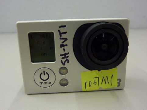
Click to zoom
Application Details
- Equipment Class
- DTS - Digital Transmission System
- Date of Grant
- Sep 20, 2012
- Application Purpose
- Original Equipment
- Date of Application
- Sep 18, 2012
- Equipment Note
- Digital HD Camera
- Frequency Range
- 2412.00000000 - 2462.00000000
- Company
- GoPro, Inc.
- Country
- United States
Documents & Files
Document Text
Text extracted from the exhibit documents filed with the FCC. Open a document above to read the original.
Users Manual
V 1 (MB) August 14 TITLE PAGE HERO3 White Edition | User Manual + Warranty Info PROMO PAGE Join the GoPro party at facebook.com/gopro to see what other GoPro owners are capturing. Share your footage and be a part of the GoPro excitement/movement! TABLE OF CONTENTS [CREATE ToC ONCE CONTENT FINAL] ACCESSORY PAGES [CREATE ONCE CONTENT FINAL] HERO3 FEATURES (order L to R, top to bottom) 1. LED Indicator Lights (Red 1 ) 2. SHUTTER/SELECT Button [S graphic] 3. LCD Status Screen 4. Wi-Fi Indicator Light (Blue 2 ) [W graphic] 5. HDMI Port (cable not included) 6. microSD Card Slot (card not included) 7. POWER/MODE Button [mode graphic] 8. HERO Port 9. USB Port (composite A/C cable/3.5mm stereo mic adapter/file transfer/charge/playback accessory connection) 10. Battery Door 11. Sound Indicator (located on camera bottom) 12. Wi-Fi ON/OFF CAMERA UPDATES Process TBD... Keep your camera updated with the latest features. Check gopro.com/update to download xxxxx. USING YOUR HERO3: BASICS GETTING STARTED Before using the HERO3 for first time: 1 Red flashes during capture; solid when charging 2 Blue flashes when connected to Wi-Fi 1. Insert a microSD, microSDHC or microSDXC card into the card slot. The narrowest part of card should enter slot first. (Class 4 or higher rated recommended) 2. Place battery into camera. 3. Charge the battery. The included lithium-ion battery comes partially charged. Connect included USB cable into camera; connect other end of cable to power source such as computer, GoPro wall or auto charger. While charging, the red Indicator Lights will be solid; when fully charged the red Indicator Lights will turn off. No damage will occur to camera or battery if used together prior to a full charge. > See STORAGE/MEMORY CARDS for more information. > See BATTERY LIFE for more information. CAMERA DEFAULT SETTINGS The HERO3 camera has been configured to start with the following default settings: [TABLE] [icon] Startup Mode Video 960p-30fps (NTSC) [icon] Photo Resolution 5 Megapixels (MP) [icon] Time Lapse Interval 0.5 second [icon] Burst Take up to 3 photos in 1 second [icon Wi-Fi Off [icon] Bluetooth Off OTHERS? PRO TIP! Want to customize how your camera captures photos and video? > See SETTINGS MENU to make changes. POWERING ON AND OFF To power ON: Press and release [mode]. The red LED Indicator Lights will flash three times and the Sound Indicator will emit three beeps. To power OFF: Press [mode] for two seconds, then release. The red LED Indicator Lights will flash several times and the Sound Indicator will emit seven beeps. Pro Tip: Need one-touch ON operation that starts video record immediately? Set camera to One Button mode. USING YOUR HERO3: MODES Overview The HERO3 features several camera operation modes. Each mode may be changed in the Settings menu. Press [mode] to cycle through in the following order: [TABLE] [icon] VIDEO Record video [icon] PHOTO Take single photo [icon] BURST Take up to 3 photos in 1 second 3 [icon] TIME LAPSE Take 1 photo every 0.5 seconds 4 [icon] SETTINGS Change camera settings [icon] PLAYBACK 5 View photos and videos on optional GoPro LCD BacPac, TV/HDTV (via optional HDMI, AV composite cable) Recording Video [video icon] Verify camera is in Video mode. If it is not showing, press [mode] repeatedly until it appears. The default video setting is 960p-30fps (NTSC). The LCD screen will display [video icon], FOV, video resolution setting, fps, number of videos stored on the memory card, balance of time remaining on card before the card is full and battery capacity. To start recording: Press and release [S]. The camera will emit one beep and the red LED Indicator Lights will flash while recording. To stop recording: Press and release [S]. The red LED Indicator Lights will flash three times and the camera will emit three beeps to indicate recording has stopped. The HERO3 automatically stops recording when memory card is full or battery is out of power. Video is saved before the camera powers OFF. PRO TIP: Activate One Button mode to have camera automatically begin recording video as soon as powered on. To halt recording and keep camera on, press and hold [S] for two seconds. To halt recording and turn camera off, press and hold [mode] for two seconds. >See One Button mode for more information. 3 Other settings include: take 3 photos in 1 second, 5 photos in 1 second, 10 photos in 2 seconds 4 Other settings include: take 1 photo every 1, 2, 5, 10, 30 or 60 seconds 5 Playback icon displayed only when GoPro LCD BacPac or other viewing device is connected TAKING PHOTOS [photo icon] Verify camera is in Photo mode. If it is not showing, press [mode] repeatedly until it appears. The default photo size is 5MP Wide. The LCD screen will display [mode], FOV, photo resolution size (MP), number of photos stored on the memory card, number of photos that can be taken before the card is full and battery capacity. To take a photo: Press and release [S]. The camera will beep one time and the red LED Indicator Lights will flash. ?ProTip! 11MP = x 8MP =x.... USING BURST MODE In Burst mode the camera will take multiple photos in a short period of time. The default setting is 3 photos in 1 second. [burst icon] Verify camera is in Burst mode. If it is not showing, press [mode] repeatedly until it appears. The LCD screen will display [mode], FOV, photo resolution size (MP), the Burst Mode setting, number of photos stored on the memory card, number of photos that can be taken before the card is full and battery capacity. To take Burst mode photo series: Press and release [S]. The red LED Indicator Lights will flash and the camera will beep 10 times. Pro Tip: Tracking fast action subjects and want to improve your chance for nailing a sharp shot? Set the camera to Burst and select the best from the series. MAKING TIME LAPSE PHOTO Time Lapse Photo mode captures a series of photos at 0.5, 1, 2, 5, 10, 30 or 60 second intervals (when using 0.5 seconds, it is recommended to use Class 10 or hi…
Text truncated - open the document above for the full version.
Users Manual
WARRANTY + DISCLAIMERS ENGLISH: Limited Warranty: GoPro warrants that for a period of one (1) year from original date of purchase the product will be free from defects in materials and workmanship under normal use. In the event of a defect, please contact GoPro Customer Support gopro.com/support for assistance. GoPro’s sole obligation under this warranty will be at its option to repair or replace the product. This warranty does not apply to products damaged by misuse, accident, or normal wear and tear. Because of possible user resealing error, this product is not warranted against water housing leakage or any resulting damage. ALL IMPLIED WARRANTIES OF MERCHANTABILITY OR FITNESS FOR A PARTICULAR PURPOSE ARE LIMITED TO THE DURATION OF THIS WARRANTY. GOPRO DISCLAIMS ALL OTHER EXPRESS OR IMPLIED WARRANTIES OR CONDITIONS. TO THE EXTENT NOT PROHIBITED BY LAW, IN NO EVENT WILL GOPRO BE LIABLE FOR ANY LOSS OF DATA, REVENUE OR PROFIT, OR FOR ANY SPECIAL, INDIRECT, CONSEQUENTIAL, INCIDENTAL OR PUNITIVE DAMAGES, HOWEVER CAUSED, ARISING OUT OF OR RELATED TO THE USE OF OR INABILITY TO USE THE PRODUCT, EVEN IF GOPRO HAS BEEN ADVISED OF THE POSSIBILITY OF SUCH DAMAGES. IN NO EVENT WILL GOPRO’S LIABILITY EXCEED THE AMOUNT PAID BY YOU FOR THE PRODUCT. Some jurisdictions do not allow limitations on how long an implied warranty lasts, or the exclusion or limitation of incidental or consequential damages, so the above limitations or exclusions may not apply to you. This warranty gives you specific legal rights, and you may also have other rights which vary by jurisdiction. IC Regulations: This device complies with Industry Canada license-exempt RSS standards. Operation is subject to the following two conditions: (1) this device may not cause interference and; (2) this device must accept any interference--including interference that may cause undesired operation of the device. This Class B digital apparatus complies with Canadian ICES-003. The County Code Selection feature is disabled for products marketed in the US/Canada. For product available in the USA/ Canada markets, only channel 1~11 can be operated. Selection of other channels is not possible. IMPORTANT NOTE: IC Radiation Exposure Statement This EUT is compliance with SAR for general population/uncontrolled exposure limits in IC RSS-102 and had been tested in accordance with the measurement methods and procedures specified in IEEE 1528. The symbol above means that according to local laws and regulations your product should be disposed of separately from household waste. When this product reaches its end of life, take it to a collection point designated by local authorities. Some collection points accept products for free. The separate collection and recycling of your product at the time of disposal will help conserve natural resources and ensure that it is recycled in a manner that protects human health and the environment. FCC STATEMENT Warning: Changes or modifications to this unit not expressly approved by the party responsible for compliance could void the user’s authority to operate the equipment. NOTE: This equipment has been tested and found to comply with the limits for Class B digital device, pursuant to part 15 of the FCC Rules. These limits are designed to provide reasonable protection against harmful interference in a residential installation. This equipment generates and can radiate radio frequency energy and, if not installed and used in accordance with the instructions, may cause harmful interference to radio communications. However, there is no guarantee that interference will not occur in a particular installation. If this equipment does cause harmful interference to radio or television reception, which can be determined by turning the equipment off and on, the user is encouraged to try to correct the interference by one or more of the following measures: • Reorient or relocate the receiving antenna. • Increase the separation between the equipment and the receiver. • Connect the equipment into an outlet on a circuit different from that to which the receiver is connected. • Consult the dealer or an experienced radio/TV technician for help. This device complies with Part 15 of the FCC Rules. Operation is subject to the following two conditions: (1) This device may not cause harmful interference and; (2) This device must accept any interference received, including interference that may cause undesired operation. RF Exposure Information (SAR) This device meets the government’s requirements for exposure to radio waves. This device is designed and manufactured not to exceed the emission limits for exposure to radio frequency (RF) energy set by the Federal Communications Commission of the U.S. Government and Industry Canada of the Canadian Government. The exposure standard employs a unit of measurement known as the Specific Absorption Rate, or SAR. The SAR limit set by the FCC and IC is 1.6W/kg. Tests for SAR are conducted using standard operating positions accepted by the FCC and IC, with the EUT transmitting at the specified power level in different channels. The highest SAR value for the device as reported to the FCC and IC is 1.26 W/kg (body), 1.496 W/kg (head), for CHDHE-301; 1.23 W/kg (body) for CHDHN-301. The FCC and IC have granted an Equipment Authorization for this device with all reported SAR levels evaluated as in compliance with the FCC and IC RF exposure guidelines. SAR information on this device is on file with the FCC and IC, and can be found under the Display Grant section of www.fcc.gov/oet/ea/fccid after searching on FCC ID: CNFCHDHE301, CNFCHDHN301. This device is compliance with SAR for general population /uncontrolled exposure limits in ANSI/IEEE C95.1-1999 and had been tested in accordance with the measurement methods and procedures specified in OET Bulletin 65 Supplement C. DECLARATION OF CONFORMITY GoPro, 3000 Clearview Way, San Mateo, CA 94402 USA Declares under our sole responsibility that the product: Product Na…
Text truncated - open the document above for the full version.
Users Manual
1 Materials including information and pictures presen ted in this document are confidential and intended solely for the person or organization to whom it is presented. It may contain privileged and confidential information. I f you are not the intended audience or recipient, yo u should not copy, distribute or take any action in reliance on it. All rights, including information and pictures pres ented in this presentation are sole properties of AmphenolTaiwan Corporation www.amphenol-saa.com Connecting people with technology HD3 Antenna Design Amphenol 2012/08/03 2 Materials including information and pictures presen ted in this document are confidential and intended solely for the person or organization to whom it is presented. It may contain privileged and confidential information. I f you are not the intended audience or recipient, yo u should not copy, distribute or take any action in reliance on it. All rights, including information and pictures pres ented in this presentation are sole properties of AmphenolTaiwan Corporation www.amphenol-saa.com Connecting people with technology Revision History NA 2011/10/14 First dummy evaluation A NA 2011/10/21 WIFI module in battery side with cable connect to antenna evaluation B NA 2011/10/24 Front Cover is all metal C NA 2011/10/25 Different WIFI module position at front metal cover fixture D NA 2011/10/26 Front metal cover comparison E NA 2011/10/27 With/ without metal column of lens F NA 2011/10/28 Radiation pattern evaluation G NA 2011/11/03 11/2 3D drawing antenna evaluation H NA 2011/11/08 11/7 3D drawing antenna evaluation I NA 2011/11/10 Increase PCB area evaluation J NA 2011/11/11 11/7 3D drawing improve antenna radiation pattern and efficiency evaluation K 2011/11/18 Date NA Use real battery to evaluate L Drawing NO. Destitution Revision 3 Materials including information and pictures presen ted in this document are confidential and intended solely for the person or organization to whom it is presented. It may contain privileged and confidential information. I f you are not the intended audience or recipient, yo u should not copy, distribute or take any action in reliance on it. All rights, including information and pictures pres ented in this presentation are sole properties of AmphenolTaiwan Corporation www.amphenol-saa.com Connecting people with technology Revision History NA 2012/02/15 With/without water housing antenna performance V NA 2012/02/10 Modify EVT unit to check antenna performance U NA 2011/11/22 Add PCB area close to the feed point in main board M NA 2012/01/20 Base on 1/17 mockup to evaluate N NA 2012/02/03 Evaluate antenna base on EVT 1 device O NA 2012/02/03 Evaluate antenna base on Chicony support grounding position P NA 2012/02/04 Find grounding position to increase antenna performance-1 Q NA 2012/02/06 Find grounding position to increase antenna performance-2 R NA 2012/02/07 Battery without connect metal plate and real board antenna evaluation S NA 2012/02/10 Used TCL and BYD battery to evaluate antenna T Date Drawing NO. Destitution Revision 4 Materials including information and pictures presen ted in this document are confidential and intended solely for the person or organization to whom it is presented. It may contain privileged and confidential information. I f you are not the intended audience or recipient, yo u should not copy, distribute or take any action in reliance on it. All rights, including information and pictures pres ented in this presentation are sole properties of AmphenolTaiwan Corporation www.amphenol-saa.com Connecting people with technology Revision History CY5324-12-001-C-FA00 2012/06/04 Base on 4/25 EVT3 device with water housing Y CY5324-12-001-C-FA00 2012/06/04 Base on 4/25 EVT3 device to evaluate antenna X 2012/08/032012/07/042012/03/09 Date CY5324-12-001-C-FA00 Base on DVT1 unit to evaluate antenna Z C-5324-12-001-C-TB00 Base on 3/9 EVT2 device to evaluate antenna W CY5324-12-001-C-FB00 Base on PVT1 unit to measure the antenna performance AA Drawing NO. Destitution Revision 5 Materials including information and pictures presen ted in this document are confidential and intended solely for the person or organization to whom it is presented. It may contain privileged and confidential information. I f you are not the intended audience or recipient, yo u should not copy, distribute or take any action in reliance on it. All rights, including information and pictures pres ented in this presentation are sole properties of AmphenolTaiwan Corporation www.amphenol-saa.com Connecting people with technology Outline • Test equipment introduction• Antenna Placement• Antenna Performance• Conclusions 6 Materials including information and pictures presen ted in this document are confidential and intended solely for the person or organization to whom it is presented. It may contain privileged and confidential information. I f you are not the intended audience or recipient, yo u should not copy, distribute or take any action in reliance on it. All rights, including information and pictures pres ented in this presentation are sole properties of AmphenolTaiwan Corporation www.amphenol-saa.com Connecting people with technology Test equipment introduction 7 Materials including information and pictures presen ted in this document are confidential and intended solely for the person or organization to whom it is presented. It may contain privileged and confidential information. I f you are not the intended audience or recipient, yo u should not copy, distribute or take any action in reliance on it. All rights, including information and pictures pres ented in this presentation are sole properties of AmphenolTaiwan Corporation www.amphenol-saa.com Connecting people with technology Configuration of Satimo Stargate 64 8 Materials including information and pictures presen ted in this document are confidential and intended solely for the person or organization to whom it is presented. It may contain privileged and con…
Text truncated - open the document above for the full version.
External Photos
External Photos FCC ID: CNFCHDHE301 IC: 10193A-CHDHE301 Front View Back View Top View Left side View Right side View
ID Label/Location Info
0.18 0.18 31+/ - 0.1 5mm 5mm 7mm 09/05/2012 1 27+/-0.1 BK70% GoPro N136 HERO3 White Edition: Model: CHDHE-301 FCC ID: CNFCHDHE301 MODEL: CHDHE-301 5V ,1A 2 FCC ID: CNFCHDHE301 IC: 10193A-CHDHE301 MADE IN CHINA IC: 10193A-CHDHE301 Scale: 1/1 3 R=0.2 Scale: 1/1 N136 Label Position: 0.18 0.18 25# Silver Label + UV Coating 2. Total thickness: 0.05mm +/-0.01 4 3. Printing Color: BK100+BK70% 4. Size: 31 x 27mm (R=0.2 x4) 5. Unit: mm N136 GoPro MODEL: CHDHE-301 5V ,1A FCC ID: CNFCHDHE301 IC: 10193A-CHDHE301 MADE IN CHINA 2012-08-03 2012-08-03 N/A SFTY LBL HERO3 WHITE EDITION 445-01905-000
Internal Photos
Internal Photos FCC ID: CNFCHDHE301 IC: 10193A-CHDHE301 Front cover Removed Front cover Front cover and display Removed Enclosure Antenna Antenna Bottom Side Antenna Bottom top side Main Board Back side with Camera unit Camera unit and inner side of Sensor Board Exposed Camera unit and Sensor Board removed from main board IO PCB Back IO PCB Front side Sensor PCB Front Sensor PCB Backside showing Heat sink Main Board Back side LCD Flex Front side LCD Flex Back side
RF Exposure Info
© 2012 RF Exposure Lab, LLC This report shall not be reproduced except in full without the written approval of RF Exposure Lab, LLC. 802 N. Twin Oaks Valley Road, Suite 105 • San Marcos, CA 92069 • U.S.A. TEL (760) 471-2100 • FAX (760) 471-2121 http://www.rfexposurelab.com CERTIFICATE OF COMPLIANCE SAR EVALUATION GoPro Dates of Test: August 10, 2012 3000 Clearview Way Test Report Number: SAR.20120801 San Mateo, CA 94402 This wireless mobile and/or portable device has been shown to be compliant for localized specific absorption rate (SAR) for uncontrolled environment/general exposure limits specified in ANSI/IEEE Std. C95.1-1992 and had been tested in accordance with the measurement procedures specified in IEEE 1528-2003, and OET Bulletin 65 Supp. C (See test report). I attest to the accuracy of the data. All measurements were performed by myself or were made under my supervision and are correct to the best of my knowledge and belief. I assume full responsibility for the completeness of these measurements and vouch for the qualifications of all persons taking them. RF Exposure Lab, LLC certifies that no party to this application is subject to a denial of Federal benefits that includes FCC benefits pursuant to Section 5301 of the Anti-Drug Abuse Act of 1988, 21 U.S.C. 853(a). Jay M. Moulton Vice President Certificate # 2387.01 FCC ID: CNFCHDHE301 IC Certificate: 10193A-CHDHE301 Model(s): CHDHE-301 Test Sample: Engineering Unit Same as Production Serial Number: 649 Equipment Type: Wireless Camera Classification: Portable Transmitter Next to Face and Body TX Frequency Range: 2412 – 2462 MHz Frequency Tolerance: ± 2.5 ppm Maximum RF Output: 2450 MHz (b) – 16 dB, 2450 MHz (g) – 16 dB Conducted Signal Modulation: DSSS, OFDM Antenna Type: Internal Application Type: Certification FCC Rule Parts: Part 2, 15C KDB Test Methodology: KDB 447498, KDB 248227 Industry Canada: RSS-102, Safety Code 6 Maximum Head SAR Value: 1.496 W/kg Maximum Body SAR Value: 1.260 W/kg Separation Distance: 0 mm FCC ID: CNFCHDHE301 © 2012 RF Exposure Lab, LLC Page 2 of 106 This report shall not be reproduced except in full without the written approval of RF Exposure Lab, LLC. Table of Contents 1. Introduction ........................................................................................................................... 3 SAR Definition [5] ...................................................................................................................... 3 2. SAR Measurement Setup ..................................................................................................... 4 Robotic System ......................................................................................................................... 4 System Hardware ..................................................................................................................... 4 System Description ................................................................................................................... 4 E-Field Probe ............................................................................................................................ 5 3. Robot Specifications ............................................................................................................. 7 4. Probe and Dipole Calibration ................................................................................................ 8 5. Phantom & Simulating Tissue Specifications ........................................................................ 9 SAM Phantom ........................................................................................................................... 9 Head & Body Simulating Mixture Characterization ................................................................... 9 Device Holder ........................................................................................................................... 9 6. ANSI/IEEE C95.1 – 1992 RF Exposure Limits [2] ............................................................... 10 Uncontrolled Environment ....................................................................................................... 10 Controlled Environment .......................................................................................................... 10 7. Measurement Uncertainty ................................................................................................... 11 8. System Validation ............................................................................................................... 12 Tissue Verification ................................................................................................................... 12 Test System Verification ......................................................................................................... 12 9. SAR Test Data Summary .................................................................................................... 13 Procedures Used To Establish Test Signal ............................................................................. 13 Device Test Condition ............................................................................................................. 13 Test LocationsSAR Data Summary – 2450 MHz Head 802.11b ............................................ 14 SAR Data Summary – 2450 MHz Head 802.11b .................................................................... 15 SAR Data Summary – 2450 MHz Body 802.11b .................................................................... 16 10. Test Equipment List ........................................................................................................ 17 11. Conclusion ...................................................................................................................... 18 12. References ...................................................................................................................... 19 Appendix A – Sy…
Text truncated - open the document above for the full version.
Test Report
Report Number: 31262682.001 Page 1 of 109 EUT: HERO3 White Edition Model: CHDHE-301 EMC / Rev 9/13/2012 FCCID: CNFCHDHE301 IC: 10193A-CHDHE301 Emissions Test Report EUT Name: HERO3 White Edition Model No.: CHDHE-301 CFR 47 Part 15.247 2011 and RSS 210: 2010 Prepared for: Steven Kim Woodman Labs, Inc (dba GoPro) 3000 Clearview Way San Mateo, CA 94402 Tel: 650-332-7600 Prepared by: TUV Rheinland of North America, Inc. 1279 Quarry Lane Pleasanton, CA 94566 Tel: (925) 249-9123 Fax: (925) 249-9124 http://www.tuv.com/ Report/Issue Date: September 13, 2012 Report Number: 31262682.001 Statement of Compliance Report Number: 31262682.001 Page 2 of 109 EUT: HERO3 White Edition Model: CHDHE-301 EMC / Rev 9/13/2012 FCCID: CNFCHDHE301 IC: 10193A-CHDHE301 Manufacturer: Woodman Labs, Inc (dba GoPro). 3000 Clearview Way San Mateo, CA 94402 U.S.A. Requester / Applicant: Steven Kim Name of Equipment: HERO3 White Edition Model No. CHDHE-301 Type of Equipment: Intentional Radiator Application of Regulations: CFR 47 Part 15.247 2011 and RSS 210: 2010 Test Dates: August 23 – September 11, 2012 Guidance Documents: Emissions: ANSI C63.10-2009. Test Methods: Emissions: ANSI C63.10-2009. The electromagnetic compatibility test and documented data described in this report has been performed and recorded by TUV Rheinland, in accordance with the standards and procedures listed herein. As the responsible authorized agent of the EMC laboratory, I hereby declare that the equipment described above has been shown to be compliant with the EMC requirements of the stated regulations and standards based on these results. If any special accessories and/or modifications were required for compliance, they are listed in the Executive Summary of this report. This report must not be used to claim product endorsement by A2LA. This report contains data that are not covered by A2LA accreditation. This report shall not be reproduced except in full, without the written authorization of TUV Rheinland of North America. Suresh Kondapalli September 14, 2012 Conan Boyle September 14, 2012 Test Engineer Date A2LA Signatory Date INDUSTRY CANADA Testing Cert #3331.03 US5254 2932M-1 Index of Tables Report Number: 31262682.001 Page 3 of 109 EUT: HERO3 White Edition Model: CHDHE-301 EMC / Rev 6/21/2012 FCCID: CNFCHDHE301 IC: 10193A-CHDHE301 1 Executive Summary _______________________________________________________ 6 1.1 Scope______________________________________________________________________ 6 1.2 Purpose____________________________________________________________________ 6 1.3 Summary of Test Results _____________________________________________________ 6 1.3.1 Measured values of key parameters ____________________________________________________ 7 1.4 Special Accessories __________________________________________________________ 7 1.5 Equipment Modifications _____________________________________________________ 7 2 Laboratory Information ____________________________________________________ 8 2.1 Accreditations & Endorsements _______________________________________________ 8 2.1.1 US Federal Communications Commission _______________________________________________ 8 2.1.2 A2LA ___________________________________________________________________________ 8 2.1.3 Canada – Industry Canada ___________________________________________________________ 8 2.1.4 Japan – VCCI _____________________________________________________________________ 8 2.1.5 Acceptance by Mutual Recognition Arrangement _________________________________________ 8 2.2 Test Facilities _______________________________________________________________ 9 2.2.1 Emission Test Facility ______________________________________________________________ 9 2.2.2 Immunity Test Facility ______________________________________________________________ 9 2.3 Measurement Uncertainty ____________________________________________________ 9 2.3.1 Sample Calculation – radiated & conducted emissions ____________________________________ 10 2.3.2 Measurement Uncertainty ___________________________________________________________ 10 2.4 Calibration Traceability _____________________________________________________ 11 3 Product Information ______________________________________________________ 12 3.1 Product Description ________________________________________________________ 12 3.2 Equipment Configuration ___________________________________________________ 12 3.3 Operating Mode ___________________________________________________________ 12 3.4 Duty Cycle: _______________________________________________________________ 12 3.5 Unique Antenna Connector __________________________________________________ 13 3.5.1 Results _________________________________________________________________________ 13 4 Emission Requirements – 2400 MHz to 2483.5 MHz Band __________________…
Text truncated - open the document above for the full version.
Contact Information
Applicant
Michelle Tsai(Director of Product Safety and Compliance)
Test Firm
TUV Rheinland of North America Inc.David Spencer
Technical Specifications
| # | Rule Parts | Frequency Range | Power Output |
|---|---|---|---|
| 1 | 15C | 2.41 GHz - 2.46 GHz | 107.00 mW |
Other Applications from GoPro, Inc.
CNFACVT2
Apr 09, 2026BATTERY GRIP/TRIPOD/REMOTE
Equipment Class
DTS - Digital Transmission SystemCNFCPSS1
Aug 28, 2024Camera with Bluetooth and Wi-Fi
Equipment Class
NII - Unlicensed National Information Infrastructure TXCNFAMFR1
Mar 25, 2024Camera
Equipment Class
DTS - Digital Transmission System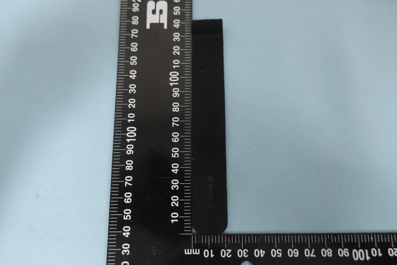
CNFACCH1
Aug 31, 2023Remote Control
Equipment Class
DTS - Digital Transmission System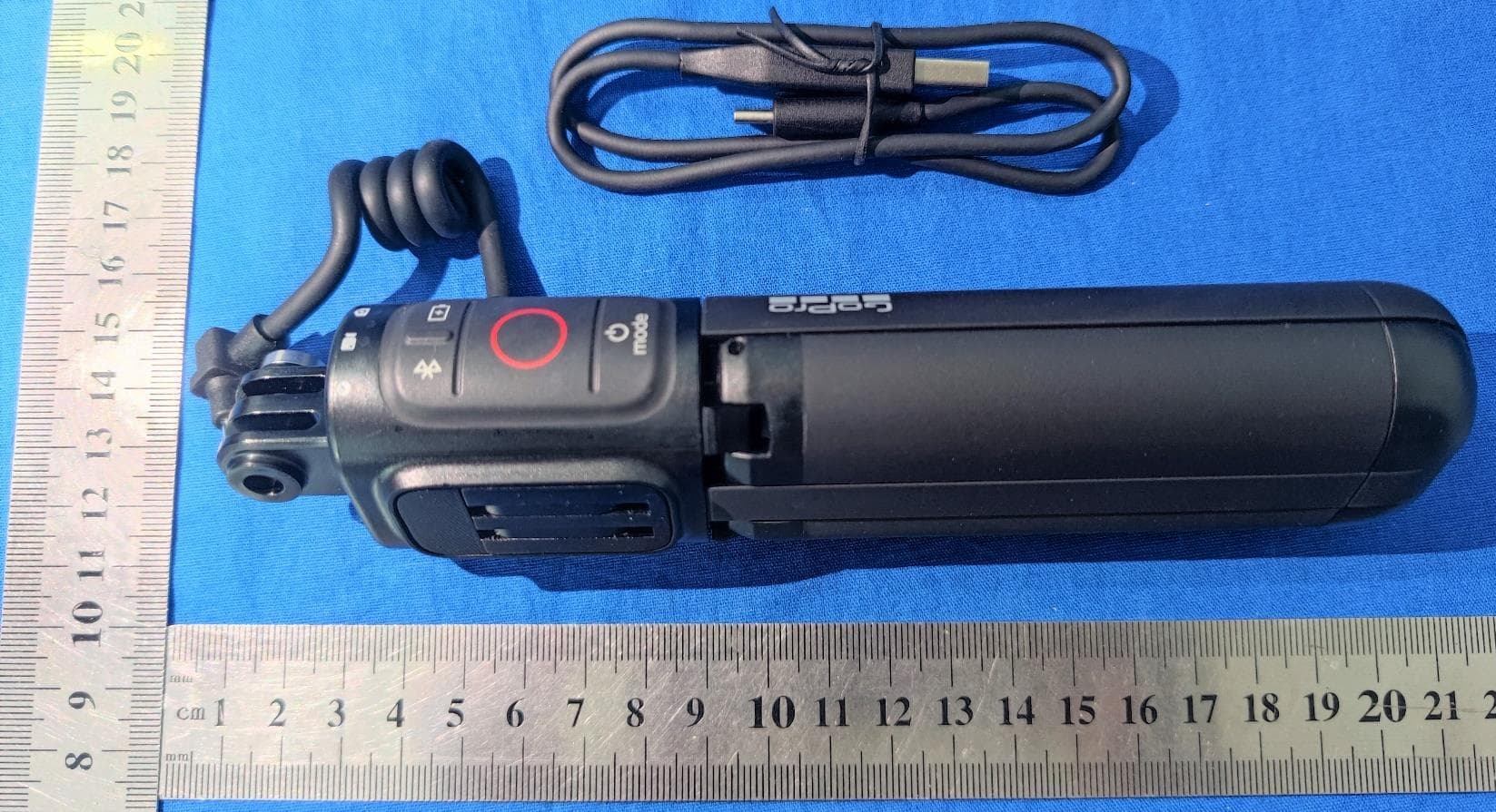
CNFACVT1
Aug 09, 2021Grip supports Bluetooth Low Energy
Equipment Class
DTS - Digital Transmission System