CNFHWPP1Camera
GoPro, Inc.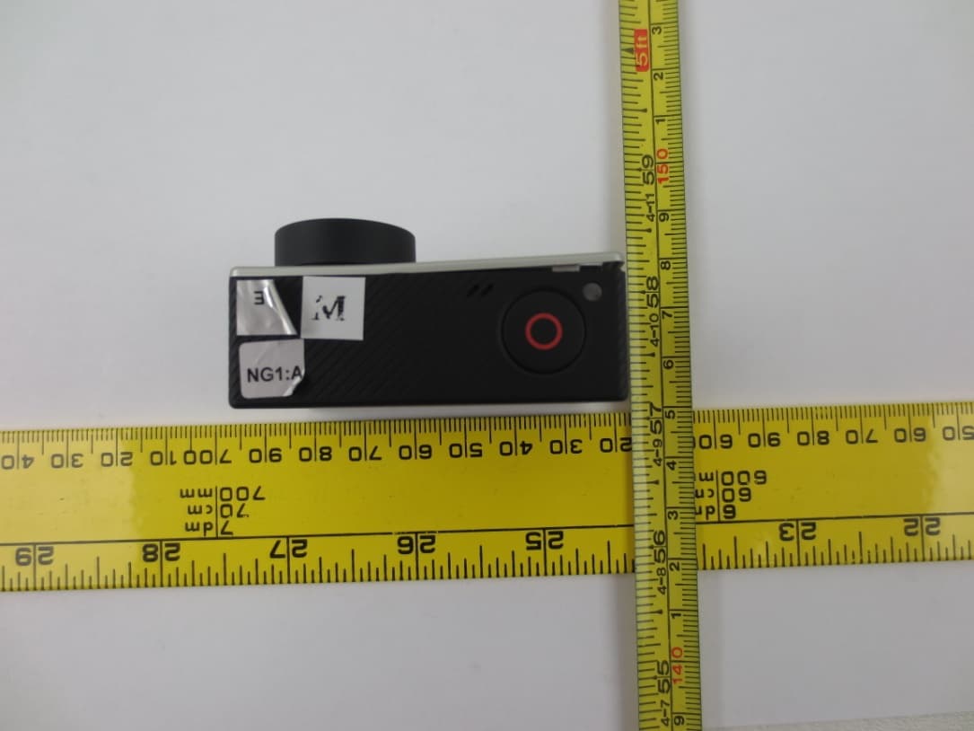
Click to zoom
Application Details
- Equipment Class
- DTS - Digital Transmission System
- Date of Grant
- Sep 09, 2014
- Application Purpose
- Original Equipment
- Date of Application
- Sep 09, 2014
- Equipment Note
- Camera
- Frequency Range
- 2412.00000000 - 2462.00000000
- Company
- GoPro, Inc.
- Country
- United States
Documents & Files
Document Text
Text extracted from the exhibit documents filed with the FCC. Open a document above to read the original.
Users Manual
USER MANUAL 2 twitter.com/GoPro youtube.com/GoProfacebook.com/GoPro instagram.com/GoPro / Join the GoPro Movement 3 To download this user manual in a different language, visit gopro.com/support. Pour télécharger ce manuel de l’utilisateur dans une autre langue, rendez-vous sur gopro.com/support. Wenn Sie dieses Benutzerhandbuch in einer anderen Sprache herunterladen möchten, besuchen Sie gopro.com/support. P er scaricare questo manuale utente in un’altra lingua, visita g opro.com/support. P ara descargar este manual de usuario en otro idioma, visite g opro.com/support. P ara baixar este manual do usuário em outro idioma, acesse gopro.com/support. このユーザーマニュアルの他言語版をダウンロードするに は、 g opro.com/supportにアクセスしてください。 若要下載其他語言版本的使用說明書,請前往: gopro.com/support。 如需下载本用户手册的其他语言版本,请访问 gopro.com/support。 4 Optional Accessories6 The Basics8 Getting Started10 Camera Status Screen15 Camera Icons16 Camera Menus18 Camera Modes20 Navigating Settings Menus21 Video Mode22 Photo Mode36 Multi-Shot Mode40 Playback Mode47 Setup Mode50 Connecting to the GoPro App58 Transferring Files to a Computer59 Protune ™ 60 Battery66 Important Messages72 Camera Housing74 / Table of Contents 5 / Table of Contents Using the Mounts79 Frequently Asked Questions82 Customer Support84 Trademarks84 Regulatory Information84 6 Battery BacPac ™ LCD Touch BacPac ™ Smart RemoteChesty (Chest Harness) The FrameJaws: Flex Clamp Dual Battery Charger for HERO4 Batteries 3-Way / Optional Accessories 7 Suction CupHead Strap + QuickClip Surfboard MountsTripod Mounts Roll Bar MountFetch (Dog Harness) See more at gopro.com. Floaty Backdoor / Wear It. Mount It. Love It. ™ 8 1. Camera Status Light (red) 2. Shutter/Select Button [ ] 3. Wireless Status Light (blue) 4. Camera Status Screen 5. P ower/Mode Button [ ] 6. Micro HDMI Port (cable not included) 7. mi croSD Card Slot (microSD card not included) 8. Mini-USB Port (supports composite A/C cable/3.5mm stereo mic adapter, not included) 9. Audio Alert / The Basics 9 10. Microphone 11. HERO Port 12. Settings/Tag Button [ ] 13. Battery Door / The Basics 10 / Getting Started CHARGING THE BATTERY 1. R emove the camera from its housing. 2. Remove the camera side door and insert a microSD, microSDHC or microSDXC card (sold separately) into the card slot. A microSD card with a Class 10 or UHS-1 rating is required. 3. O pen the bottom door, insert the battery and then close the b ot to m d o o r. Slim housing surfboard mount installation Slim housing remove camera Slim housing insert camera Slim housing closedSwapping housing doors Quick Release Buckle + Thumb Screw + Slim housing = Complete Unit 11 / Getting Started 4. Charge the battery by connecting the camera to a computer using the included USB cable. The charging icon appears on the camera status screen and shows a full battery when charging is complete. The included lithium-ion battery comes partially charged. No damage occurs to the camera or battery if used prior to a full charge. PRO TIP: With the Dual Battery Charger, you can charge your battery outside of the camera. For details, visit gopro.com. For more battery information, see Battery. WARNING: Use caution when using your GoPro as part of your active lifestyle. Always be aware of your surroundings to avoid injury to yourself and others. Abide by all local laws when using this camera. 12 CAMERA SOFTWARE UPDATES To get the latest features and best performance from your HERO4 camera, make sure you are using the most current camera software. You can update your camera software via the GoPro App, GoPro software or at gopro.com/getstarted. CAMERA DEFAULT SETTINGS The HERO4 Black camera powers up with the following default settings: Video1080p30 SuperView Photo12MP, Wide Field of View (FOV) Multi-ShotBurst option (set to 30 photos in 1 second) QuikCaptureOff WirelessOff To change your Video or Photo settings, see Video Settings and Photo Settings. / Getting Started 13 POWERING ON + OFF To Power On: Press the Power/Mode button [ ] once. The camera status lights (red) flash three times and the sound indicator emits three beeps. When the camera status screen displays information, your camera is on. To Power Off: Press and hold the Power/Mode b utton [ ] for two seconds. The camera status lights (red) flash several times and the sound indicator emits seven beeps. PRO TIP: When the camera is off and QuikCapture is enabled, you can turn the camera on and immediately begin capturing video or Time Lapse photos just by pressing the Shutter/Select button [ ]. Press once for video, press and hold for two seconds for Time Lapse photos. Press again to stop recording and power off the camera. For details, see QuikCapture in Setup Mode. / Getting Started 14 INSERTING + REMOVING MICROSD CARDS The HERO4 Black camera is compatible with 4GB, 8GB, 16GB, 32GB and 64GB capacity microSD, microSDHC and microSDXC memory cards ( sold separately). You must use a microSD card with a Class 10 or a UHS-1 rating. GoPro recommends using brand name memory cards for m aximum reliability in high-vibration activities. To Insert the microSD Card:To Remove the microSD Card: Slide the memory card into the card slot with the label facing the front of the camera. When fully inserted, the card clicks into place. Place your fingernail against the edge of the memory card and lightly press it further into the camera. The card springs out far enough to be removed. NOTICE: Use care when handling memory cards. Avoid liquids, dust and debris. As a precaution, power off the camera before inserting or removing the card. Check manufacturer guidelines regarding use in acceptable temperature ranges. / Getting Started 15 Your HERO4 Black features a status screen that displays the following information about modes and settings : 1. Camera Modes/FOV (field of view) 2. C amera Settings 3. Resolution/fps (frames per second) 4. P rotune 5. Number of Files Captured 6. Time/Storage/Files 7. Wireless 8. B attery Life Note: The icons that appear on the camera status sc…
Text truncated - open the document above for the full version.
Cover Letter(s)
3000 Clearview Way, San Mateo, CA 94402 415.738.2480 www.gopro.com FCC Confidential Authorization 8/4/2013 FEDERAL COMMUNICATIONS COMMISSIONS Authorization and Evaluation Division 7435 Oakland Mills Road Columbia, MD 21046 Subject: Confidentiality Request regarding application for certification of FCC ID: CNFHWPP1 In accordance with Sections 0.457 and 0.459 of the Commission’s Rules, GoPro Inc., hereby requests long-term confidential treatment of information accompanying this application as outlined below: Block Diagram Schematics Operation Description As well as short-term confidential treatment of information accompanying this application as outlined below: Internal Photos User’s Manual External Photos Test Set-up Photos The above materials contain proprietary and confidential information not customarily released to the public. The public disclosure of these materials provides unjustified benefits to its competitors in the market. Sincerely, John Wyatt, / Director QA [email protected]
External Photos
GoPro, Inc. FCC ID: CNFHWPP1; IC: 10193A-HWPP1 Report Number: R1406136-247 Page 70 of 77 FCC Part 15C/IC RSS-210 Test Report 15 Exhibit C – EUT Photographs 15.1 EUT- Front View 15.2 EUT- Right Side View GoPro, Inc. FCC ID: CNFHWPP1; IC: 10193A-HWPP1 Report Number: R1406136-247 Page 71 of 77 FCC Part 15C/IC RSS-210 Test Report 15.3 EUT- Rear View 15.4 EUT- Left Side View GoPro, Inc. FCC ID: CNFHWPP1; IC: 10193A-HWPP1 Report Number: R1406136-247 Page 72 of 77 FCC Part 15C/IC RSS-210 Test Report 15.5 EUT- Top Side View 15.6 EUT- Bottom Side View
ID Label/Location Info
A-LABEL A-LABEL 4 3 1 2 3 1 4 D C A B A B C D 2 5 5 SHEET 2 OF 2 SIZE DRAWING NUM REV PART DESCRIPTION 1.06 0.55 LABEL, REGULATORY, UNIBODY, HERO4, BLACK EDITION B446-07098-0001 DO NOT SCALE DRAWING THIS ENGINEERING DRAWING AND SPECIFICATION CONTAINS CONFIDENTIAL, TRADE SECRET, AND OTHER PROPRIETARY INFORMATION OF GoPro. THIS DOCUMENT MAY NOT BE TRANSFERRED OR COPIED WITHOUT THE EXPRESS WRITTEN AUTHORIZATION OF GoPro. IN ADDITION, NEITHER THIS SHEET NOR THE INFORMATION IT CONTAINS MAY BE USED BY OR DISCLOSED TO ANY THIRD PARTY WITHOUT GoPro's EXPRESS WRITTEN CONSENT. SEE DETAIL A SEE DETAIL B BATTERY COMPARTMENT SECTION A-A DETAIL A SCALE 6.000 LABEL BATTERY COMPARTMENT DETAIL B SCALE 6.000 LABEL BATTERY COMPARTMENT LABEL
Internal Photos
GoPro, Inc. FCC ID: CNFHWPP1; IC: 10193A-HWPP1 Report Number: R1406136-247 Page 73 of 77 FCC Part 15C/IC RSS-210 Test Report 15.7 EUT- EUT open Case View 1 15.8 EUT- EUT open Case View 2 GoPro, Inc. FCC ID: CNFHWPP1; IC: 10193A-HWPP1 Report Number: R1406136-247 Page 74 of 77 FCC Part 15C/IC RSS-210 Test Report 15.9 EUT- PCB Board Top View 15.10 EUT- PCB Board Bottom View Antenna GoPro, Inc. FCC ID: CNFHWPP1; IC: 10193A-HWPP1 Report Number: R1406136-247 Page 75 of 77 FCC Part 15C/IC RSS-210 Test Report 15.11 EUT- Camera Board Top View 15.12 EUT- Camera Board Bottom View GoPro, Inc. FCC ID: CNFHWPP1; IC: 10193A-HWPP1 Report Number: R1406136-247 Page 76 of 77 FCC Part 15C/IC RSS-210 Test Report 15.13 EUT- SD Card Board Top View 15.14 EUT- SD Card Board Rear View --- END OF REPORT --- _ GoPro, Inc. FCC ID: CNFHWPP1; IC: 10193A-HWPP1 Report Number: R1406136-247 Page 77 of 77 FCC Part 15C/IC RSS-210 Test Report 15.15 EUT- EUT Lens View 15.16 EUT- LI-ION Battery View --- END OF REPORT ---
Test Report
Note: This test report is prepared for the customer shown above and for the device described herein. It may not be duplicated or used in part without prior written consent from Bay Area Compliance Laboratories Corp. This report must not be used by the customer to claim product certification, approval, or endorsement by A2LA*, NIST, or any agency of the Federal Government. * This report may contain data that are not covered by the A2LA accreditation and are marked with an asterisk “*” (Rev.2) FCC PART 15, SUBPART C IC RSS-210, ISSUE 8, DECEMBER 2010 TEST AND MEASUREMENT REPORT For GoPro, Inc. 3000 Clearview Way, San Mateo, CA 94402, USA FCC ID: CNFHWPP1 IC: 10193A-HWPP1 Report Type: Original Report Product Type: Portable Camera with 2.4 GHz WLAN and BLE Prepared By Cipher Chu Test Engineer Report Number R1406136-247 Report Date 2014-08-29 Reviewed By Ivan Cao RF Lead Bay Area Compliance Laboratories Corp. 1274 Anvilwood Avenue, Sunnyvale, CA 94089, USA Tel: (408) 732-9162 Fax: (408) 732-9164 GoPro, Inc. FCC ID: CNFHWPP1; IC: 10193A-HWPP1 Report Number: R1406136-247 Page 2 of 77 FCC Part 15C/IC RSS-210 Test Report TABLE OF CONTENTS 1 General Description ..................................................................................................................................................... 5 1.1 Product Description for Equipment Under Test (EUT) ...................................................................................... 5 1.2 Mechanical Description of EUT ......................................................................................................................... 5 1.3 Objective ............................................................................................................................................................. 5 1.4 Related Submittal(s)/Grant(s) ............................................................................................................................. 5 1.5 Test Methodology ............................................................................................................................................... 5 1.6 Measurement Uncertainty ................................................................................................................................... 5 1.7 Test Facility ........................................................................................................................................................ 6 2 System Test Configuration.......................................................................................................................................... 7 2.1 Justification ......................................................................................................................................................... 7 2.2 EUT Exercise Software....................................................................................................................................... 7 2.3 Equipment Modifications.................................................................................................................................... 7 2.4 Local Support Equipment ................................................................................................................................... 7 2.5 EUT Internal Configuration Details .................................................................................................................... 7 2.6 Power Supply and Line Filters ............................................................................................................................ 7 2.7 Interface Ports and Cabling ................................................................................................................................. 8 3 Summary of Test Results ............................................................................................................................................ 9 4 FCC §15.247(i), §2.1093 & IC RSS-102 – RF Exposure ........................................................................................... 10 4.1 Applicable Standards ........................................................................................................................................ 10 4.2 Test Result ........................................................................................................................................................ 10 5 FCC §15.203 & IC RSS-Gen §7.1.2 – Antenna Requirements ................................................................................ 11 5.1 Applicable Standards ........................................................................................................................................ 11 5.2 Antenna Description ......................................................................................................................................... 11 6 FCC §15.207 & IC RSS-Gen §7.2.4 – AC Line Conducted Emissions .................................................................... 12 6.1 Applicable Standards ........................................................................................................................................ 12 6.2 Test Setup ......................................................................................................................................................... 12 6.3 Test Procedure .................................................................................................................................................. 12 6.4 Corrected Amplitude & Margin Calculation ..................................................................................................... 13 6.5 Test Setup Block Diagram ................................................................................................................................ 13 6.6 Test Equipment List and Details ................................................................................................................…
Text truncated - open the document above for the full version.
Test Setup Photos
GoPro, Inc. FCC ID: CNFHWPP1; IC: 10193A-HWPP1 Report Number: R1406136-247 Page 67 of 77 FCC Part 15C/IC RSS-210 Test Report 14 Exhibit B – Test Setup Photographs 14.1 Radiated Emission below 1 GHz Front View at 3 Meters 14.2 Radiated Emission below 1 GHz Rear View at 3 Meters GoPro, Inc. FCC ID: CNFHWPP1; IC: 10193A-HWPP1 Report Number: R1406136-247 Page 68 of 77 FCC Part 15C/IC RSS-210 Test Report 14.3 Radiated Emission above 1 GHz Front View at 3 Meters 14.4 Radiated Emission above 1 GHz Rear View at 3 Meters GoPro, Inc. FCC ID: CNFHWPP1; IC: 10193A-HWPP1 Report Number: R1406136-247 Page 69 of 77 FCC Part 15C/IC RSS-210 Test Report 14.5 AC Line Conducted Emission Front View 14.6 AC Line Conducted Emission Side View
Test Setup Photos
GoPro, Inc. FCC ID: CNFHWPP1; IC: 10193A-HWPP1 Report Number: R1406136-SAR SAR Evaluation Report Page 55 of 64 16 Appendix F – Test Setup Photos 16.1 Portable Device Back Side Touch to the Phantom
Contact Information
Applicant
Michelle Tsai(Director of Product Safety and Compliance)
Test Firm
Bay Area Compliance Laboratories Corp.Lisa Tang
Technical Specifications
| # | Rule Parts | Frequency Range | Power Output |
|---|---|---|---|
| 2 | 15C | 2.41 GHz - 2.46 GHz | 103.70 mW |
Other Applications from GoPro, Inc.
CNFACVT2
Apr 09, 2026BATTERY GRIP/TRIPOD/REMOTE
Equipment Class
DTS - Digital Transmission SystemCNFCPSS1
Aug 28, 2024Camera with Bluetooth and Wi-Fi
Equipment Class
NII - Unlicensed National Information Infrastructure TXCNFAMFR1
Mar 25, 2024Camera
Equipment Class
DTS - Digital Transmission System
CNFACCH1
Aug 31, 2023Remote Control
Equipment Class
DTS - Digital Transmission System
CNFACVT1
Aug 09, 2021Grip supports Bluetooth Low Energy
Equipment Class
DTS - Digital Transmission System