CNMDLT100Portable Conference Transmitter
Williams Sound, LLC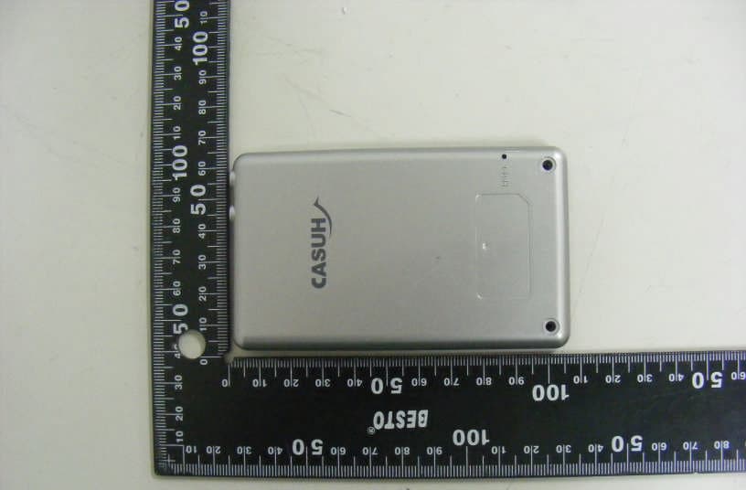
Click to zoom
Application Details
- Equipment Class
- DSS - Part 15 Spread Spectrum Transmitter
- Date of Grant
- Jul 17, 2010
- Application Purpose
- Original Equipment
- Date of Application
- Jul 17, 2010
- Equipment Note
- Portable Conference Transmitter
- Frequency Range
- 2402.00000000 - 2476.00000000
- Company
- Williams Sound, LLC
- Country
- United States
Documents & Files
Document Text
Text extracted from the exhibit documents filed with the FCC. Open a document above to read the original.
Users Manual
DLT-100 User Guide DLT-100 User Guide 1 What’s included with DLT-100 What’s included with DLT-100 2 ①DLT-100 ②USB Cable ③Adaptor ④Plug 1 (Europe) ⑤Plug 2 (England) ⑥Plug 3 (Australia) ①② ③ ④⑤⑥ Location of Controls Location of Controls 3 Function Button LED LCD Display Speaker ⑤External Mic. Jack(3.5mm) ⑥External Headphone Jack(3.5mm) Microphone Ipod connector (30Pin) Reset Button Simultaneous Interpretation Mode Simultaneous Interpretation Mode 4 Simultaneous Interpretation Mode Simultaneous Interpretation Mode 5 Press and hold power button for 2 seconds to turn DLT- 100 on 1 1. Setting procedure for Interpretation Mode Press No and Yes button together for 2 second Mode icon will blink on LCD 2 Press ( +) or (– )button to select mode 3 Press (-) button, the mode will be changed in above sequence. Press (+) button, reverse sequence. Main Speaker Interpreter AP(relay) Receiver only Note In Interpretation Mode 3 different mode can be used as shown in left side. Each has different role but they all can be used un Interpretation system Simultaneous Interpretation Mode Simultaneous Interpretation Mode 6 1. Setting procedure for Interpretation Mode 4 Press mode button to select interpretation mode 5 When mode selection is made then SLV icon will blink 6 Press ( +) or (– )button to select SLV or MAS SLV- Slave MAS-Master Press ( +) or (– )button to select transmitting channel number 8 7 Press mode button to select SLV or MAS 1 Note When channel number is at No.1, (-) button will not work 9 Press mode button to select channel number 10 When channel number selection is made then Group icon will blink and number will be shown 12 Press ( +) or (– )button to select group number Simultaneous Interpretation System Simultaneous Interpretation System 7 1.Setting procedure for Interpretation System 11 Press mode button to select group number Note If your unit is set to MAS go to next page Skip procedure 12 and do procedure 13 Press No and Yes button together for 2 second to complete setting 12 Final setting for slave unit Simultaneous Interpretation System Simultaneous Interpretation System 8 1.Setting procedure for Interpretation System 11 Press mode button to select group number Press No and Yes button together for 2 second to complete setting 15 Final setting for Master unit Press ( +) or (– )button to adjust minute When group number selection is made then number of hour will blink 14 Press mode button to complete Hour setting 16 Note: 1.Master and Slave unit must have same group number 2.Transmitting Channel must be set different 3.Must have one master in a group Press ( +) or (– )button to adjust Hour 13 Simultaneous Interpretation Mode Simultaneous Interpretation Mode 9 CASE1) Interpreter -3 units Receiver – 20 units English Ch1 Chinese Ch2 Korean Ch3 Select Channel and Listen CASE2) Main Speaker is set to “0” Channel Main Speaker -1 units Interpreter – 2 units Receiver – 20 units Interpreter -A Ch1 Interpreter –B Ch2 Select Channel and Listen CASE3) Interpreter-1 units AP(Relay) – 1 units Receiver – 20 units Interpreter -A Ch1 AP (=Repeater) Extend the distance Two-way tour guide mode (conference mode) Two-way tour guide mode (conference mode) 10 Press and hold power button for 2 seconds to turn DLT- 100 on 1 2. Setting procedure for Two-way tour guide mode(conference mode) ÆMode change from interpretation to Two-way tour guide mode Press No and Yes button together for 2 second Mode icon will blink on LCD 2 Press ( +) or (– )button to select mode 3 Press (-) button, the mode will be changed in above sequence. Press (+) button, reverse sequence. 4 Press mode button to select tour guide system 5 When mode selection is made then CHAIRMAN SLV will blink 6 Press ( +) or (– )button to select CHAIRMAN /SLV, CHAIRMAN /MAS, SLV 4 Select tour guide system Two-way tour guide mode (conference mode) Two-way tour guide mode (conference mode) 11 Press ( +) or (– )button to set address number (0~1023) 8 9 Press mode button to set address number 10 11 7 Press mode button to select CHAIRMAN /SLV, CHAIRMAN /MAS, SLV When address setting is made then Group icon will blink and number will be shown 73 When CHAIRMAN MAS Selection is made then address icon will blink and number will be shown 14 Press ( +) or (– )button to select group number Press mode button to select group number Note If your unit is set to CHAIRMAN/MAS go to next page Skip procedure 12 and do procedure 13 Press No and Yes button together for 2 second to complete setting 12 Final setting for slave unit 2. Setting procedure for Two-way tour guide mode(conference mode) 73 Two-way tour guide mode (conference mode) Two-way tour guide mode (conference mode) 12 11 Press mode button to select group number 15 Final setting for Master unit Press ( +) or (– )button to adjust minute When group number selection is made then Time icon will blink 14 Press mode button to complete Hour setting 16 2. Setting procedure for Two-way tour guide mode(conference mode) Press ( +) or (– )button to adjust Hour 13 Press mode button to complete time setting When time setting is made then speech time talk icon will blink Press ( +) or (– )button to adjust speech time in minute (up to 60 Min.) 17 Two-way tour guide mode (conference mode) Two-way tour guide mode (conference mode) 13 Press No and Yes button together for 2 second to complete setting 2. Setting procedure for Two-way tour guide mode(conference mode) Note If you don’t want to set speech time, please set speech time to “0” 18 Note: 1.Master and Slave unit must have same group number 2.Must have one master in a group Two-way tour guide mode (conference mode) Two-way tour guide mode (conference mode) 14 CASE1) Tour guide phone-2 units Receiver – 20 units EnglishChinese Just Listen CASE2) Tour guide phone-3 units Receiver – 20 units Two people can talk at the same time Two way communication Just Listen Troubleshooting Troubleshooting •A/S phone Number: 952-943-2252 •Williams Sound Corp. A/S Team •10321 West 70 th Street Eden …
Text truncated - open the document above for the full version.
Cover Letter(s)
Federal Communications Commission 7435 Oakland Mills Road Columbia, MD 21046 Gentlemen: This letter is to comply with Section 0.457(d)(2)(i) and 0.459 pertaining to confidential material. We, Williams Sound Corp., would like the following documents regarding this submission for FCC ID: CNMDLT100 to be kept confidential. 1. Schematics 2. Operating description 3. Block Diagram The above material contains trade secrets or technical data, which would customarily be guarded from competitors. We do not want these documents to be accessible to the general public. Sincerely, Gregg E. Abram Williams Sound Corp.
External Photos
External photos of EUT Front view of EUT Rear view of EUT Top view of EUT Bottom view of EUT Right view of EUT Left view of EUT
ID Label/Location Info
FCC/IC Label 1. FCC/IC Label Drawing 2. FCC/IC Label Location Williams Sound Corporation. Model : DLT100 FCC ID : CNMDLT100 IC: 1360A-DLT100
Internal Photos
Internal photos of EUT Top view of Main PCB Bottom view of Main PCB RF module Antenna
RF Exposure Info
Report File No. : F690501/RF-SAR001875-A1 Date of Issue : 2010-07-15 Page : 2 / 67 Contents 1. General Information 1.1 Testing Laboratory........................................................................................... 3 1.2 Details of Applicant.......................................................................................... 3 1.3 Version of Report............................................................................................. 3 1.4 Description of EUT(s)....................................................................................... 3 1.5 Test Environment............................................................................................. 4 1.6 Operation description........................................................................................ 4 1.7 Evaluation procedures....................................................................................... 5 1.8 The SAR Measurement System............................................................................ 6 1.9 System Components.......................................................................................... 8 1.10 SAR System Verification.................................................................................... 9 1.11 Tissue Simulant Fluid for the Frequency Band.......................................................... 11 1.12 Test Standards and Limits.................................................................................. 12 2. Instruments List.................................................................................... 14 3. Summary of Results................................................................................ 15 APPENDIX A. Photographs of EUT & EUT’s Test Setup B. DASY4 SAR Report C. Uncertainty Analysis D. Calibration certificate Report File No. : F690501/RF-SAR001875-A1 Date of Issue : 2010-07-15 Page : 3 / 67 1. General Information 1.1 Testing Laboratory SGS Testing Korea Co., Ltd. Wireless Div. 2FL, 18-34, Sanbon-dong, Gunpo-si, Gyeonggi-do, Korea 435-040 Telephone : +82 +31 428 5700 FAX : +82 +31 427 2371 Homepage : www.kr.sgs.com/ee 1.2 Details of Manufacturer Manufacturer : Williams Sound Corp. Address : 10321 W. 70 th Street, Eden Prairie, Minnesota, 55344, USA Contact Person : Gregg Abram Phone No. : 952-224-7703 Fax No. : 952-224-7786 1.3 Version of Report Version Number Date Revision 00 2010-07-07 Initial issue 01 2010-07-15 Revision 01 1.4 Description of EUT(s) EUT Type : Portable Conference Transmitter Model : DLT100 Serial Number : N/A Mode of Operation : 2.4GHz Transmitter Duty Cycle : 100 % Body worn Accessory : None Tx Frequency Range : 2402 MHz ~ 2476 MHz Conducted Max Power : 15.40 dBm Battery Type : DC 3.7 V Report File No. : F690501/RF-SAR001875-A1 Date of Issue : 2010-07-15 Page : 4 / 67 1.5 Test Environment Ambient temperature : 21 ° C ~ 23 ° C Tissue Simulating Liquid : 21 ° C ~ 23 ° C Relative Humidity : 40 % ~ 60 % 1.6 Operation Configuration The client provided a special driver and test program which can control the frequency and power of the module. Measurements were performed at the lowest, middle and highest channels of the operating band. The EUT was set to maximum power level during all tests and at the beginning of each test the battery was fully charged. The DASY4 system measures power drift during SAR testing by comparing e-field in the same location at the beginning and at the end of measurement. Report File No. : F690501/RF-SAR001875-A1 Date of Issue : 2010-07-15 Page : 5 / 67 1.7 EVALUATION PROCEDURES - Power Reference Measurement Procedures The Power Reference Measurement and Power Drift Measurements are for monitoring the power drift of the device under test in the batch process. The Minimum distance of probe sensors to surface determines the closest measurement point to phantom surface. The minimum distance of probe sensors to surface is 4 mm. This distance cannot be smaller than the Distance of sensor calibration points to probe tip as defined in the probe properties (for example, 2.7 mm for an ET3DV6 probe type). - The entire evaluation of the spatial peak values is performed within the Post-processing engine (SEMCAD). The system always gives the maximum values for the 1 g and 10 g cubes. The algorithm to find the cube with highest averaged SAR is divided into the following stages: 1. The extraction of the measured data (grid and values) from the Zoom Scan. 2. The calculation of the SAR value at every measurement point based on all stored data (A/D values and measurement parameters) 3. The generation of a high-resolution mesh within the measured volume 4. The interpolation of all measured values from the measurement grid to the high-resolution grid 5. The extrapolation of the entire 3-D field distribution to the phantom surface over the distance from sensor to surface 6. The calculation of the averaged SAR within masses of 1 g and 10 g. The probe is calibrated at the center of the dipole sensors that is located 1 to 2.7 mm away from the probe tip. During measurements, the probe stops shortly above the phantom surface, depending on the probe and the surface detecting system. Both distances are included as parameters in the probe configuration file. The software always knows exactly how far away the measured point is from the surface. As the probe cannot directly measure at the surface, the values between the deepest measured point and the surface must be extrapolated. The angle between the probe axis and the surface normal line is less than 30 degree. In the Area Scan, the gradient of the interpolation function is evaluated to find all the extreme of the SAR distribution. The uncertainty on the locations of the extreme is less than 1/20 of the grid size. Only local maximum within –2 dB of the global maximum are searched and passed for the Cube Scan measurement. In the Cube Scan, the interpolation function is used to extrapolate the Peak SAR from the lowest measurement points to the i…
Text truncated - open the document above for the full version.
Test Report
Report Number: F690501/RF-RTL003949Page: 2 of 45 The results shown in this test report refer only to the sample(s) tested unless otherwise stated. This test report cannot be reproduced, except in full, without prior written permission of the Company. SGS Testing Korea Co., Ltd. 18-34, Sanbon-dong, Gunpo-si, Gyeonggi-do, Korea, 435-040 Tel. +82 31 428 5700 / Fax. +82 31 427 2371www.electrolab.kr.sgs.com Table of contents 1. General information --------------------------------------------------------------------------------------3 2. Transmitter radiated spurious emissions and conducted spurious emission --------------8 3. Receiver Radiated Spurious Emission--------------------------------------------------------------- 18 4. 20໒bandwidth and 99 % BW------------------------------------------------------------------------ 20 5. Maximum peak output power -------------------------------------------------------------------------- 25 6. Hopping channel separation --------------------------------------------------------------------------- 28 7. Number of hopping frequency ------------------------------------------------------------------------- 31 8. Time of occupancy(Dwell time) ----------------------------------------------------------------------- 34 9. Transmitter AC Power Line Conducted Emission------------------------------------------------- 36 10. Receiver AC Power Line Conducted Emission--------------------------------------------------- 41 11. Antenna requirement ----------------------------------------------------------------------------------- 45 Report Number: F690501/RF-RTL003949Page: 3 of 45 The results shown in this test report refer only to the sample(s) tested unless otherwise stated. This test report cannot be reproduced, except in full, without prior written permission of the Company. SGS Testing Korea Co., Ltd. 18-34, Sanbon-dong, Gunpo-si, Gyeonggi-do, Korea, 435-040 Tel. +82 31 428 5700 / Fax. +82 31 427 2371www.electrolab.kr.sgs.com 1. General information 1.1 Testing laboratory SGS Testing Korea Co., Ltd. Wireless Div. 2FL, 18-34, Sanbon-dong, Gunpo-si, Gyeonggi-do, Korea 435-040 www.electrolab.kr.sgs.com Telephone:+82 +31 428 5700 FAX: +82 +31 427 2371 1.2 Details of applicant Applicant: Williams Sound Corp. Address: 10321 W. 70 th Street, Eden Prairie, Minnesota, 55344, USA Contact Person : Gregg Abram Phone No.: +1 952 224 7703 Fax No.: +1 952 224 7786 1.3 Description of EUT Kind of Product Portable Conference Transmitter Model Name DLT100 Serial Number N/A Power Supply DC 3.7 V(Lithum battery) Frequency Range 2 402~ 2 476 Modulation Technique GFSK Number of Channels 16 Channel Separation 2(Tour guide mode), 5(Interpretation mode) Antenna Type Integral Type Antenna Gain -0.22໒i 1.4 Details of modification ඖTwo Mode are almost same as that excepting channel separation. Report Number: F690501/RF-RTL003949Page: 4 of 45 The results shown in this test report refer only to the sample(s) tested unless otherwise stated. This test report cannot be reproduced, except in full, without prior written permission of the Company. SGS Testing Korea Co., Ltd. 18-34, Sanbon-dong, Gunpo-si, Gyeonggi-do, Korea, 435-040 Tel. +82 31 428 5700 / Fax. +82 31 427 2371www.electrolab.kr.sgs.com 1.5. Information about the FHSS characteristics: 1.5.1. Pseudorandom Frequency Hopping Sequence The channel is represented by a 4 frequency hopping sequence hopping through the 16 RF channels. The channel is divided into time slots where each slot corresponds to an RF hop frequency. Consecutive hops correspond to different RF hop frequencies. The nominal hop rate is 325 hops/s. 1.5.2. Equal Hopping Frequency Use There are two modes in DLT 100 operation and which have different frequency table. In result, the center frequency table for tour guide mode is as below: (Each center frequency, Unit: MHz) No 12345678910 11 12 13 14 15 16 1 2402 2404 2406 2408 2422 2424 2426 2428 2442 2444 2446 2448 2462 2464 2466 2468 2 2412 2414 2416 2418 2432 2434 2436 2438 2452 2454 2456 2458 2470 2472 2474 2476 3 2407 2409 2411 2413 2427 2429 2431 2433 2447 2449 2451 2453 2467 2469 2471 2473 4 2403 2405 2417 2419 2421 2423 2437 2439 2441 2443 2457 2459 2461 2463 2473 2475 This table is also used to synchronize in the same group. The center frequency table for the other mode, interpretation mode, is as below: (Each center frequency, Unit: MHz) No12345678910111213141516 1 2402 2407 2412 2417 2422 2427 2432 2437 2442 2447 2452 2457 2462 2467 2472 2476 2 2403 2408 2413 2418 2423 2428 2433 2438 2443 2448 2453 2458 2463 2468 2473 2456 3 2404 2409 2414 2419 2424 2429 2434 2439 2444 2449 2454 2459 2464 2469 2474 2436 4 2405 2410 2415 2420 2425 2430 2435 2440 2445 2450 2455 2460 2465 2470 2475 2416 5 2417 2412 2407 2402 2437 2432 2427 2422 2457 2452 2447 2442 2476 2472 2467 2462 6 2418 2413 2408 2403 2438 2433 2428 2423 2458 2453 2448 2443 2456 2473 2468 2463 7 2419 2414 2409 2404 2439 2434 2429 2424 2459 2454 2449 2444 2436 2474 2469 2464 8 2420 2415 2410 2405 2440 2435 2430 2425 2460 2455 2450 2445 2416 2475 2470 2465 1.5.3. System Receiver Input Bandwidth Each channel bandwidth is 1 Report Number: F690501/RF-RTL003949Page: 5 of 45 The results shown in this test report refer only to the sample(s) tested unless otherwise stated. This test report cannot be reproduced, except in full, without prior written permission of the Company. SGS Testing Korea Co., Ltd. 18-34, Sanbon-dong, Gunpo-si, Gyeonggi-do, Korea, 435-040 Tel. +82 31 428 5700 / Fax. +82 31 427 2371www.electrolab.kr.sgs.com 1.6 Test equipment list EQUIPMENTMANUFACTURERMODELCAL DUE. Signal GeneratorR & S SMR40 Sep. 25, 2010 Spectrum AnalyzerR & SFSV30May. 31, 2011 Spectrum AnalyzerR & SFSP40Sep 25, 2010 PreamplifierH.P8447FJul. 07, 2011 PreamplifierAgilent8449BMar. 31, 2011 High Pass FilterWainwrightWHK3.0/18G-10SS Sep. 29, 2010 DC power SupplyAgilentU8002AJan. 06, 2011 Test ReceiverR & SESU26Apr. 08, 2011 Bilog Antenna SCHWARZBECK MESSELEKTRONIK VULB9163Jul. 22, 2010 Horn…
Text truncated - open the document above for the full version.
Test Setup Photos
Test setup photos of EUT A. Photo of Field Strenght & Spurious Emission Test B. Photo of conducted power line test
Contact Information
Applicant
Per W. Danzl(VP of Engineering)
Test Firm
SGS Korea Co., Ltd.Julia Choi
Technical Specifications
| # | Rule Parts | Frequency Range | Power Output |
|---|---|---|---|
| 1 | 15C | 2.40 GHz - 2.48 GHz | 37.20 mW |
Other Applications from Williams Sound, LLC
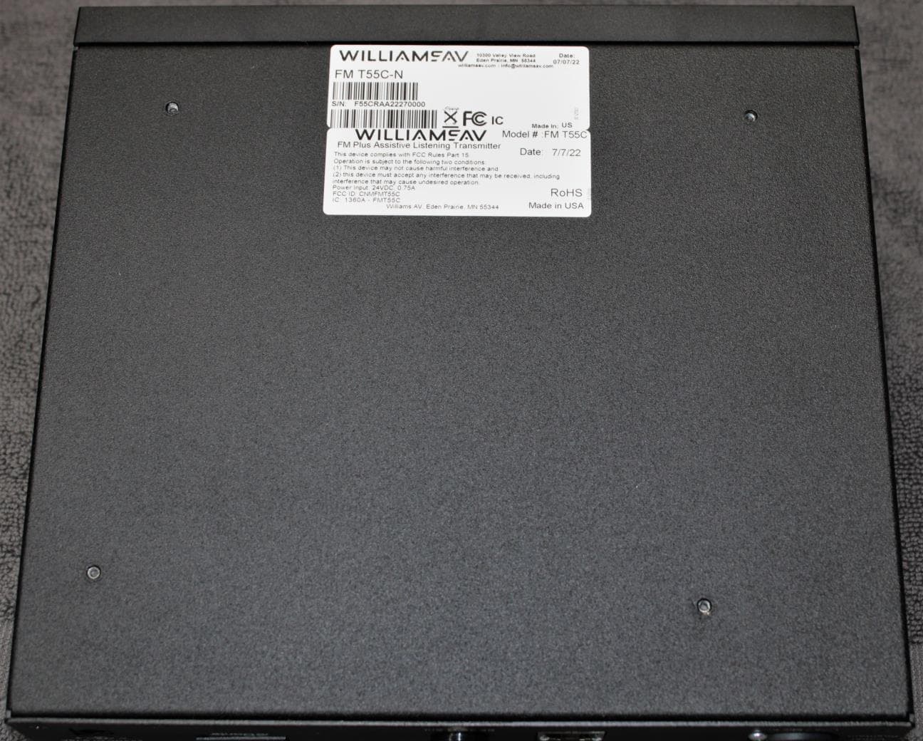
CNMFMT55C
Aug 28, 2022FM T55C
Equipment Class
GAT - Part 15 Auditory Assistance Device (Transmitter)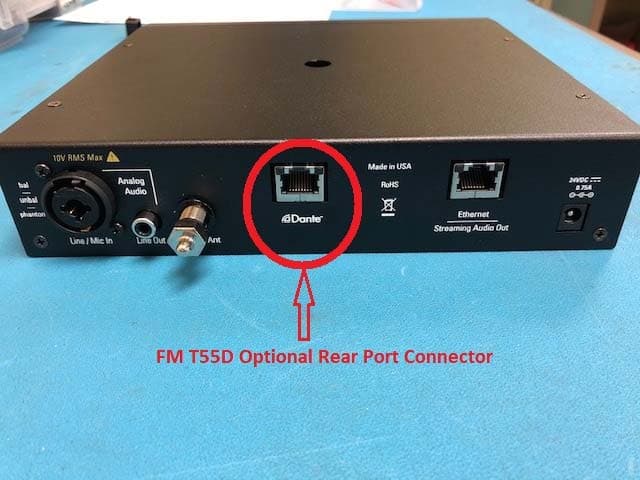
CNMFMT55
Mar 12, 2020FM T55, FM T55D
Equipment Class
GAT - Part 15 Auditory Assistance Device (Transmitter)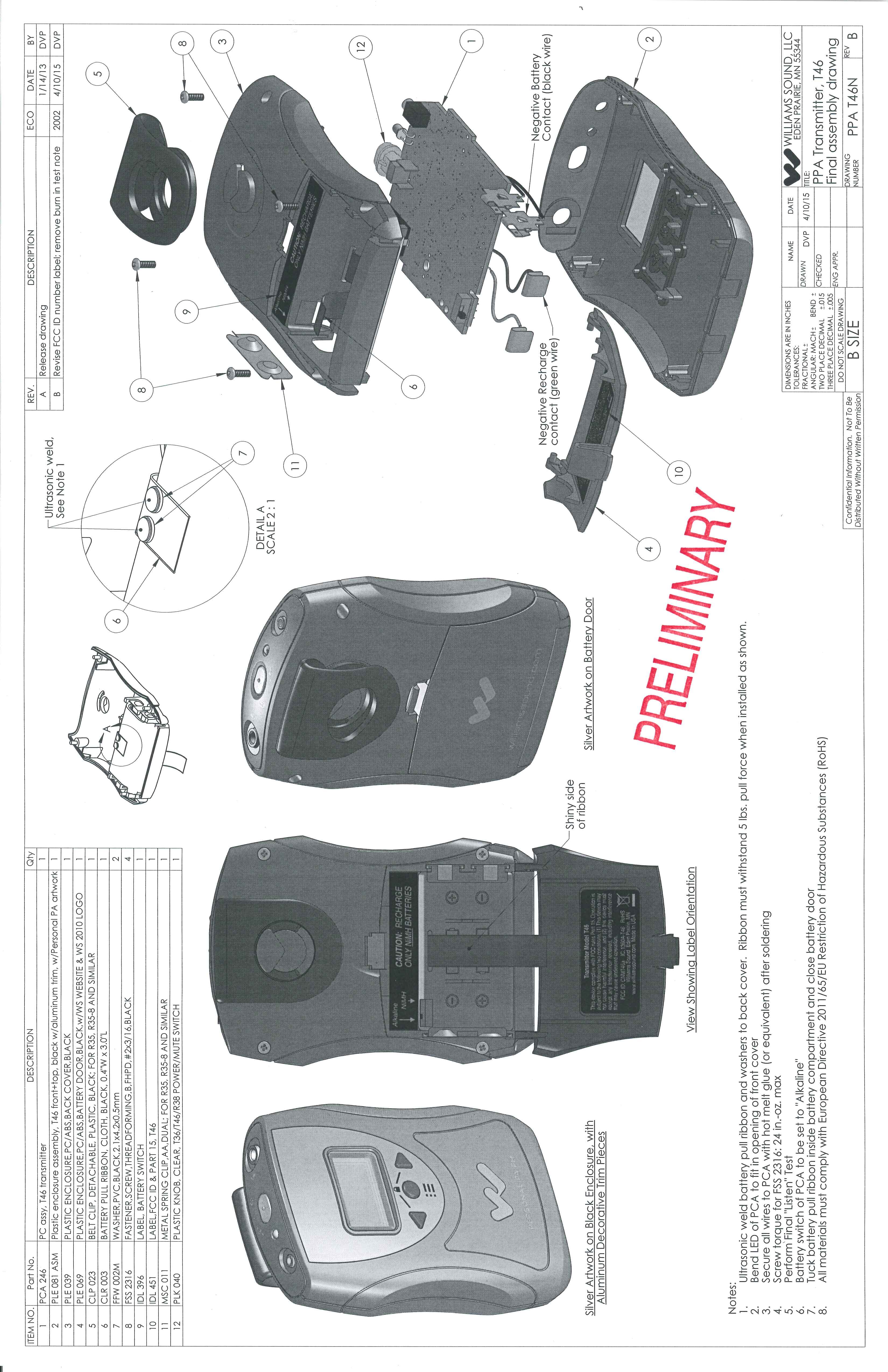
CNMT46A
May 03, 2015Battery operated auditory assistance transmitter
Equipment Class
DXT - Part 15 Low Power Transceiver, Rx Verified
CNMDLT300
Nov 20, 2014Portable Conference Transmitter
Equipment Class
DSS - Part 15 Spread Spectrum Transmitter
CNMT46
Oct 04, 2012Portable Hearing Assistance Transmitter
Equipment Class
GAT - Part 15 Auditory Assistance Device (Transmitter)