CNMFMT55FM T55, FM T55D
Williams Sound, LLC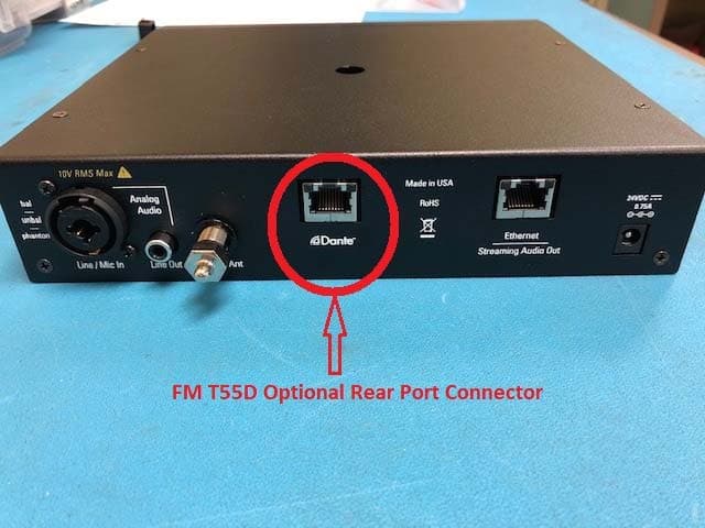
Click to zoom
Application Details
- Equipment Class
- GAT - Part 15 Auditory Assistance Device (Transmitter)
- Date of Grant
- Mar 12, 2020
- Application Purpose
- Original Equipment
- Date of Application
- Mar 12, 2020
- Equipment Note
- FM T55, FM T55D
- Frequency Range
- 75.30000000 - 75.90000000
- Company
- Williams Sound, LLC
- Country
- United States
Documents & Files
Document Text
Text extracted from the exhibit documents filed with the FCC. Open a document above to read the original.
Users Manual
FM + Assistive Listening System FM T55 USER MANUAL MAN 245C 2 FM + Table of Contents Safety Warnings and Instructions ��������������������������������������������������������������������������������������������������������������������������������������������3 Recycling Instructions ����������������������������������������������������������������������������������������������������������������������������������������������������������������3 System Overview ������������������������������������������������������������������������������������������������������������������������������������������������������������������������4 Quick Setup Instructions �����������������������������������������������������������������������������������������������������������������������������������������������������������5 Wi-Fi Network May Be Required ����������������������������������������������������������������������������������������������������������������������������������������������6 Router and Network Equipment Selection �����������������������������������������������������������������������������������������������������������������������������6 Wiring and Connections ������������������������������������������������������������������������������������������������������������������������������������������������������������6 Ethernet and Dante RJ-45 Connection ���������������������������������������������������������������������������������������������������������������������������������������������7 Audio Source Connections �������������������������������������������������������������������������������������������������������������������������������������������������������������������7 Multi-Channel Sources ���������������������������������������������������������������������������������������������������������������������������������������������������������������������������7 Connecting Additional Sound Systems ���������������������������������������������������������������������������������������������������������������������������������������������7 Avoiding Hum in the Audio (as a Result of a Ground Loop) ���������������������������������������������������������������������������������������������������������8 Selecting an Audio Source Appropriate for Hearing Impaired Listeners ���������������������������������������������������������������������������������8 Installing the ANT 025 Whip Antenna �����������������������������������������������������������������������������������������������������������������������������������������������8 Connecting to other Devices ���������������������������������������������������������������������������������������������������������������������������������������������������������������9 Controls and Features �������������������������������������������������������������������������������������������������������������������������������������������������������������10 System Settings �������������������������������������������������������������������������������������������������������������������������������������������������������������������������11 Audio Settings ������������������������������������������������������������������������������������������������������������������������������������������������������������������������������������������11 Audio Source ��������������������������������������������������������������������������������������������������������������������������������������������������������������������������������������������11 Audio Input Gain ��������������������������������������������������������������������������������������������������������������������������������������������������������������������������������������11 Audio Presets �������������������������������������������������������������������������������������������������������������������������������������������������������������������������������������������11 High-pass Filter ��������������������������������������������������������������������������������������������������������������������������������������������������������������������������������������12 Low-pass Filter ���������������������������������������������������������������������������������������������������������������������������������������������������������������������������������������12 Compression ������������������������������������������������������������������������������������������������������������������������������������������������������������������������������������������12 Headphone Volume ������������������������������������������������������������������������������������������������������������������������������������������������������������������������������12 FM Output Power ����������������������������������������������������������������������������������������������������������������������������������������������������������������������������������12 Time-Out ��������������������������������������������������������������������������������������������������������������������������������������������������������������������������������������������������12 Screen Lock ��������������������������������������������������������������������������������������������������������������������������������������������������������������������������������������������12 User-Entered Transmitter Description ����������������������������������������������������������������������������������������������������������������������������������������������13 Channel �����������������������������������������������������������������������������������������������������������������������������������������������������������������������������������������������������13 Restore Defaults �������������������������������������������������������������������������������������������������������������������������������������������������������������������������������������13 Network Settings ����������������������������������������…
Text truncated - open the document above for the full version.
External Photos
Addendum: FCC/IC Testing General Product Information for FM T55 Transmitter – Optional FM T55D (Dante audio input) The optional Model FM T55D appears nearly identical to the FM T55 in external views, with the exception of an additional rear port for the Dante audio input connection, shown in the red circle in photo below, and the FCC/ISED label on the bottom containing the indicated model option for that unit which is shown in the next photo. Model Option: FM T55D, Back of unit, showing additional Dante Port. Model Option: FM T55D: Bottom of unit showing FM T55D model option label.
External Photos
FCC/IC Testing General Product Information for FM T55 Transmitter Contact Information: Send Reports To and File Under Name of: Gregg Abram, Chief Technical Officer Direct: 952‐224‐7703 Email: [email protected] Technical Lead: Butch Herrington, Principal RF Engineer Direct: 952‐224‐7721 Email: [email protected] Company Information: Williams Sound, LLC 10300 Valley View Road Eden Prairie, MN 55344 1‐800‐328‐6190 Model#: FM T55 FM T55 D FCC ID: CNMFMT55 ISED ID: IC: 1360A‐FMT55 Brief Description: The FM T55 is a Wideband base station FM transmitter operating on 17 channels between 72‐76MHz. At full power, the transmitter has up to 1000 foot transmission range using an ANT 005 antenna. When used as a system with compatible FM receivers, it provides for hearing assistance by allowing a group of people to listen directly to the sound source without interference from background noise or distance. It has an OLED display which indicates transmission frequency, antenna output power setting, and audio settings. Current audio level is displayed by a set of 10 green, yellow, and red LED’s. The unit can be controlled through a 5‐button control set on the face of the unit, or through its hosted webpage. Audio is input through the analog XLR/¼” phone combo jack input selectable between microphone and line level sources, or the optional Dante connector. Audio is output through a line level RCA jack on the back panel, a ¼” headphone jack on the front panel, through streaming on the Ethernet jack for WiFi broadcast through a separate network, and via RF transmission to receivers. Additional Information contained in T55 Theory of Operation.docx and the T55 User’s Manual, MAN245. FCC Label Location: FCC Label (IDZ08) to be located on the bottom of the unit as shown in product photos. We are seeking FCC approval under FCC part 15.237 as a class II permissive device. We intend to market the product in the US and Canada. External Power Supply, Williams Sound part number TFP 062 Front Face of Unit Back of unit Left Side of Unit Right Side of Unit Bottom of unit showing FCC ID label Top of Unit ANT 005 Coaxial Dipole Antenna ANT 021 Rubber Duckie Antenna ANT 024 Dipole Telescoping Whip Antenna ANT 025 Telescoping Whip Antenna
ID Label/Location Info
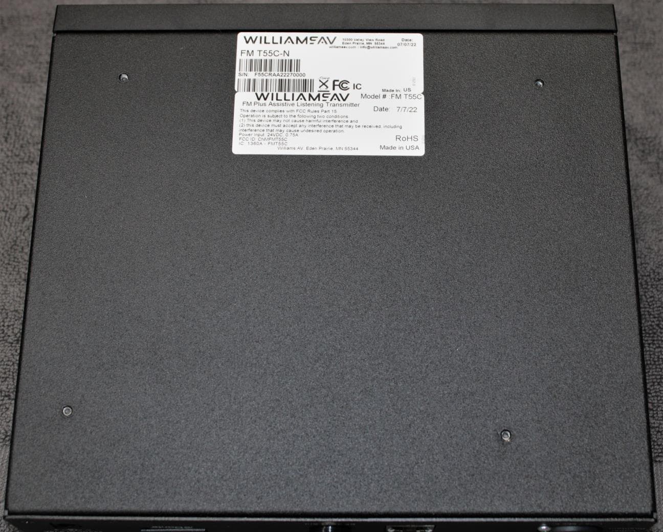
Label and Location for FCC ID and Industry Canada ID Model#: FM T55 FM T55 D FCC ID: CNMFMT55 ISED ID: IC: 1360A‐FMT55 FCC Label (IDZ08) to be located on the bottom of the unit as shown in product photos below. Bottom of unit showing FCC and IC ID label location
Internal Photos
Williams AV - FM T55 Internal Photos-01.docx FM T55 Internal Photos (Part 1) The following internal photos are for the individual boards that are used in the FM T55. The FM Radio section is highlighted with text and circled sections within the main system board. Photo Enlargements of the critical RF radio sections are included for purposes of readability. To comply with 6 MB file size limits, this set of photos is broken into three sections, with the following file names: FM T55 Internal Photos-01.docx FM T55 Internal Photos-02.docx FM T55 Internal Photos-03.docx The functional circuit description for each element is described in the “FM T55 Theory of Operation and Circuit Description”, RF Radio Circuits, pages 8-10. Associated Schematics for the RF Radio section referenced in the photos, are included in the file for SCH 294, the FM T55 motherboard. Photo1: Internal Top view of system main board (PCA 294) installed in chassis, and showing location of key RF radio sections. Photo 2: PCA 294 board removed from chassis, and shield cover removed from RF radio section. (Next Photos 3,4 are enlargements of the two RF circuits circled above in white.) Photo 10: FM T55D (Dante) model option, showing added Dante module. (Note: Dante Module is an externally sourced digital audio input module) Photo 11: PCA D-300, top view (Dante Module) Photo 12: PCA D-300, bottom view (Dante Module) Williams AV - FM T55 Internal Photos-03B.docx FM T55 Internal Photos (Part 03B) The following internal photos are for the individual boards that are used in the FM T55. The FM Radio section is highlighted with text and circled sections within the main system board. Photo Enlargements of the critical RF radio sections are included for purposes of readability. Photo 8: Top Side, PCA 293, Ethernet interface and system microcontroller Photo 9: Bottom Side, PCA 293, Ethernet interface and system microcontroller. Williams AV - FM T55 Internal Photos-03A.docx FM T55 Internal Photos (Part 03A) The following internal photos are for the individual boards that are used in the FM T55. The FM Radio section is highlighted with text and circled sections within the main system board. Photo Enlargements of the critical RF radio sections are included for purposes of readability. Photo 6: Top Side, PCA 295 (Front control panel (bezel)). Photo 7: Bottom Side, PCA 295 (Front control panel (bezel)). Williams AV - FM T55 Internal Photos-02.docx FM T55 Internal Photos (Part 2) The following internal photos are for the individual boards that are used in the FM T55. The FM Radio section is highlighted with text and circled sections within the main system board. Photo Enlargements of the critical RF radio sections are included for purposes of readability. The functional circuit description for each element is described in the “FM T55 Theory of Operation and Circuit Description”, RF Radio Circuits, pages 8-10. Associated Schematics for the RF Radio section referenced in the photos, are included in the file for SCH 294, the FM T55 motherboard. Photo 3: Enlargement of main RF radio section, including reference oscillator, PLL, tuner and modulator sections. Associated schematic components are located on Schematic SCH 294 Sheet 1. Photo 4: Enlargement of RF Gain section, including filters and drive circuit for antennae. Associated Schematic components are located on Schematic SCH 294, Sheet 2. Component IC6, Pin 3 is the RF Power monitor output that feeds microcontroller IC30, pin 7, on schematic Sheet 6. Photo 5: Bottom side, PCA 294.
Operational Description
FM T55 Antenna Information The FM T55 is a base station transmitter operating in the 72‐76MHz band. We offer 4 antennas for sale with this product: ANT 005 o Manufactured by Lee Manufacturing, p/n ANT 005A o This is a remote coaxial antenna. It includes a 22 foot long overall cable, with an 80” section providing the active antenna. o Gain of 2.4dBi max – dipole. o See ANT005a.pdf for specification drawing. ANT 021 o Manufactured by Mobiltec, p/n AM168‐02 / ANT 021 rev D o This is a rubber ducky antenna, it is 9” long, and is screwed directly onto the transmitter PCB. o Gain of ‐3dBi dBi max o See ANT021d.pdf for specification drawing ANT 024 o Manufactured by Williams Sound, LLC, p/n ANT 024 o This is a wall mounted telescoping dipole whip antenna for remote installation, it is 40” long with both whips fully extended. o Gain of 0dBi max o See ANT024d.pdf for specification drawing ANT 025 o Manufactured by Williams Sound, LLC, p/n ANT 024 o This is a PCB mount telescoping whip antenna. It is 39” long when fully extended. o Gain of 2.4dBi max o See ANT025c.pdf for specification drawing These antennas comply with FCC 15.203: Two of these antennas mount by a non‐standard screw post (or stud) through a hole in the top cover of the chassis. No other known antennas will mate with this socket. ANT 021, ANT 025. The other two antennas attach to a connector on the back of the unit. The connector they are attached to is disabled with a permanently attached cap when not used. ANT 005 and ANT 024. All of these antennas have been tested and verified to radiate less than the maximum of 8000uV/m at 3 meters permitted to this type of equipment, when connected to the T55 transmitter with a radiated output as set by the manufacturer.
Test Report
This report must not be used to claim product certification, approval, or endorsement by NVLAP, NIST, or any agency of the U.S. Government. This Report shall not be reproduced, except in full without written approval of the laboratory. Williams Sound, LLC FM T55 FCC 15.237:2019 Transmit only 72-76 MHz Report # WILM0050.2 NVLAP LAB CODE: 200881-0 CERTIFICATE OF TEST 2018-09-14 Product compliance is the responsibility of the client; therefore, the tests and equipment modes of operation represented in this report were agreed upon by the client, prior to testing. The results of this test pertain only to the sample(s) tested. The specific description is noted in each of the individual sections of the test report supporting this certificate of test. This report reflects only those tests from the referenced standards shown in the certificate of test. It does not include inspection or verification of labels, identification, marking or user information. As indicated in the Statement of Work sent with the quotation, Element’s standard process is to always use the latest published version of the test methods even when earlier versions are cited in the test specification. Issuance of a purchase order was de facto acceptance of this approach. Otherwise, the client would have advised Element in writing of the specific version of the test methods they wanted applied to the subject testing. Last Date of Test: September 3, 2019 Williams Sound, LLC Model: FM T55 Radio Equipment Testing Standards Specification Method FCC 15.207:2019 ANSI C63.10:2013 FCC 15.237:2019 Results Method Clause Test Description Applied Results Comments 6.2 Powerline Conducted Emissions Yes Pass 6.5 Field Strength of Fundamental Yes Pass 6.5, 6.6 Field Strength of Harmonics and Spurious Radiated Emissions Yes Pass 7.5 Occupied Bandwidth Yes Pass 7.5 Duty Cycle No N/A Not applicable. Assumes 100% on time. Deviations From Test Standards None Approved By: Matt Nuernberg, Operations Manager Report No. WILM0050.22/51 REVISION HISTORY 2018.07.17 Revision Number Description Date (yyyy-mm-dd) Page Number 00 None Report No. WILM0050.23/51 ACCREDITATIONS AND AUTHORIZATIONS 2019.03.08 United States FCC - Designated by the FCC as a Telecommunications Certification Body (TCB). Certification chambers, Open Area Test Sites, and conducted measurement facilities are listed with the FCC. A2LA - Accredited by A2LA to ISO / IEC 17065 as a product certifier. This allows Element to certify transmitters to FCC and IC specifications. NVLAP - Each laboratory is accredited by NVLAP to ISO 17025 Canada ISED - Recognized by Innovation, Science and Economic Development Canada as a Certification Body (CB) and as a CAB for the acceptance of test data. European Union European Commission – Within Element, we have a EU Notified Body validated for the EMCD and RED Directives. Australia/New Zealand ACMA - Recognized by ACMA as a CAB for the acceptance of test data. Korea MSIT / RRA - Recognized by KCC’s RRA as a CAB for the acceptance of test data. Japan VCCI - Associate Member of the VCCI. Conducted and radiated measurement facilities are registered. Taiwan BSMI – Recognized by BSMI as a CAB for the acceptance of test data. NCC - Recognized by NCC as a CAB for the acceptance of test data. Singapore IDA – Recognized by IDA as a CAB for the acceptance of test data. Israel MOC – Recognized by MOC as a CAB for the acceptance of test data. Hong Kong OFCA – Recognized by OFCA as a CAB for the acceptance of test data. Vietnam MIC – Recognized by MIC as a CAB for the acceptance of test data. SCOPE For details on the Scopes of our Accreditations, please visit: https://www.nwemc.com/emc-testing-accreditations Report No. WILM0050.24/51 FACILITIES 2019.03.08 California Labs OC01-17 41 Tesla Irvine, CA 92618 (949) 861-8918 Minnesota Labs MN01-10 9349 W Broadway Ave. Brooklyn Park, MN 55445 (612)-638-5136 Oregon Labs EV01-12 6775 NE Evergreen Pkwy #400 Hillsboro, OR 97124 (503) 844-4066 Texas Labs TX01-09 3801 E Plano Pkwy Plano, TX 75074 (469) 304-5255 Washington Labs NC01-05 19201 120 th Ave NE Bothell, WA 98011 (425)984-6600 NVLAP NVLAP Lab Code: 200676-0 NVLAP Lab Code: 200881-0 NVLAP Lab Code: 200630-0 NVLAP Lab Code:201049-0 NVLAP Lab Code: 200629-0 Innovation, Science and Economic Development Canada 2834B-1, 2834B-3 2834E-1, 2834E-3 2834D-1 2834G-1 2834F-1 BSMI SL2-IN-E-1154R SL2-IN-E-1152R SL2-IN-E-1017 SL2-IN-E-1158R SL2-IN-E-1153R VCCI A-0029 A-0109 A-0108 A-0201 A-0110 Recognized Phase I CAB for ISED, ACMA, BSMI, IDA, KCC/RRA, MIC, MOC, NCC, OFCA US0158 US0175 US0017 US0191 US0157 Report No. WILM0050.25/51 MEASUREMENT UNCERTAINTY TMU.2015.07.10 Measurement Uncertainty When a measurement is made, the result will be different from the true or theoretically correct value. The difference is the result of tolerances in the measurement system that cannot be completely eliminated. To the extent that technology allows us, it has been our aim to minimize this error. Measurement uncertainty is a statistical expression of measurement error qualified by a probability distribution. A measurement uncertainty estimation has been performed for each test per our internal quality document QM205.4.6. The estimation is used to compare the measured result with its "true" or theoretically correct value. The expanded measurement uncertainty (K=2) can be found included as part of the applicable test description page. Our measurement data meets or exceeds the measurement uncertainty requirements of the applicable specification; therefore, the test data can be compared directly to the specification limit to determine compliance. The calculations for estimating measurement uncertainty are based upon ETSI TR 100 028 (or CISPR 16-4-2 as applicable), and are available upon request. The following table represents the Measurement Uncertainty (MU) budgets for each of the tests that may be contained in this report. Test + MU - MU Frequency Accuracy 0.0007% -0.0007% Amplitude Accuracy (dB) 1.2 dB -1.2 d…
Text truncated - open the document above for the full version.
Test Report
PSA-ESCI 2019.05.10 description PSA-ESCI 2019.05.10 MODES OF OPERATION FM full power on Low ch. (72.1 MHz), Mid ch. (74.7 MHz), and High ch. (75.9 MHz); 400 Hz sine wave tone at -11 modulation POWER SETTINGS INVESTIGATED 110VAC/60Hz CONFIGURATIONS INVESTIGATED WILM0050 - 6 WILM0050 - 7 WILM0050 - 8 WILM0050 - 9 FREQUENCY RANGE INVESTIGATED Start Frequency30 MHzStop Frequency1000 MHz SAMPLE CALCULATIONS Radiated Emissions:Field Strength = Measured Level + Antenna Factor + Cable Factor - Amplifier Gain + Distance Adjustment Factor + External Attenuation TEST EQUIPMENT IDInterval HIA12 mo ARI12 mo AYD24 mo MNH12 mo TYA12 mo FIELD STRENGTH OF HARMONICS AND SPURIOUS RADIATED EMISSIONS Testing was performed using the mode(s) of operation and configuration(s) noted within the report. The individuals and/or the organization requesting the test provided the modes, configurations and settings used to complete the evaluation. The actual test parameters are specified in the test data, this includes items such as investigated frequency range (scanned) and test levels. The testing methods and performance specifications, as well as the test site used for the evaluation are indicated in the test data. The test data represents the configuration / operating mode/ model that produced the highest emission levels as compared to the specification limit. DescriptionLast Cal.ModelManufacturer AttenuatorFairview MicrowaveSA18E-10 Receiver 24-Sep-2018 CableESM Cable Corp.Bilog Cables2-Nov-2018 Antenna - Biconilog Filter - High PassMini CircuitsBHP-150+24-Oct-2018 TeseqCBL 6141B25-Jan-2018 Rohde & SchwarzESR78-Jul-2019 Report No. WILM0050.221/51 TEST DESCRIPTION The highest gain antenna of each type to be used with the EUT was tested. The EUT was configured for the required transmit frequencies and the modes as showed in the data sheets. For each configuration, the spectrum was scanned throughout the specified range as part of the exploratory investigation of the emissions. These “pre-scans” are not included in the report. Final measurements on individual emissions were then made and included in this test report. The individual emissions from the EUT were maximized by rotating the EUT on a turntable, adjusting the position of the EUT and EUT antenna in three orthogonal axis, and adjusting the measurement antenna height and polarization (per ANSI C63.10). A preamp and high pass filter (and notch filter) were used for this test in order to provide sufficient measurement sensitivity. Measurements were made with the required detectors and annotated on the data for each individual point using the following annotation: AV = CISPR Detector Measurements were made to satisfy the specific requirements of the test specification for out of band emissions. If there are no detectable emissions above the noise floor, the data included may show noise floor measurements for reference only. Measurements at the edges of the allowable band may be presented in an alternative method as provided for in the general method in ANSI C63.10 section 6.10.6 Marker-Delta. This method involves performing an in-band fundamental measurement followed by a screen capture of the fundamental and out-of-band emission using reduced measurement instrumentation bandwidths. The amplitude delta measured on this screen capture is applied to the fundamental emission value to show the out-of-band emission level as applied to the limit. The method allows for a resolution bandwidth was of 1-5% of the span to be used with a minimum of 30 kHz. As this is a general method, a resolution bandwidth of 3 kHz was used based on engineering judgement. FCC 15.237 allows for 3 sub- bands varying from 800-1000 kHz wide with an occupied bandwidth limit of 200 kHz. Industry standard channel selection places the channels at half the allowed bandwidth from the authorized band edge ex: 72.1 MHz. Using a 30 kHz resolution bandwidth in this frequency range over estimates the emissions skirt at the band edge for an FM carrier. Report No. WILM0050.222/51 PSA-ESCI 2019.05.10 oats EmiR5 2019.08.01PSA-ESCI 2019.05.10 Work Order:Date: Project:Temperature: Job Site:Humidity:Andrew Rogstad.JPG Serial Number:Tested by:Andrew Rogstad EUT:FM T55 Configuration:9 Williams Sound, LLC Attendees:Lawrence Herrington 110VAC/60Hz Test SpecificationsTest Method Run #25Test Distance (m)3Antenna Height(s)Results EN 55022 (Amds. A1:2000 A2:2003) Class B Freq Calculated AmplitudeFactorAntenna HeightAzimuthTest Distance External Attenuation Polarity/ Transducer Type Detector Distance AdjustmentAdjustedSpec. Limit Compared to Spec. (MHz) (dBuV)(dB)(meters)(degrees)(meters)(dB)(dB)(dBuV/m)(dBuV/m)(dB) Comments 72.00016.211.72.91.93.010.0VertAV0.037.940.0-2.1 72.1 MHz: Fund 76.1 dBuV + -59.2 dBc = 16.2 dBuV (calc. amp.) 73.00015.211.73.6185.93.010.0VertAV0.036.940.0-3.1 72.9 MHz: Fund 75.2 dBuV + -60.0 dBc = 15.2 dBuV (calc. amp.) 76.00013.911.73.151.03.010.0VertAV0.035.640.0-4.4 75.9 MHz: Fund 74.3 dBuV + -60.4 dBc = 13.9 dBuV (calc. amp.) 74.80013.611.73.844.03.010.0VertAV0.035.340.0-4.7 74.7 MHz: Fund 74.5 dBuV + -60.9 dBc = 13.6 dBuV (calc. amp.) 74.60013.511.73.844.03.010.0VertAV0.035.240.0-4.8 74.7 MHz: Fund 74.5 dBuV + -61.0 dBc = 13.5 dBuV (calc. amp.) 75.20013.511.73.626.03.010.0VertAV0.035.240.0-4.8 75.3 MHz: Fund 74.1 dBuV + -60.6 dBc = 13.5 dBuV (calc. amp.) 144.37038.3-4.41.7189.93.00.0HorzAV0.033.943.5-9.6 Low ch. 144.30336.1-4.41.4253.93.00.0VertAV0.031.743.5-11.8 Low ch. 148.94635.2-4.41.8275.93.00.0HorzAV0.030.843.5-12.7 Mid ch. 151.94834.2-4.61.0192.03.00.0VertAV0.029.643.5-13.9 High ch. 151.91533.1-4.61.9258.93.00.0HorzAV0.028.543.5-15.0 High ch. 224.16334.1-3.41.4257.93.00.0HorzAV0.030.746.0-15.3 Mid ch. 227.77334.0-3.81.43252.03.00.0HorzAV0.030.246.0-15.8 High ch. 149.67631.2-4.51.0160.03.00.0VertAV0.026.743.5-16.8 Mid ch. 216.29830.5-4.11.5218.93.00.0HorzAV0.026.446.0-19.6 Low ch. 152.16648.3-4.61.0192.03.00.0VertPK0.043.763.5-19.8 High ch. 72.00018.311.72.91.93.010.0VertPK0.040.060.0-20…
Text truncated - open the document above for the full version.
Test Report
FIELD STRENGTH OF FUNDAMENTAL PSA-ESCI 2019.05.10 description PSA-ESCI 2019.05.10 MODES OF OPERATION FM full power on Low ch. (72.1 MHz), Mid ch. (74.7 MHz), and High ch. (75.9 MHz); 400 Hz sine wave tone at -11 modulation POWER SETTINGS INVESTIGATED 110VAC/60Hz CONFIGURATIONS INVESTIGATED WILM0050 - 6 WILM0050 - 7 WILM0050 - 8 WILM0050 - 9 FREQUENCY RANGE INVESTIGATED Start Frequency72 MHzStop Frequency76 MHz SAMPLE CALCULATIONS Radiated Emissions:Field Strength = Measured Level + Antenna Factor + Cable Factor - Amplifier Gain + Distance Adjustment Factor + External Attenuation TEST EQUIPMENT IDInterval TYA12 mo MNH12 mo AYD24 mo ARI12 mo TEST DESCRIPTION Bilog Cables2-Nov-2018 Manufacturer 24-Sep-2018AttenuatorFairview MicrowaveSA18E-10 Testing was performed using the mode(s) of operation and configuration(s) noted within the report. The individuals and/or the organization requesting the test provided the modes, configurations and settings used to complete the evaluation. The actual test parameters are specified in the test data, this includes items such as investigated frequency range (scanned) and test levels. The testing methods and performance specifications, as well as the test site used for the evaluation are indicated in the test data. The test data represents the configuration / operating mode/ model that produced the highest emission levels as compared to the specification limit. DescriptionLast Cal.Model 8-Jul-2019 Antenna - BiconilogTeseqCBL 6141B25-Jan-2018 CableESM Cable Corp. ReceiverRohde & SchwarzESR7 The antennas to be used with the EUT were tested. The EUT was transmitting while set at the lowest channel, a middle channel, and the highest channel available. While scanning, emissions from the EUT were maximized by rotating the EUT, adjusting the measurement antenna height and polarization, and manipulating the EUT and EUT antenna in 3 orthogonal planes. Report No. WILM0050.243/51 PSA-ESCI 2019.05.10 oats EmiR5 2019.08.01PSA-ESCI 2019.05.10 Work Order:Date: Project:Temperature: Job Site:Humidity:Andrew Rogstad.JPG Serial Number:Tested by:Andrew Rogstad EUT:FM T55 Configuration:9 Williams Sound, LLC Attendees:Lawrence Herrington 110VAC/60Hz Test SpecificationsTest Method Run #25Test Distance (m)3Antenna Height(s)Results EN 55022 (Amds. A1:2000 A2:2003) Class B Freq AmplitudeFactorAntenna HeightAzimuthTest Distance External Attenuation Polarity/ Transducer Type Detector Distance AdjustmentAdjustedSpec. Limit Compared to Spec. (MHz) (dBuV)(dB)(meters)(degrees)(meters)(dB)(dB)(dBuV/m)(dBuV/m)(dB) Comments 72.09776.111.72.91.93.010.0VertAV0.097.898.1-0.3 Low ch. 74.69574.511.73.844.03.010.0VertAV0.096.298.1-1.9 Mid ch. 75.89574.311.73.151.03.010.0VertAV0.096.098.1-2.1 High ch. 72.09769.611.71.6289.03.010.0HorzAV0.091.398.1-6.8 Low ch. 74.69767.411.71.6299.03.010.0HorzAV0.089.198.1-9.0 Mid ch. 75.89766.011.71.577.93.010.0HorzAV0.087.798.1-10.4 High ch. 72.06277.511.72.91.93.010.0VertPK0.099.2118.1-18.9 Low ch. 74.66276.011.73.844.03.010.0VertPK0.097.7118.1-20.4 Mid ch. 75.87575.211.73.151.03.010.0VertPK0.096.9118.1-21.2 High ch. 72.08871.011.71.6289.03.010.0HorzPK0.092.7118.1-25.4 Low ch. 74.73268.911.71.6299.03.010.0HorzPK0.090.6118.1-27.5 Mid ch. 75.85867.711.71.577.93.010.0HorzPK0.089.4118.1-28.7 High ch. 1 to 4(m)Pass FCC 15.237:2019ANSI C63.10:2013 EUT Power: Operating Mode: FM full power on Low ch. (72.1 MHz), Mid ch. (74.7 MHz), and High ch. (75.9 MHz); 400 Hz sine wave tone at -11 modulation Deviations: None Comments: Tom 2, PCA 293 #3, ANT005; Per manufacturer, EUT antenna will always be mounted in vertical position. Coa…
Text truncated - open the document above for the full version.
Contact Information
Applicant
Per W. Danzl(VP of Engineering)
Test Firm
Element Materials Technology MinneapolisRenee Walker
Technical Specifications
| # | Rule Parts | Frequency Range | Power Output |
|---|---|---|---|
| 3 | 15.237 | 75.3 MHz - 75.9 MHz | - |
Other Applications from Williams Sound, LLC
CNMFMT55C
Aug 28, 2022FM T55C
Equipment Class
GAT - Part 15 Auditory Assistance Device (Transmitter)
CNMT46A
May 03, 2015Battery operated auditory assistance transmitter
Equipment Class
DXT - Part 15 Low Power Transceiver, Rx Verified
CNMDLT300
Nov 20, 2014Portable Conference Transmitter
Equipment Class
DSS - Part 15 Spread Spectrum Transmitter
CNMT46
Oct 04, 2012Portable Hearing Assistance Transmitter
Equipment Class
GAT - Part 15 Auditory Assistance Device (Transmitter)
CNMDLT100
Jul 17, 2010Portable Conference Transmitter
Equipment Class
DSS - Part 15 Spread Spectrum Transmitter