CNMT46ABattery operated auditory assistance transmitter
Williams Sound, LLC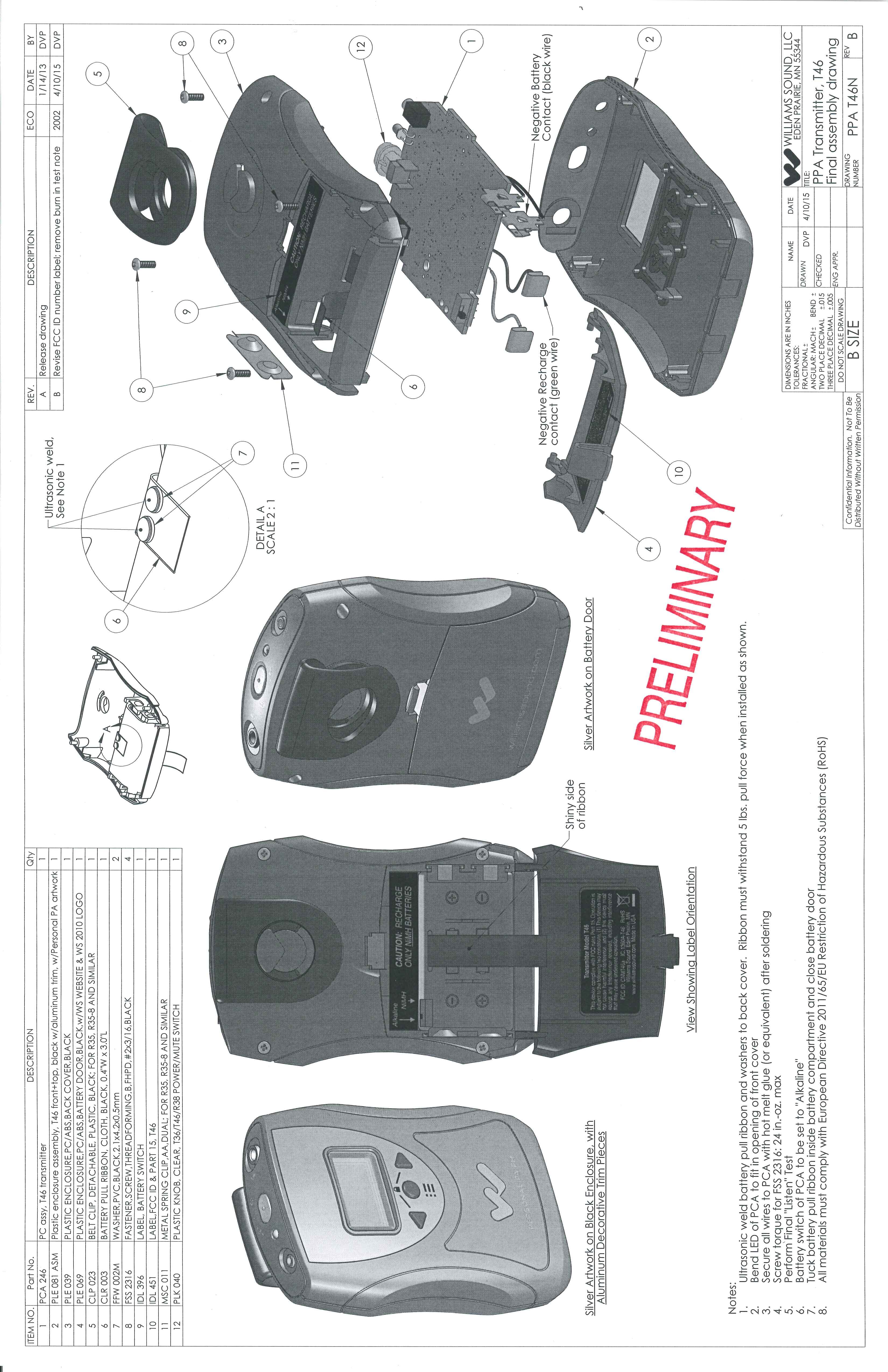
Click to zoom
Application Details
- Equipment Class
- DXT - Part 15 Low Power Transceiver, Rx Verified
- Date of Grant
- May 03, 2015
- Application Purpose
- Original Equipment
- Date of Application
- May 03, 2015
- Equipment Note
- Battery operated auditory assistance transmitter
- Frequency Range
- 75.20000000 - 76.00000000
- Company
- Williams Sound, LLC
- Country
- United States
Documents & Files
Document Text
Text extracted from the exhibit documents filed with the FCC. Open a document above to read the original.
Users Manual
PPA T46 Personal PA ® 72-76 MHz Body Pack Transmitter USER Manual MAN 175B 2 PPA T46 72-76 MHa Transmitter Contents Safety Warnings.......................................................................................................................................................................3 Hearing.Safety..................................................................................................................................................................3 Battery.Safety.and.Disposal..............................................................................................................................................3 Pacemaker.Safety.............................................................................................................................................................3 Recycling Instructions...........................................................................................................................................................3 PPA T46 Included Parts.........................................................................................................................................................3 Transmitter Applications........................................................................................................................................................3 Important Note about OLED Care.........................................................................................................................................3 System Overview.....................................................................................................................................................................4 Features...................................................................................................................................................................................4 Quick Setup.............................................................................................................................................................................4 Figure.A:.Battery.Compartment.........................................................................................................................................4 Figure.B:.Top.of.Transmitter...............................................................................................................................................4 Figure.C:.Channel/Frequency.Selection.Chart...................................................................................................................5 Figure.D:.Menu.Buttons....................................................................................................................................................5 Figure.E:.Menu.Display......................................................................................................................................................5 Figure.F:.Belt.Clip.Installation.............................................................................................................................................5 Basic Setup.............................................................................................................................................................................6 Advanced Setup...................................................................................................................................................................7-8 Dual-Preset Mode....................................................................................................................................................................8 Specifications..........................................................................................................................................................................9 Troubleshooting.....................................................................................................................................................................10 Limited Warranty...................................................................................................................................................................11 PPA T46 72-76 MHz Transmitter 3 PPA T46 72-76 MHa Transmitter Safety Warnings HeAring SAfeTy CAUTiOn! Many.Williams.Sound.receivers.are.designed.to.amplify.sounds.to. a.high.volume.level,.which.could.potentially.cause.hearing.damage. if.used.improperly..To.protect.your.hearing.and.the.hearing.of. others: 1.. Make.sure.the.volume.is.turned.down.before.putting.on.the. earphone.or.headphone—only.then.adjust.the.volume.to.a. comfortable.level.. 2.. Set.the.volume.level.at.the.minimum.setting.that.you.need.to. hear.. 3.. If.you.experience.feedback.(a.squealing.or.howling.sound),. reduce.the.volume.setting.and.move.the.microphone.away. from.the.earphone.or.headphone.. 4.. Do.not.allow.children.or.other.unauthorized.persons.access.to. this.product.. BATTery SAfeTy And diSPOSAl CAUTiOn! Williams.Sound.T46.transmitters.are.supplied.with.non-rechargeable. alkaline.batteries..Do.not.attempt.to.recharge.non-rechargeable. batteries;.they.may.explode,.release.dangerous.chemicals,.cause. burns,.or.cause.other.serious.harm.to.the.user.or.product. PACeMAker SAfeTy CAUTiOn! If.you.have.a.pacemaker.or.other.medical.device,.make.sure.that. you.are.using.the.Williams.Sound.transmitter.in.accordance.with. safety.guidelines.established.by.your.physician.or.the.pacemaker/ medical.device.manufacturer. Servicing or attempting to service this device will void the warranty Refer.servicing.to.qualified.personnel..Servicing.is.required.when. the.system.has.been.damaged.in.any.way:.if.liquid.has.been. spilled.or.objects.have.fallen.into.the.unit,.if.the.unit.has.been. exposed.to.moisture,.if.the.unit.does.not.operate.normally,.or.if.the. unit.has.been.dropped. recycling instructions Help.Williams.Sound.protect.the.environment!..Please.take.the. time.to.dispose.of.your.equipment.properly. Produc…
Text truncated - open the document above for the full version.
Users Manual
PPA T46 72-76 MHz Transmitter Instructions For Use and Care Operating Instructions 1. Open the battery compartment. Slide the battery selection switch to the correct position for the type of batteries that will be used. Use “Alkaline” for non-rechargeable batteries, “NiMH” for rechargeable NiMH batteries (only). (FIG. A) IMPORTANT: If the battery switch is not in the correct position, damage may be caused to the unit. FIG. A: Battery Compartment A311 ALKALINE/ NiMH SWITCH 2. Install the AA batteries. Be sure to observe proper polarity (+/-). Damage due to improper battery installation may void the warranty on the product. The “Power On” LED on top of the unit will flash when the batteries are getting low; you may continue to use until the unit quits operating, then replace or recharge the batteries. (FIG. A) 3. Plug in the microphone cord (sold separately) using the “Mic Jack” on top of the transmitter (FIG. B). 4. Optionally, plug in a desired audio source such as a CD or MP3 player using the “Auxiliary Input” jack (WCA 087 stereo auxiliary input cable included). If mic and auxiliary sources are used together, the audio will be mixed. If only an auxiliary source is desired, the mic can be muted. Do not remove the mic from the “Mic Jack” as the cable is also the transmitting antenna (FIG. B) 5. Turn the unit on: press and hold the “ON/OFF/MUTE” button for three seconds. The “Power On” indicator will illuminate green. (FIG. B) FIG. B: Top of Transmitter T46 TOP POWER ON/OFF, MUTE BUTTON AUXILIARY INPUT JACK MIC JACK POWER "ON", LOW BATTERY LED A310 6. Select the desired operating frequency. Refer to the following channel selection chart. Make sure the transmitter and receiver channels match. Up to eight T46’s can operate simultaneously on different channels (see R35-8 channels in chart, below). (FIG. C) FIG. C: Channel Selection Chart T46 ChLetterFreq (MHz)R35-8 Ch 1A72.11 2B72.32 3O72.63 4P72.84 5I74.75 6R75.46 7G75.77 8H75.98 9C72.5 10K72.2 11N72.4 12D72.7 13E72.9 14J75.3 15S75.6 16T75.8 17F75.5 A376 A312 MASTER VOLUME MIC MUTED SETTINGS LOCKED TRANSMIT CHANNEL BATTERY LIFE FIG. E: Main Screen 7. Change the transmitter to the desired operating frequency. Use the Menu to select any of the 17 available channels on 72-76 MHz. To access the channel setting, push the menu button until you see the channel displayed. Change the channel by pushing the left or right arrow buttons. To access additional settings, push the menu button repeatedly until you see the setting you want. If no buttons are pushed for 30 seconds, the display returns to the main screen and then shuts off to conserve battery power. (FIG. D, FIG. E) T46 FRONT LEFT ARROW BUTTON RIGHT ARROW BUTTON MENU BUTTON A309 FIG. D: Menu Buttons 8. To install the belt clip on the rear of the T46, position the belt clip on the back of transmitter. Turn the belt clip 180 ̊ left or right to secure the clip. The transmitter can now be clipped onto a belt. To remove, turn the belt clip 180 ̊ so the open end of the clip points up, and gently pull the belt clip off. (FIG. E) FIG. E: Belt Clip Installation A119 9. Position the headset microphone boom as close to the speaker’s mouth as possible without actually touching. Lapel clip microphones should be attached to a collar or lapel, as close to the speaker’s mouth as possible 10. When you pause from speaking, mute the microphone by pressing the “ON/OFF/MUTE” button once momentarily. The button will flash. The front display will also indicate the mic is muted. To unmute the mic, press the button once momentarily again. 11. When the T46 transmitter is not being used, turn the unit OFF by pressing and holding the “ON/OFF/MUTE” button for three seconds. The Power On indicator will go off. System Specifications FM Transmitter, Model T46 Battery Type: Two (2) AA 1.5 V non-rechargeable Alkaline batteries (BAT 001-2), 75 mA nominal current drain, up to 30 hours battery life, or Two (2) AA 1.5 V rechargeable NiMH batteries (BAT 026-2), 75 mA nominal current drain, up to 20 hours battery life per charge, recharges in 14–16 hours, uses CHG 3502 or CHG 3512 Charger Operating Frequencies: Selectable, 17 wideband channels, 72.1 – 75.9 MHz (channels 1-8 correspond with R35-8 receiver channels) Transmit Antenna: Integral with microphone cord (required) External/ Menu Controls: Top: Momentary push button - push and hold 3 seconds for power On/Off, push and release for microphone mute On/Off Front: Left Arrow, Menu, Right Arrow buttons for accessing/changing the transmitter settings Display: 1.25” OLED, for viewing transmitter settings Mic Input: 3.5 mm mono phone jack with electret mic bias, adjustable gain with 25 dB range (in menu) Aux Input: 2.5 mm stereo phone jack, adjustable gain with 60 dB range (in menu) Audio Compression: 1:1 (off) or 2:1 (on) ratio, selectable in menu Compatible Receivers: PFM R31, PFM R32, PFM R33, PFM R36, PPA R37, PPA R35-8, PPA R1600 Approvals/ Directives: FCC, Industry Canada, RoHS, WEEE Warranty: Lifetime Limited Warranty System Specifications Safety Information HEArInG SAFETy CAUTIOn! This product is designed to amplify sounds to a high volume. To protect your hearing and the hearing of others: 1. Make sure the unit is OFF or the volume is turned down before putting on the earphones. 2. Set volume level at the minimum setting you need to hear. 3. Do not allow children or other unauthorized persons to have access to this product. BATTEry SAFETy CAUTIOn! Do not attempt to recharge alkaline or other non- rechargeable batteries, which may explode, release dangerous chemicals, cause burns, or cause other serious harm to the user or product. MEDICAl DEvICE SAFETy CAUTIOn! Before using this product with a pacemaker or other implantable medical device, consultant your physician or the manufacturer of the device to make sure that you are using this product in accordance with their safety guidelines. recycling Instructions Help Williams Sound protect the environment! Please do not dispose o…
Text truncated - open the document above for the full version.
ID Label/Location Info
External Photo with Label and label location
Internal Photos
Williams Sound, Inc. Model T46 Internal Photos PC Board Solder side PC Board Component Side
Test Report
TEST REPORT #291014 STANDARD: FCC PART 15 SUBPART C--INTENTIONAL RADIATORS SECTION 15. 237 OPERATION IN THE BANDS 72.0–73.0 MHz, 74.6–74.8 MHz AND 75.2–76.0 MHz. EQUIPMENT TESTED: WILLIAMS SOUND, INC. FCC ID: CNMT46A MODEL: T46 TEST DATE: 29 OCTOBER 2014 INTERNATIONAL CERTIFICATION SERVICES, INC. 1100 Falcon Avenue Glencoe, MN 55336 Tele: 320-864-4444 Fax: 320-864-6611 INTERNATIONAL CERTIFICATION SERVICES, INC. Prepared for: Test agent: Test location: Prepared by: . Williams Sound, Inc. 10300 Valley View Road Eden Prairie, MN 55344 International Certification Services, Inc. 1100 Falcon Avenue Glencoe, MN 55336 Tele: 320-864-4444 Fax: 320-864-6611 International Certification Services, Inc. 1100 Falcon Avenue Glencoe, MN 55336 Tele: 320-864-4444 Fax: 320-864-6611 International Certification Services, Inc. 1100 Falcon Avenue Glencoe, MN 55336 International Certification Services represents to the client that testing is done in accordance with standard procedures applicable and that reported test results are accurate within generally accepted commercial ranges of accuracy. This report only applies to the specific samples tested under stated test conditions. It is the manufacturer’s responsibility to assure that additional production units of this model are manufactured with identical electrical and mechanical components. International Certification Services shall have no liability for any deductions, inferences or generalizations drawn by the client or others from this report. This report is the confidential property of the client. As a mutual protection to our clients, the public and ourselves, extracts from the test report shall not be reproduced except in full without our written approval. INTERNATIONAL CERTIFICATION SERVICES, INC. 1.0 TEST SUMMARY TEST REPORT: #291014 COMPANY: AGENT: International Certification Services, Inc. PHONE: 320-864-4444 TEST DATE: EQUIPMENT UNDER TEST: GENERAL TEST SUMMARY: VERIFICATION / CERTIFICATION STATUS: MODIFICATIONS NECESSARY: TESTED BY WRITTEN BY Duane R. Bagdons Duane R. Bagdons Williams Sound, Inc. 29 October, 2014 Model: T46 FM Portable battery operated auditory assistance transmitter. The testing was performed at International Certification Services, Inc. at 1100 Falcon Ave, Glencoe, MN 55336 Williams Sound, Inc. Model: T46 was found to be in compliance with the FCC Part 15 Subpart C, Section 15.237 requirements. None INTERNATIONAL CERTIFICATION SERVICES, INC. Applicable Standards 47 CFR Ch.1 (54 FR 17714, Apr 25, 1989, as amended at 57 FR 13048, Apr 15, 1992; 78 FR 34927, June 11, 2013) FCC Part 15 Radio Frequency Devices Subpart C Intentional Radiators Section 15.237 Operation in the bands 72.0–73.0 MHz, 74.6–74.8 MHz and 75.2–76.0 MHz 2.1 Referenced Standards ANSI C63.4-2003 Methods of Measurement of Radio-Noise Emissions from Low-Voltage Electrical and Electronic Equipment in the Range of 9 Khz to 40 Ghz. 2.2 Equipment Unit Tested The equipment tested was a battery powered 72 to 76 Mhz transmitter model: T46. This unit transmits on frequencies in the three allowed bands of the FCC Part 15 Subpart C section 15.237. The frequencies are operator selectable by push button switches on the front of the EUT. The 1 meter microphone cable doubles as the transmitting antenna. The EUT is powered by 2 AA (either Alkaline or NiMH) batteries. The RF output of this device is not operator adjustable. This unit is used as an Auditory Assistance Transmitting device. 2.3 Equipment and Cable Configuration See photo of the EUT test configuration setup in Attachment A 2.4 List of Test Equipment Measurement cable losses, and antenna correction factors are included in the data sheets. The Resolution BW was set at 1 Mhz and the Video BW was set at 1 Hz with a Span of 0 Hz to perform the correct average detected measurements. Calibration cycle: 2 years Test Equipment Spectrum Analyzer Preamp Biconical Antenna Log Periodic Antenna (200-1000 MHz) Horn Antenna (1-18 Ghz) Loop Antenna (10 Khz to 30 Mhz) Model Hewlett-Packard 8566B MiniCircuits ZKL-2R7 AH Systems Model SAS- 200/540 EMCO 3146 EMCO 3115 EMCO 6512 S/N 2421A00458 N/A 328 9111-3280 5697 8912-1074 Calibration Date 01/28/14 10/17/13 08/30/14 08/30/14 08/30/14 08/30/14 INTERNATIONAL CERTIFICATION SERVICES, INC. 2.5 Units of Measurement. All measurements were taken in dBuV/m with the antenna located at 3 meters distance from the EUT. Frequency measurements are recorded in Mhz. 2.6 Location of Test Site The open area test site (OATS) measurement facility used to collect the data was International Certification Services, Inc. at 1100 Falcon Ave in Glencoe, MN 55336. This site has been certified to be in spec of the normalized site attenuation per ANSI C63.4- 2003. 2.7 Measurement Procedures The antenna was placed at a distance of 3 meters from the EUT. The EUT was set on an wooden test stand in the OATS site and rotated through 360 degrees to determine the worst case EUT orientation. The transmitting antenna wire of the EUT was extended vertically above the EUT to simulate a worst case condition (Antenna fully extended). The receiving antenna was then positioned vertical and horizontal to determine which antenna polarity orientation was worst case. Then certification data was recorded at all the transmitter frequencies from the fundamental to the 10 th harmonic at an antenna height variation of from 1-4 meters. Data was recorded in three orthogonal planes to determine the worst case emissions. 2.8 Reporting Measurement Data See data sheets and plots in Attachment B. 2.9 Radiated Emissions Data The frequency and amplitude of the tuned frequency of the EUT along with the frequencies and amplitudes of the harmonics up to the 10 th harmonic are reported in the data sheets in Attachment B. This information is plotted against the limit of section 15.237 of FCC Part 15 subpart C. Both Horizontal and Vertical antenna polarities as well as antenna heights of 1 to 4 meters were observed but all maximum signal strengths occurred i…
Text truncated - open the document above for the full version.
Test Setup Photos
Williams Sound, Inc. Model T46 Testing Photos
Contact Information
Applicant
Per W. Danzl(VP of Engineering)
Test Firm
International Certification Services, Inc.Dueane Bagdons
Technical Specifications
| # | Rule Parts | Frequency Range | Power Output |
|---|---|---|---|
| 3 | 15C | 75.2 MHz - 76 MHz | - |
Other Applications from Williams Sound, LLC
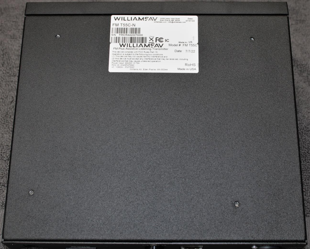
CNMFMT55C
Aug 28, 2022FM T55C
Equipment Class
GAT - Part 15 Auditory Assistance Device (Transmitter)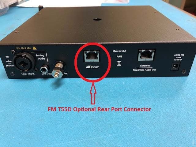
CNMFMT55
Mar 12, 2020FM T55, FM T55D
Equipment Class
GAT - Part 15 Auditory Assistance Device (Transmitter)
CNMDLT300
Nov 20, 2014Portable Conference Transmitter
Equipment Class
DSS - Part 15 Spread Spectrum Transmitter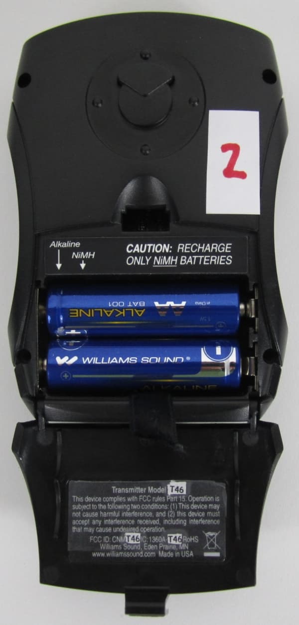
CNMT46
Oct 04, 2012Portable Hearing Assistance Transmitter
Equipment Class
GAT - Part 15 Auditory Assistance Device (Transmitter)
CNMDLT100
Jul 17, 2010Portable Conference Transmitter
Equipment Class
DSS - Part 15 Spread Spectrum Transmitter