CNMT27AUDITORY ASSISTANCE DEVICE
Williams Sound, LLC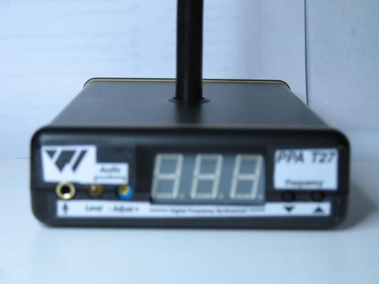
Click to zoom
Application Details
- Equipment Class
- GAT - Part 15 Auditory Assistance Device (Transmitter)
- Date of Grant
- Feb 26, 2007
- Application Purpose
- Original Equipment
- Date of Application
- Feb 22, 2007
- Equipment Note
- AUDITORY ASSISTANCE DEVICE
- Frequency Range
- 75.20000000 - 76.00000000
- Company
- Williams Sound, LLC
- Country
- United States
Documents & Files
Document Text
Text extracted from the exhibit documents filed with the FCC. Open a document above to read the original.
Users Manual
Personal PA ™ Value Pack System Wide-Band FM Wireless Listening System Transmitter Model PPA T27 Receiver Model R35 QUICKSETUPGUIDE MFRM 010A Model PPA VP ® 2 SYSTEMOVERVIEW Thank you for purchasing the Personal PA Value Pack System from Williams Sound Corporation. The PPA VP System is a Wideband FM Listening System which operates in the 72-76 MHz frequency band. Designed for hearing assistance in places of public access, the PPA VP is for those who need help overcoming background noise, reverberation, or distance from the sound source. The versatile PPA VP is easily integrated with your existing sound system or can be used with a microphone as a stand-alone system. The system has two principal parts: the T27 Transmitter and the R35 Receiver. Much like a miniature radio station, the Transmitter and microphone pick up the sounds you want to hear and broadcast them over an FM radio signal. The receivers are used to pick up the broadcast up to 500 feet away. To avoid difficulties, please read through these instructions as you begin to use the system. Then save the manual for questions that arise as you continue to use your PERSONAL PA Value Pack System. If you have any problems with this Williams Sound product, don’t hesitate to call us toll-free at 1-800-843-3544. Sound System Amplifier Loudspeakers Microphones Line-Level Output R35 Wide-band Receivers w/Earphones Line-Level Input T27 Transmitter FIG. 1: OVERALLSYSTEMDIAGRAM ® 3 SETTINGUP THEPPA VP þ STEP1: SELECTLOCATION Position the PPA T27 transmitter near the sound system or mixer from which it will receive audio. þ STEP2: INSTALL THEANTENNA Gently thread the ANT021 rubber duckie antenna onto the stud recessed in the hole on the top of the transmitter. Note: The antenna output on the back of the unit has been defeated, as specified by FCC Rules. To use a remote antenna, contact your dealer or Williams Sound. þ STEP3: CONNECTTHEPOWER Locate the power supply cord equipped with the 5-pin DIN connector, then plug the connector into the “Power In” jack located in the back of the T27. Plug in the power supply into the AC outlet. On power up, the number “8” will scroll across the T27 display 3 times while the system initializes. The system will then display the default system frequency (72.9 MHz) orthe last selected frequency set by the user . þ STEP4: SELECT THEFREQUENCY The T27 has 17 available channels in the 72-76 MHz bandwidth. By default, the T27 frequency is set to 72.900 MHz. To change the frequency on the T27, press and release the down “ ˇ “ or up “ ˆ “ frequency selector button until the desired frequency is displayed. After 3 seconds of no activity, the frequency selection will be set. Check to make sure the receiver being used is operating on the same frequency as the trans- mitter! NOTE: You can LOCKthis selection to prevent others from accidently changing the frequency. T o LOCKthe frequency you have selected, press and hold bothdown “ ˇ ” and up “ ˆ ” frequency selector buttons for 3 seconds until the word “Loc” appears on the display. The frequency is now locked. Should the user press the frequency selector button while in “Lock” mode, the word “Loc” will be displayed for 2 seconds. To UNLOCKthe frequency selected, press and hold bothdown “ ˇ ” and up “ ˆ ” frequency selector buttons for 3 seconds until the transmitter displays ”Un” then “Loc” on the display . The frequency is now unlocked. The user is now free to change the frequeny channels on the T27 as needed. FIG 2: Features & Controls Front View Rear View 1. Mic input jack, 3.5 mm 2. Audio Level Indicator 3. Audio Level Control 4. Frequency Display (LED) 5. Frequency Selector, Lock/Unlock Control 6. Power Input jack, 12VAC 7 . Antenna Connector, 7 5 Ohms 8. Audio input jack, RCA-type ( Line Level, Unbalanced) 123 4 5 6 7 8 ® 4 þ ST EP 5: CO NNECT THE AU DIO SO URCE On the back of the T27, an RCA-type “Audio In” jack is available for connecting a line-level, unbal- anced audio source. On the front of the T27, a 3.5mm “Mic Input” jack is available to connect a Williams Sound electret microphone. Connect the desired audio source to the T27 transmitter and pro- ceed to Step 6. þ STEP6: ADJUST THE AUDIOLEVEL With the audio source playing, use a small screwdriver or tuning wand to rotate the “Adjust” control on the front of the T27 1) clockwiseto increasethe audio level; or 2) counterclockwiseto decreasethe audio level. Refer to the LED audio “Level” indicator on the front of the T27 as you make your adjust- ments: Audio Level LEDIndicator 1.) Never On = Audio source is TOO LOW. 2.) Blinks occassionally = Audio source is OPTIMAL. 3.) Always on = Audio source is TOO HIGH. þ STEP7: LISTEN WITH ANFM RECEIVER IMPORTANT : The FM receiver being used with the T27 transmitter will need to be on the same frequency and bandwidth as the transmitter. To retune the FM receiver, follow the tuning instruc- tions included with that unit. For R35 tuning instructions, see page 6. Install the receiver batteries, plug in the earphone, turn on the receiver and walk around the listening area. The signal should be clear and quite loud when the volume is turned up. See pages 5-7 for detailed R35 receiver instructions. FCC Warning Statement Changes or modifications not expressly approved by the party responsible for compliance could void the user's authority to operate the equipment. ® 5 PPA R35 RECEIVERINSTRUCTIONS The PPA R35 is a single-channel receiver operating on the 72-76 MHz bandwidth. It features volume on/off control, LED power and low battery indicator, and an earphone jack. Instructions: BATTERYINSTALLATION Install two (2) AAalkaline or NiMH rechar geable batteries. Open the battery compartment by lifting the tab on the back of the receiver with a finger. To remove depleted batteries, pull up on the fabric strip. IMPORTANT: If Alkaline (non-rechargeable) batteries are being installed, slide the battery selection switch above the battery compartment to the “Alkaline” position. If installin…
Text truncated - open the document above for the full version.
External Photos
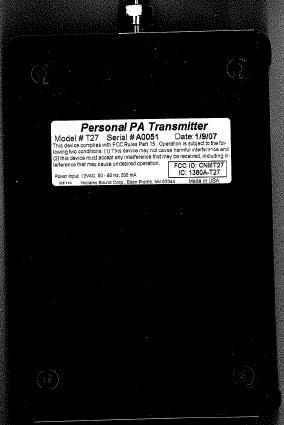
FCC ID: CNMT27 Project: 351AUT7
Internal Photos
FCC ID: CNMT27 Project: 351AUT7
Test Report
FCC PART 15.237 Auditory Assistance Device Low Power Unlicensed Intentional Radiator TEST REPORT Applicant Williams Sound Corporation Address 10321 West 70th Street Eden Prairie, MN 55344 USA FCC ID CNMT27 Model Number T27 Product Description Audio Assistance Device Date Sample Received February 3, 2007 Date Tested February 7, 2007 Tested By Nam Nguyen Approved By Mario de Aranzeta Report Number 351AUT7TestRepot.PDF Test Results PASS FAIL THE ATTACHED REPORT SHALL NOT BE REPRODUCED EXCEPT IN FULL WITHOUT THE WRITTEN APPROVAL OF TIMCO ENGINEERING, INC. 849 NW State Road 45 Newberry, FL 32669 USA Phone: 888.472.2424 or 352.472.5500 Fax: 352.472.2030 Email: [email protected] Website: www.timcoengr.com Certificate # 0955-01 Applicant: Williams Sound Corporation FCC ID: CNMT27 Report:W:\W\WSC\351AUT7\351AUT7TestReport.doc Page 2 of 31 TABLE OF CONTENT STATEMENT OF COMPLIANCE.................................................................................. 3 REPORT SUMMARY................................................................................................... 4 TEST SYSTEM SETUP ............................................................................................... 4 DUT DESCRIPTION ................................................................................................... 5 EMC EQUIPMENT LIST ............................................................................................. 6 TEST PROCEDURES ................................................................................................. 7 ANTENNA REQUIREEMENT ...................................................................................... 9 RADIATION INTERFERENCE ................................................................................... 10 MODULATION CHARACTERISTICS.......................................................................... 18 OCCUPIED BANDWIDTH ......................................................................................... 20 RADIATED SPURIOUS EMISSIONS INTO ADJACENT RESTRICTED BAND............... 22 POWER LINE CONDUCTED INTERFERENCE........................................................... 30 Applicant: Williams Sound Corporation FCC ID: CNMT27 Report:W:\W\WSC\351AUT7\351AUT7TestReport.doc Page 3 of 31 STATEMENT OF COMPLIANCE Certificate #0955-01 This equipment has been tested in accordance with the standards identified in the referenced test report. To the best of my knowledge and belief, these tests were performed using the measurement procedures described in this report and demonstrate that the equipment does comply with the appropriate standards. All Timco instrumentation and accessories used to test products for compliance to the indicated standards are calibrated regularly in accordance with ISO 17025 requirements. I attest that the necessary measurements were made by me or under my supervision, at TIMCO ENGINEERING, INC. located at 849 N.W. State Road 45, Newberry, Florida 32669 USA. Authorized by: Mario de Aranzeta Signature: <on file> Function: Engineer Date: February 20, 2007 Tested by: Nam Nguyen Date: February 16, 2007 Applicant: Williams Sound Corporation FCC ID: CNMT27 Report:W:\W\WSC\351AUT7\351AUT7TestReport.doc Page 4 of 31 REPORT SUMMARY Purpose of Report To demonstrate the DUT in compliance with FCC CFR 47 Part 15.237 requirements for auditory assistance device. Disclaimer The test results relate only to the items tested. Applicable Standards FCC CFR 47, Pt 15.237, ANSI C63.4-2003 Related Report Digital portion is in compliance with Pt15.109, Pt 15.107 requirements in 2755BUT6TestReport TEST ENVIRONMENT Test Facility Timco Engineering Inc 849 NW State Road 45 Newberry, FL 32669 USA Laboratory Condition Temperature: 26ºC, Humidity: 50% TEST SYSTEM SETUP Certified System The EUT was tested with the microphone and/or accessories provided by the applicant, which includes a S/N: 086 microphone and a microphone simulator. Modification to DUT No modification was made to ensure the DUT in compliance with regulatory requirements Test Exercise The DUT was placed in continuous transmit mode of operation Cable N/A Supporting Equipment The device is a stand-alone device operated by installed manufacturer software specified in operation manual. Applicant: Williams Sound Corporation FCC ID: CNMT27 Report:W:\W\WSC\351AUT7\351AUT7TestReport.doc Page 5 of 31 DUT DESCRIPTION Manufacturer Williams Sound Corporation DUT Auditory Assistance Device FCC ID CNMT27 Model Number T27 Serial Number N/A Trade Name Hearing Helper Operating Frequency 72.1 ~ 75.9 MHz No. of Channels Selectable 17 channels, up and down push button Max. Output Power N/A Modulation Wideband FM Mic Connector 3.5 mm mono phone jack DUT Power Source 12VAC adaptor Test Item Prototype Pre-Production Production Type of Equipment Fixed Mobile Portable Antenna Connector Antenna Specification A. M/N: 021 B. M/N: 024 C. M/N: 025 D. M/N: 005 Applicant: Williams Sound Corporation FCC ID: CNMT27 Report:W:\W\WSC\351AUT7\351AUT7TestReport.doc Page 6 of 31 EMC EQUIPMENT LIST Device Manufacturer Model Serial Number Cal/Char Date Due Date 3/10-Meter OATS TEI N/A N/A Listed 3/27/04 3/26/07 3-Meter OATS TEI N/A N/A Listed 1/11/06 1/10/09 Antenna: Biconnical Eaton 94455-1 1057 CAL 12/12/05 12/12/07 Antenna: Biconnical Electro- Metrics BIA-25 1171 CAL 4/29/05 4/29/07 Analyzer Blue Tower Quasi-Peak Adapter HP 85650A 2811A01279 CAL 4/13/05 4/13/07 Analyzer Blue Tower RF Preselector HP 85685A 2926A00983 CAL 9/5/05 9/5/07 Analyzer Blue Tower Spectrum Analyzer HP 8568B 2928A04729 2848A18049 CAL 4/13/05 4/13/07 LISN Electro- Metrics ANS-25/2 2604 CAL 8/27/06 8/27/08 LISN Electro- Metrics EM-7820 2682 CAL 4/28/05 4/28/07 Antenna: Log-Periodic Eaton 96005 1243 CAL 12/14/05 12/14/07 Applicant: Williams Sound Corporation FCC ID: CNMT27 Report:W:\W\WSC\351AUT7\351AUT7TestReport.doc Page 7 of 31 TEST PROCEDURES Power Line Conducted Interference The measurements were made in accordance with ANSI C63.4-2003 “Methods and Measureme…
Text truncated - open the document above for the full version.
Contact Information
Applicant
Per W. Danzl(VP of Engineering)
Test Firm
Timco Engineering, Inc.Sid Sanders
Technical Specifications
| # | Rule Parts | Frequency Range | Power Output |
|---|---|---|---|
| 3 | 15.237 | 75.2 MHz - 76 MHz | - |
Other Applications from Williams Sound, LLC
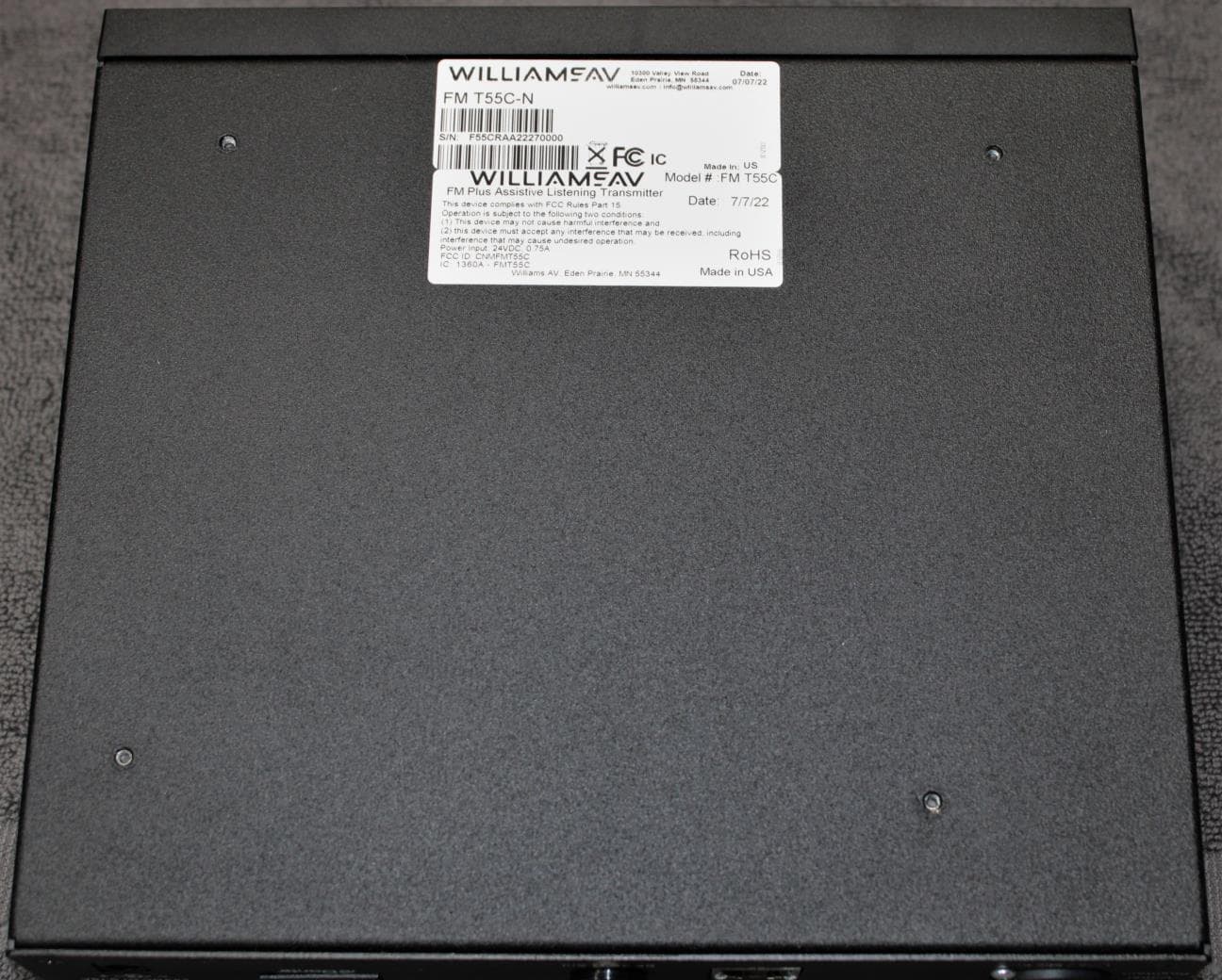
CNMFMT55C
Aug 28, 2022FM T55C
Equipment Class
GAT - Part 15 Auditory Assistance Device (Transmitter)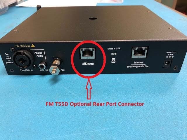
CNMFMT55
Mar 12, 2020FM T55, FM T55D
Equipment Class
GAT - Part 15 Auditory Assistance Device (Transmitter)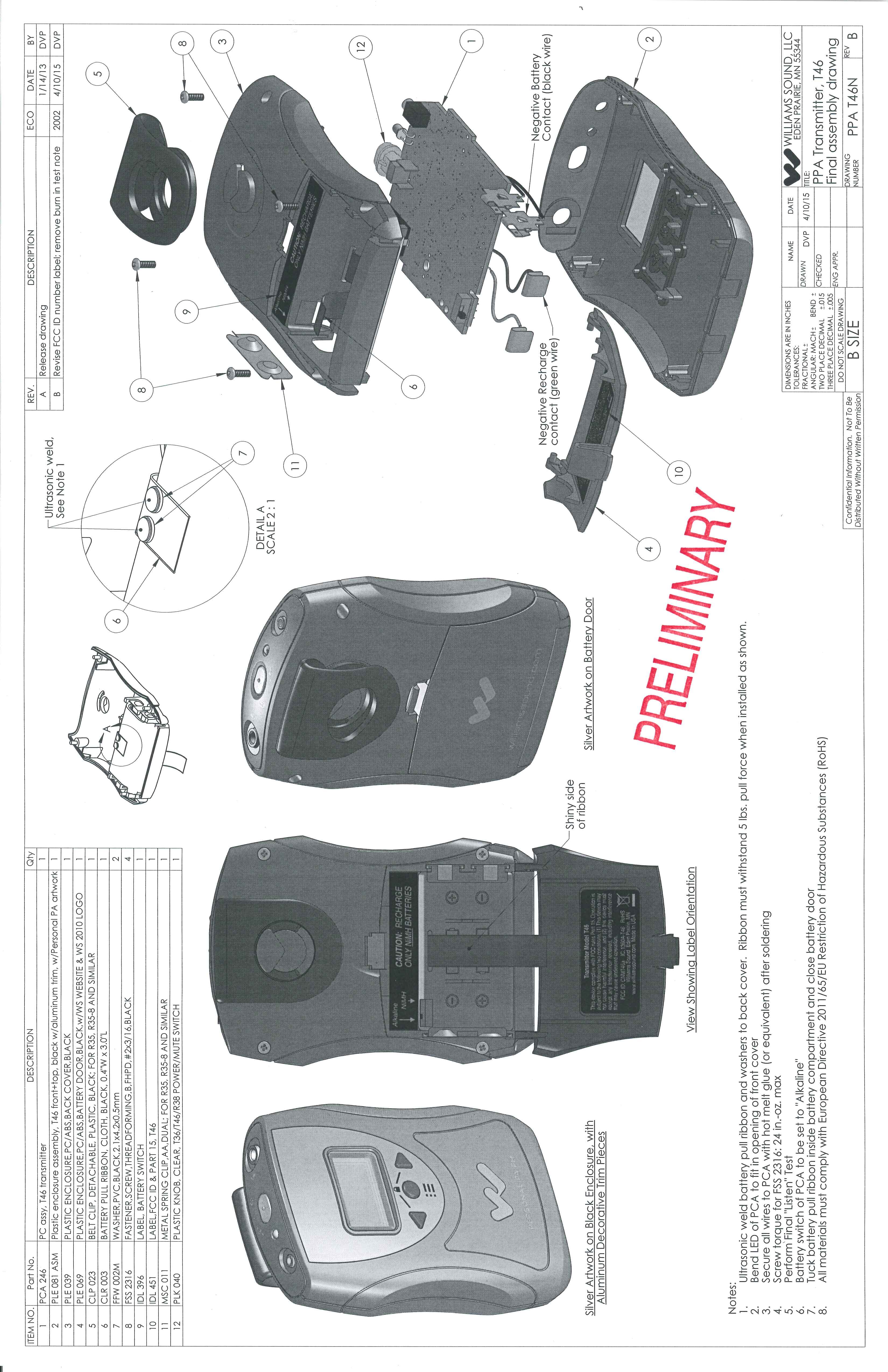
CNMT46A
May 03, 2015Battery operated auditory assistance transmitter
Equipment Class
DXT - Part 15 Low Power Transceiver, Rx Verified
CNMDLT300
Nov 20, 2014Portable Conference Transmitter
Equipment Class
DSS - Part 15 Spread Spectrum Transmitter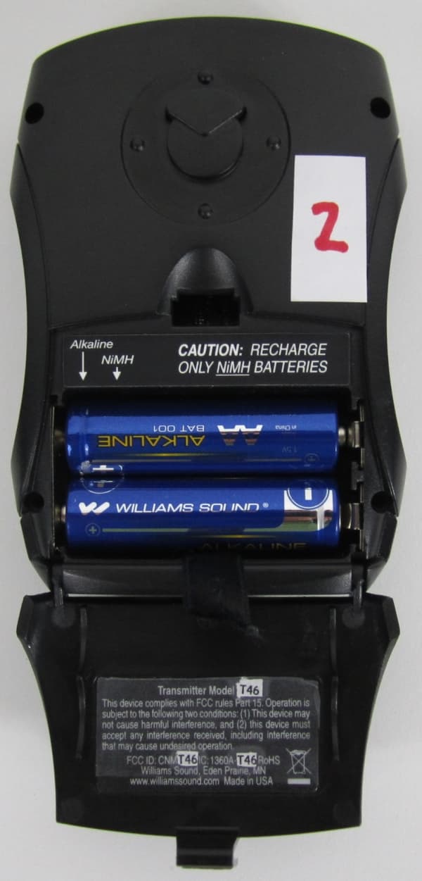
CNMT46
Oct 04, 2012Portable Hearing Assistance Transmitter
Equipment Class
GAT - Part 15 Auditory Assistance Device (Transmitter)