CNMT32AUDITORY ASSISTANCE DEVICE
Williams Sound, LLC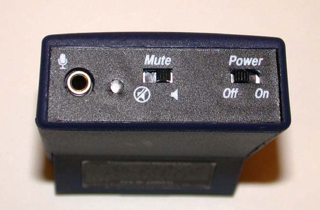
Click to zoom
Application Details
- Equipment Class
- GAT - Part 15 Auditory Assistance Device (Transmitter)
- Date of Grant
- Oct 30, 2006
- Application Purpose
- Original Equipment
- Date of Application
- Oct 30, 2006
- Equipment Note
- AUDITORY ASSISTANCE DEVICE
- Frequency Range
- 75.30000000 - 75.90000000
- Company
- Williams Sound, LLC
- Country
- United States
Documents & Files
Document Text
Text extracted from the exhibit documents filed with the FCC. Open a document above to read the original.
Users Manual
MAN 126B ©2006 Williams Sound Corp ® 2 ® 3 ® ® 10321 West 70th St., Eden Prairie, MN 55344 U.S.A. 800.843.3544 | 952.943.2252 | FAX: 952.943.2174 www.williamssound.com Product Recycling: Please do NOT dispose of your Williams Sound equipment in the household trash. Please take the equipment to a electronics recy- cling center; OR, return the product to the factory for proper disposal. Battery Recycling: Please do NOT dispose of used batteries in the household trash. Please take the batteries to a retail or community collection point for recycling. 9/19/06 OPERATINGINSTRUCTIONS 1. Install two (2) AA batteries. If you’re using rechargeable batteries, they must be charged before using. 2. Plug the microphone cord into the “Mic” jack on top of the transmitter. 3. Place the transmitter in the belt clip case provided. 4. Slide the Power Switch on top of the transmitter to “On.” The Power ON LED indicator should illuminate Red. 5. The microphone should be placed as close to the speaker’s mouth as is practical. For lapel mics, attach the microphone to a collar, lapel, or tie. 6. When you are ready to speak, turn the Mic Mute Switch (speaker icon) to the “On” position. When you are done speaking, mute the mic by turning the Mute Switch to the “Off” position (speaker icon with line through it). The transmitter can be placed in a pants pocket, or clipped onto a belt or waistband. Important: To conserve battery life, remember to turn the trans- mitter OFF when it is not in use. Note On The Transmitter Antenna: The microphone cord is the trans- mitting antenna. Do not bunch up the cord or wrap it around the Thank you for purchasing the PFM T32 transmitter from Williams Sound. The T32 is designed to operate with a wideband FM, 72–76 MHz receiver. For more information on available receivers, contact Williams Sound at 800-843-3544. How the system works:The PFM T32 transmitter uses a microphone (not included) to pick up the desired sound source. The speaker talks into the micro- phone and the T32 transmitter broadcasts the message over an FM radio signal. Listeners wear FM receivers equipped with headphones to pickup the broadcast and hear the speaker’s message. Hearing Helper ™ Transmitter, Model PFM T32 Instructions For Use and Care PACEMAKERSAFETY 1. Beforeusing this product with a pacemaker or other medical device, consult your physician or the manufacturer of your pacemaker or other medical device. 2. If you have a pacemaker or other medical device, make sure that you are using this product in accordance with safety guidelines established by your physician or the pace- maker manufacturer. BATTERYSAFETY& DISPOSAL Do not attempt to recharge dis- posable batteries, which may explode, release dangerous chem- icals, cause burns, or other seri- ous harm to the user or product. RECYCLINGINSTRUCTIONS Help Williams Sound protect the envi- ronment! Please take the time to dis- pose of your equipment properly. CAUTION! CAUTION! transmitter. For maximum range, the cord should hang as straight as possible. BATTERYINSTRUCTIONS This transmitter can use dispos- able AA batteries (alkaline or NiMH) or a Williams Sound rechargeable battery (BAT 026). We recommend using BAT 026 AA NiMH or BAT 001 AA Alkaline batteries. BAT 026 bat- teries will last about 20 hours per charge when used with Williams Sound transmitters. BAT001 bat- teries will last approx. 30 hours when used with Williams Sound transmitters. Batteries from other suppliers may provide different operating life. Low Battery Indicator The power ON LED indicator will flash to indicate low battery. A soft pulsing sound may be heard on the receiver(s) being used. EXPECTEDBATTERYLIFE Alkaline batteries (BAT 001) : 30 hrs. Rechargeable NiMH Batteries (BAT 026) : 20 hrs. per charge. Min. 14 hour recharge time. INSTALLING ANDREPLACING BATTERIES 1. Open the battery compartment by lifting the tab on the bottom of the transmitter with a coin or finger. 2. To remove depleted batteries, pull up on the fabric strip. 3. To install new batteries, press them into place over the fabric strip. Be sure to observe proper polarity (+/–). 4. Close the lid. 5. When the sound becomes weak or distorted, replace or recharge batteries. If recharg- ing, use the Williams Sound CHG 200 Battery Charger. FIG 1: PFM T32 Top View FIG 2: T32 Battery Compartment Dimensions:3-5/8" L x 2-3/8" W x 7/8" H (92.1 mm x 60.3 mm x 22.2 mm) Weight:4.4 oz (125 g) with battery Color:Royal blue, shatter-resistant polypropylene Battery Type:Two (2) AA 1.5 V non-rechargeable Alkaline batteries (BAT 001), 70 mA nominal current drain, 30 hours approx. life (OR) Two (2) AA 1.5 V NiMH rechargeable batteries (BAT 026), 70 mA nominal current drain, 20 hours per charge approx., recharges in 14–16 hours, uses CHG 200 or CHG 1600 Charger Operating Freq’s:Selectable, 16 channels, 72.1 – 75.9 MHz, internal rotary switch Stability:±.005%, frequency synthesized, crystal reference, PLL Modulation:Wide-band FM, 75 kHz pk, 75 μ S pre-emphasis RF Output:8000 μ V/m at 30 m, max., 40 mW typical Freq Response:200 to 10 kHz, + 3 dB at 1% max. THD Signal-to-Noise Ratio: 55 - 60 dB, with R31 or R32 Receiver Microphone Gain Control:45 dB maximum, 18 dB minimum range Transmit Antenna:Integral with 39" microphone cord Microphone:Electret type, 39" cord, 3.5 mm mono phone plug Controls:On/Off switch, slide-type; Microphone Mute Switch, slide-type; Compression Selector 1:1 or 2:1 with internal selectable jumper Mic Connector:3.5 mm mono phone jack Compatible Receivers:PPAR35, PFM R31, PFM R32 Approvals:FCC, Industry Canada, RoHS, WEEE Warranty:5 years, parts and labor (90 days on accessories) Note: FCC regulations, section 15.21, requires the user to comply with the rules of transmitter operation. Any changes or modifications made by the user not expressly approved for compliance may result in the loss of all privi- leges and authority to operate the equipment. SYSTEMSPECIFICATIONS HEARINGHELPER ™ PFM T32 TRANSMITTER MAN 126B ©2006 Wil…
Text truncated - open the document above for the full version.
External Photos
Applicant: Williams Sound Corporation FCC ID: CNMT32 Report: DUT External photos Page 1 of 1
ID Label/Location Info
Proposed Label Location – Back of the DUT Proposed ID Label location – Back of the DUT
Internal Photos
Applicant: Williams Sound Corporation FCC ID: CNMT32 Report: DUT Internal photos Page 1 of 1
Operational Description
T32 Circuit Description/ Theory of Operation Date: 9/25/06 Revision: A General. The T32 transmitter is designed for hearing assistance and language translation functions. It is designed to operate in the 72-76 MHz band under part 15 of the FCC regulations and Industry Canada regulations. It is a portable transmitter designed to work with two AA size, alkaline or rechargeable batteries. It is sold with one of four different lapel or head worn microphones. The microphone cordage is also used as the transmitter antenna. The entire circuit board assembly is housed inside a polypropylene case. Reference Documents: Schematic P/N: SCH 195 User Manual P/N: MAN126A Microphone/ Antenna drawings: MIC 054, MIC 090, MIC 086, MIC 044 2P FCC label drawing P/N: IDL 373 T32 Block Diagram: List of general characteristics: User Controls, Indicators, and Connectors. 1. Power ON/OFF switch. This slide switch is located on the bezel. As indicated, it turns the transmitter battery power off and on. 2. Channel Selection switch. This is a 16 position binary rotary switch located inside the transmitter case, reached by opening up the back. It selects one of 16 RF channels for the transmitter to operate on. 3. Mute switch. This circuit reduces the audio output of the transmitter by 45 dB. It is located on the bezel. 4. Microphone jack. This is where the microphone plugs in. It is on the bezel. 5. Power/Low Battery indicator. This LED is located next to the microphone jack on the bezel. Solid “ON” indicates power on and blinking indicates a low battery condition. 6. Compression Jumper. This jumper and its associated 3 pins are located inside the transmitter case near the front bezel. The jumper positioned on the two 1:1 pins is for normal linear audio output. The jumper positioned on the 2:1 pins gives an audio output with a2: 1 compression ratio. The effect of 2:1 compression is the audio gain is raised higher at low microphone input levels than with a 1:1 ratio. At higher microphone input levels the gain is restored to the same level as the 1:1 ratio. Circuit functions: 1. Audio circuit. This circuit accepts audio signals from the microphone jack and amplifies it to the level needed for modulation of the transmitter. Potentiometer R54 adjusts the microphone gain to accommodate several different microphone sensitivities. A 75u second pre-emphasis is added by a second amplifier. Audio limiting to prevent over modulation is done in two stages. The first stage senses the audio level and clamps it to a preset level while the second stage is a hard diode limiter or clamp circuit. The final modulation level is preset by adjusting the trimmer potentiometer R46 while the audio level is at the limiter level. This will ensure the transmitter will not over modulate. 2. Modulator circuit. This circuit combines the output of the audio circuit with the PLL loop filter output and applies them to the VCO in such a way as to provide good, clear, low distortion FM transmission. 3. VCO circuit. This circuit creates the RF output signal. It is controlled by the PLL and modulator circuits. 4. RF power amplifier circuit. This circuit provides a controlled amplification of the RF from the VCO, provides necessary harmonic filtering and matching to the RF antenna (the microphone cord). 5. PLL. The phase locked loop integrated circuit keeps the VCO on frequency. 6. Microcontroller. The microprocessor is programmed to read the channel switch and send the correct codes to the PLL chip to set it up correctly. 7. SMPS. The switched mode power supply converts the battery supply voltage to a stable, efficient 5VDC to operate the various functions of the transmitter. 8. Reverse Battery Protection Circuit. This circuit protects the transmitter when the batteries are installed backwards. 9. Linear Voltage Regulator. This circuit provides a low noise, well regulated 4.5 VDC to power various transmitter circuits. It gets its supply from the SMPS. Part of its function is to remove the high frequency ripple form the SMPS supply. 10. Low battery Monitor. Battery voltage is detected by the microcontroller which blinks the power LED when it gets below 2.0 volts. Detailed Circuit Descriptions: This section describes the details of how each individual circuit works, the inputs required, and the outputs it generates. Please reference SCH 195 to follow the explanation. SMPS. Input: 2.0VDC to 3.2VDC battery supply voltage. Current draw is up to 60 mA at 3.2VDC, 130 mA at 2.0VDC. Output: regulated 5.0 VDC at 1.6 to 3.2 VDC input Description: This circuit accepts the battery current from Q10, the reverse battery protection circuit. The NCP1400 DC to DC converter is a standard boost regulator operating at 180 kHz. Pin 5 is periodically grounded through an internal switch, charging the flyback choke L4. When the switch opens, the field in L4 collapses charging C64 through the top diode in D6. D6 is a schottkey diode (BAT54s) for improved efficiency. The output voltage from C64 is connected back to pins 1 and 2. Pin 1 is the chip enable pin. If the voltage at pin 1 is less than 0.3V the chip will not start. The chip is enabled if the voltage here is greater than 0.9VDC. Pin 2 is the output voltage monitor (feedback pin) and also the power supply pin for the device. If this circuit is operating properly, there should be 5VDC on TP9 for any supply voltage form 2.0VDC to 3.2VDC. Linear Voltage Regulator: Input: 5.0VDC from the SMPS. Output: 4.5VDC at TP9. Description: This circuit is a typical low noise, low dropout voltage regulator. It is comprised of C61, C62, C57, R61, C63, and IC5. C62 is the bypass cap and serves to reduce the output noise, critical in this application. C61 is the input capacitor, and C63 is the output capacitor. This device is protected internally against short circuits and should not be damaged by them. If this circuit is operating properly there should be solid 4.5VDC on TP9. VCO: Inputs: +4.5VDC from the linear Regulator. Steering voltage fo…
Text truncated - open the document above for the full version.
Test Report
FCC PART 15.237 Auditory Assistance Device Low Power Unlicensed Intentional Radiator TEST REPORT Applicant Williams Sound Corporation Address 10321 West 70th Street Eden Prairie, MN 55344 USA FCC ID CNMT32 Model Number T32 Product Description Audio Assistance Device Date Sample Received September 28, 2006 Date Tested October 5, 2006 Tested By Nam Nguyen Approved By Mario de Aranzeta Report Number 2755AUT6TestRepot Test Results PASS FAIL THE ATTACHED REPORT SHALL NOT BE REPRODUCED EXCEPT IN FULL WITHOUT THE WRITTEN APPROVAL OF TIMCO ENGINEERING, INC. 849 NW State Road 45 Newberry, FL 32669 USA Phone: 888.472.2424 or 352.472.5500 Fax: 352.472.2030 Email: [email protected] Website: www.timcoengr.com Certificate # 0955-01 Applicant: Williams Sound Corporation FCC ID: CNMT32 Report:V:\W\WSC\2755AUT6\2755AUT6TestReport.doc Page 2 of 22 TABLE OF CONTENT STATEMENT OF COMPLIANCE.................................................................................. 3 REPORT SUMMARY................................................................................................... 4 TEST SYSTEM SETUP ............................................................................................... 4 DUT DESCRIPTION ................................................................................................... 5 EMC EQUIPMENT LIST ............................................................................................. 6 TEST PROCEDURES ................................................................................................. 7 RADIATION INTERFERENCE ..................................................................................... 9 MODULATION CHARACTERISTICS.......................................................................... 12 OCCUPIED BANDWIDTH ......................................................................................... 14 RADIATED SPURIOUS EMISSIONS INTO ADJACENT RESTRICTED BAND............... 15 POWER LINE CONDUCTED INTERFERENCE........................................................... 22 Applicant: Williams Sound Corporation FCC ID: CNMT32 Report:V:\W\WSC\2755AUT6\2755AUT6TestReport.doc Page 3 of 22 STATEMENT OF COMPLIANCE Certificate #0955-01 This equipment has been tested in accordance with the standards identified in the referenced test report. To the best of my knowledge and belief, these tests were performed using the measurement procedures described in this report and demonstrate that the equipment does comply with the appropriate standards. I attest that the necessary measurements were made by me or under my supervision, at TIMCO ENGINEERING, INC. located at 849 N.W. State Road 45, Newberry, Florida 32669 USA. Authorized by: Mario de Aranzeta Signature: <on file> Function: Engineer Date: October 12, 2006 Tested by: Nam Nguyen Signature: on file Date: October 5, 2006 Applicant: Williams Sound Corporation FCC ID: CNMT32 Report:V:\W\WSC\2755AUT6\2755AUT6TestReport.doc Page 4 of 22 REPORT SUMMARY Purpose of Report To demonstrate the DUT in compliance with FCC CFR 47 Part 15.237 requirements for auditory assistance device. Disclaimer The test results relate only to the items tested. Applicable Standards FCC CFR 47, Pt 15.237, ANSI C63.4-2003 Related Report Digital portion is in compliance with Pt15.109, Pt 15.107 requirements in 2755BUT6TestReport TEST ENVIRONMENT Test Facility Timco Engineering Inc 849 NW State Road 45 Newberry, FL 32669 USA Laboratory Condition Temperature: 26ºC, Humidity: 50% TEST SYSTEM SETUP Certified System The EUT was tested with the microphone and/or accessories provided by the applicant, which includes a S/N: 086 microphone and a microphone simulator. Modification to DUT No modification was made to ensure the DUT in compliance with regulatory requirements Test Exercise The DUT was placed in continuous transmit mode of operation Cable N/A Supporting Equipment The device is a stand-alone device operated by installed manufacturer software specified in operation manual. Applicant: Williams Sound Corporation FCC ID: CNMT32 Report:V:\W\WSC\2755AUT6\2755AUT6TestReport.doc Page 5 of 22 DUT DESCRIPTION Manufacturer Williams Sound Corporation DUT Auditory Assistance Device FCC ID CNMT32 Model Number T32 Serial Number N/A Trade Name Hearing Helper Operating Frequency 72.1 ~ 75.9 MHz No. of Channels Selectable 16 channels, internal rotary switch Max. Output Power N/A Modulation Wideband FM Mic Connector 3.5 mm mono phone jack DUT Power Source Battery Operated Exclusively Test Item Prototype Pre-Production Production Type of Equipment Fixed Mobile Portable Antenna Specification Integral with 39” microphone cord Applicant: Williams Sound Corporation FCC ID: CNMT32 Report:V:\W\WSC\2755AUT6\2755AUT6TestReport.doc Page 6 of 22 EMC EQUIPMENT LIST Device Manufacturer Model Serial Number Cal/Char Date Due Date 3/10-Meter OATS TEI N/A N/A Listed 3/27/04 3/26/07 3-Meter OATS TEI N/A N/A Listed 1/11/06 1/10/09 Antenna: Biconnical Eaton 94455-1 1057 CAL 12/12/05 12/12/07 Antenna: Biconnical Electro- Metrics BIA-25 1171 CAL 4/29/05 4/29/07 Analyzer Blue Tower Quasi-Peak Adapter HP 85650A 2811A01279 CAL 4/13/05 4/13/07 Analyzer Blue Tower RF Preselector HP 85685A 2926A00983 CAL 9/5/05 9/5/07 Analyzer Blue Tower Spectrum Analyzer HP 8568B 2928A04729 2848A18049 CAL 4/13/05 4/13/07 LISN Electro- Metrics ANS-25/2 2604 CAL 8/27/06 8/27/08 LISN Electro- Metrics EM-7820 2682 CAL 4/28/05 4/28/07 Antenna: Log-Periodic Eaton 96005 1243 CAL 12/14/05 12/14/07 Applicant: Williams Sound Corporation FCC ID: CNMT32 Report:V:\W\WSC\2755AUT6\2755AUT6TestReport.doc Page 7 of 22 TEST PROCEDURES Power Line Conducted Interference The procedure used was ANSI STANDARD C63.4-2003 using a 50uH LISN. The spectrum was scanned from .15 to 30 MHz. The bandwidth of the spectrum analyzer was 10 kHz with an appropriate sweep speed. Radiation Interference The test procedure used was ANSI STANDARD C63.4-2003 using an Agilent spectrum analyzer with a pre-selector. In the frequency range 10 kHz to…
Text truncated - open the document above for the full version.
Contact Information
Applicant
Per W. Danzl(VP of Engineering)
Test Firm
Timco Engineering, Inc.Sid Sanders
Technical Specifications
| # | Rule Parts | Frequency Range | Power Output |
|---|---|---|---|
| 3 | 15.237 | 75.3 MHz - 75.9 MHz | - |
Other Applications from Williams Sound, LLC
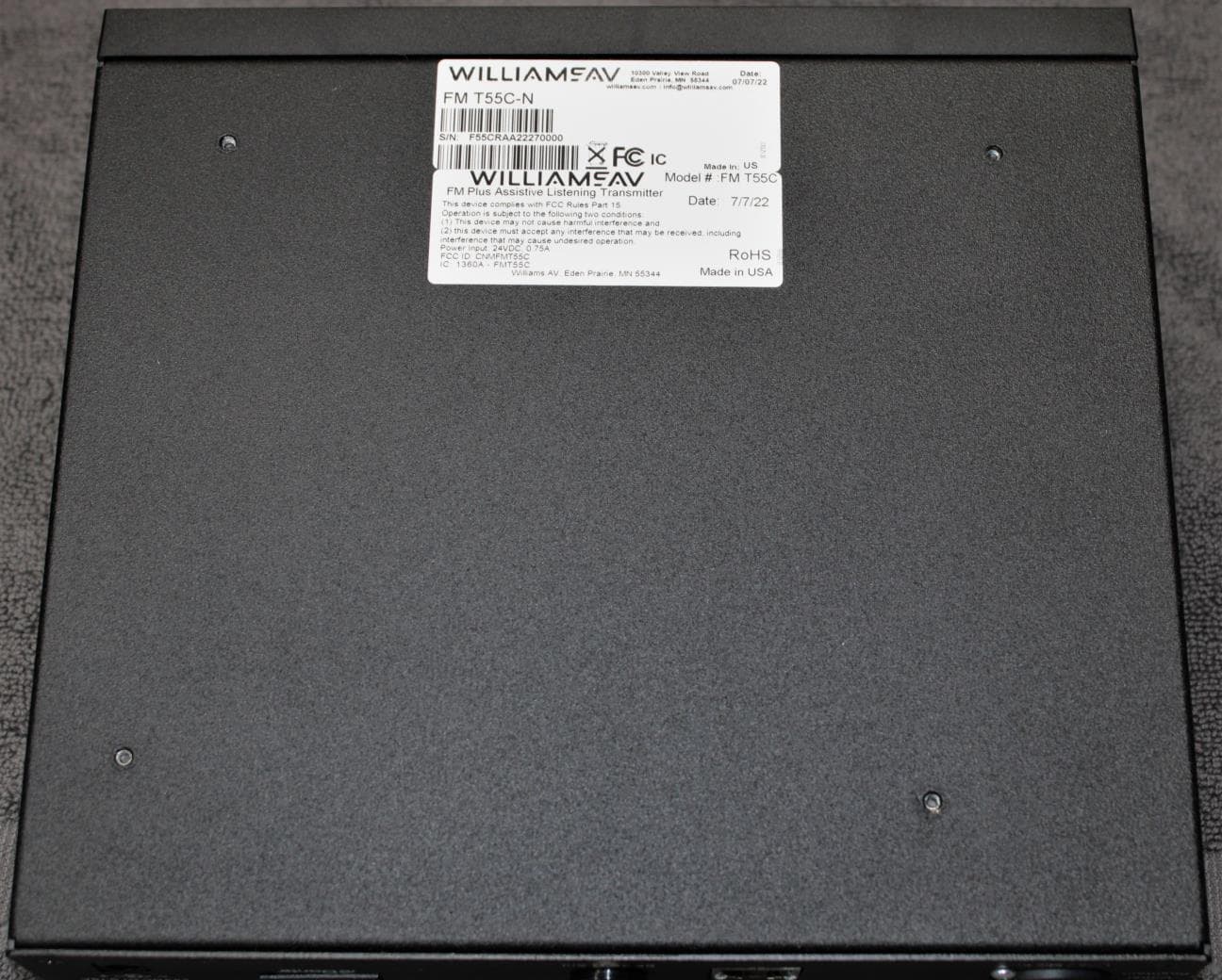
CNMFMT55C
Aug 28, 2022FM T55C
Equipment Class
GAT - Part 15 Auditory Assistance Device (Transmitter)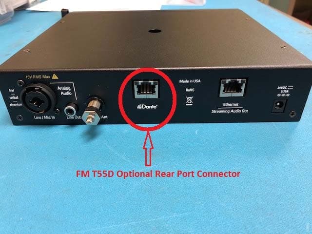
CNMFMT55
Mar 12, 2020FM T55, FM T55D
Equipment Class
GAT - Part 15 Auditory Assistance Device (Transmitter)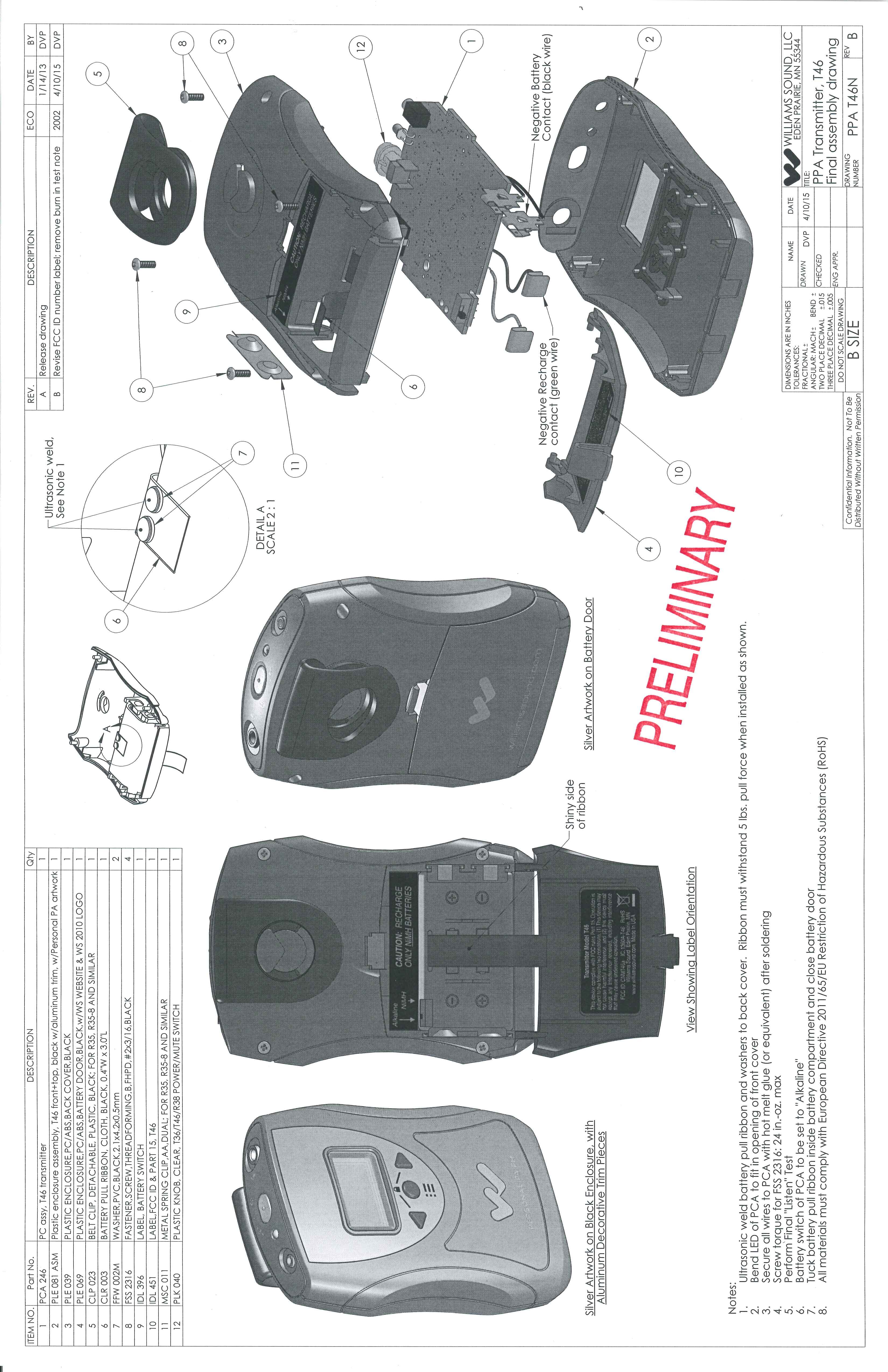
CNMT46A
May 03, 2015Battery operated auditory assistance transmitter
Equipment Class
DXT - Part 15 Low Power Transceiver, Rx Verified
CNMDLT300
Nov 20, 2014Portable Conference Transmitter
Equipment Class
DSS - Part 15 Spread Spectrum Transmitter
CNMT46
Oct 04, 2012Portable Hearing Assistance Transmitter
Equipment Class
GAT - Part 15 Auditory Assistance Device (Transmitter)