CNMT35Auditory Assistance Transmitter
Williams Sound, LLC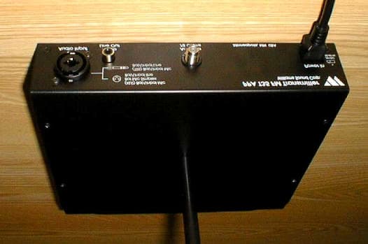
Click to zoom
Application Details
- Equipment Class
- GAT - Part 15 Auditory Assistance Device (Transmitter)
- Date of Grant
- Dec 02, 2002
- Application Purpose
- Original Equipment
- Date of Application
- Dec 02, 2002
- Equipment Note
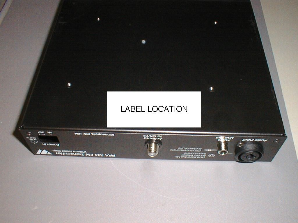
- Auditory Assistance Transmitter
- Frequency Range
- 72.02500000 - 75.97500000
- Company
- Williams Sound, LLC
- Country
- United States
Documents & Files
Document Text
Text extracted from the exhibit documents filed with the FCC. Open a document above to read the original.
Users Manual
Williams Sound ® Helping People Hear PERSONAL PA ® T35 Transmitter Wireless FM Listening System Transmitter Model PPA T35 Optional Receiver Models PPA R30, R7, R7-4, R19, R19-6 MANUAL ANDUSER GUIDE MAN 110 B Williams Sound ® Helping People Hear 3 MANUAL AND USERGUIDE ContentsPage SYSTEMOVERVIEW 4 QUICK SETUP INSTRUCTIONS5 D ETAILEDI NSTALLATIONINSTRUCTIONS6 S ELECT AL OCATION6 I NSTALLING THEA NTENNA6 WIRING AND CONNECTIONS 7 REARPANEL7 CONNECTING THEPOWERSUPPLY7 A UDIOSOURCECONNECTIONS7 CHOOSING ANAUDIOSOURCE FOR THEHEARINGIMPAIRED8 A VOIDING GROUNDL OOPS9 C ONNECTING TO A R ECORDINGDEVICE9 CONTROLS ANDFEATURES10 FRONTPANELCONTROLS10 LCD SCREENMENUS12 A PPLICATIONPRESETS13 BANDWIDTH14 FREQUENCY14 A UDIOSOURCE15 HIGHPASSFILTER15 LOWPASSFILTER16 C OMPRESSOR SLOPE16 C OMPRESSORGAIN17 RF OUTPUT18 RECEIVERINSTRUCTIONS19 WIDEBANDOPTIONS19 F REQUENCYCHANGEINSTRUCTIONS21 NARROWBANDOPTIONS22 RECEIVERMANAGEMENT24 BATTERYINFORMATION24 TROUBLE-SHOOTINGGUIDE25 WARRANTY27 S YSTEMSPECIFICATIONS28 4 SYSTEM OVERVIEW The PPA T35 is an FM Wide-band / Narrow-Band transmitter which operates in the 72-76 MHz frequency bandwidth. It is designed to be used with battery powered FM receivers: Compatible Williams Sound receivers include the R30, R7, R7-4 (Wide-Band), and the R19 and R19-6 (Narrow-band). Please contact Williams Sound Corp. for more information on available receivers: 800-843-3544. Or, visit us on the web: www.williamssound.com. Developed for hearing assistance in places of public access, the PPA T35 is designed for those who need help overcoming background noise, reverberation, or distance from the sound source. It includes a complete audio processor optimized for the needs of hearing impaired persons and is easily integrated with your existing sound system. The PPA T35 can also be used with a microphone as a stand-alone system. Your PPA T35 transmitter operates much like an FM radio station. The transmitter picks up the live audio directly from a microphone or sound system. Those sounds are then broadcasted over an FM radio signal. FM receivers are worn by the listener. The broadcast can be picked up from up to 500 feet away*. This allows the listener to sit anywhere in the audience and lis- ten to the broadcast as loud as needed without disturbing anyone else. Please read through this manual carefully. It includes important setup procedures and guide- lines for proper operation. If at any time you are having problems with this product, please contact Williams Sound toll free for assistance: 800-843-3544. NOTE: FCC regulations, section 15.21, requires the user to comply with the rules of transmitter operation. Any changes or modifications made by the user not expressly approved for compli- ance may result in the loss of all privelages and authority to operate the equipment. Power Phones Set Source Vo l u m e Audio Level Input Overload On Air + – +9 +6 +3 0 -3 -6 -9 -12 -15 -18 ^ ^ + - - + PPA T35 Sound System Amplifier PPA T35 Transmitter FM Receivers Microphone Line-Level Output Loudspeaker Digital Frequency Synthesized W illia m s S o u n d W illia m s S o u n d FIGURE1: OVERALLSYSTEMDIAGRAM *Range may be affected by metal structures. 500+ feet is the maximum operating range of the T35 Williams Sound ® Helping People Hear Williams Sound ® Helping People Hear 5 STEP 1: Position the PPA T35 transmitter near the sound system or mixer from which it will receive audio. STEP 2:Install the ANT 021 “rubber duckie” antenna. Gently thread the ANT 021 onto the stud recessed in the hole on the top of the transmitter. STEP 3:Connect the power supply to the “Power In” connector (Figure 5) located in the back of the T35. Press in the power button on the front of the T35. The “On Air” green LED indicator should illuminate. If not, go back and check the power connections. STEP 4:Select an application. The T35 has threepre-configured Appl- ication Presets to choose from: Hearing Assist, Musicand Voice. The performance of the T35 is optimized for each selected application. Using the menu control buttons on the front of the T35 (Figure 2), press the “ “ button to access the “Application Presets” LCD screen. Press the “+” and “-” menu buttons to alternate between Hearing Assist, Music and Voice selection. When the desired Application Preset is displayed, press the “Set” button to save the change into memory. STEP 5:The T35 is shipped from the factory in wideband mode with the frequency set to 72.900 MHz. To change the frequency or bandwidth on the T35, refer to the instructions on page 14. STEP 6:Configure the T35 for the appropriate audio source. Using the menu control buttons on the front of the T35 (Figure 2), press the “ “ button to access the “Audio Source” LCD screen. Using the “+” and “-” menu buttons (Figure 2), choose between MIC, SIM- PLEX-MIC, or LINE. When the desired audio input is displayed, press the “Set” button to save the change into memory. Lastly, con- nect the audio source to the audio input jack in the rear of the T35 transmitter. STEP 7:With the audio source playing, adjust the Audio Level control on the T35 so that the green “0 dB” LED generally lights and the red “+9 dB” LED lights occasionally: Press the Audio Level “+” button to increasethe audio level in .5dB steps. Press the Audio Level “-” button to decrease the audio level in .5dB steps. See Figure 3. STEP 8:Listen with an FM receiver (see pages 19-23 for compatible Williams Sound receivers). Install the batteries, plug in the earphone, turn on the receiver and walk around the listening area. The sig- nal should be clear and quite loud when the volume is turned up. IMPORTANT: The FM receiver being used with the T35 transmitter will need to be on the same frequency and bandwidth as the transmitter. To retune the receiver, see page 21. Please r ead through this manual carefully for detailed instructions and setup procedures. ^ ^ FIG. 2: LCD Menu Controls Front panel of the T35 Set ^ ^ - + FIG. 3: Audio Input Controls Front panel of the …
Text truncated - open the document above for the full version.
Block Diagram
Figure 1. T35 System Block Diagram. Figure 2. RF Subsystem Block Diagram Microprocessor Audio Processor RF Transmitter Audio Source Antenna VCO & MODU- LATOR PLL Reference Oscillator VGA RF Amp Directional Coupler Level Detector Error Amp RF Power Control Audio Input to RF Microprocessor Controls Figure 3. Digital Control Subsystem Block Diagram Microprocessor 4 MHz Oscillator Audio Sample VCO Sample Switch MUX Contr ol Latch CLK DATA LATC H LCD Display LED Driver CLK LED Driver DATA LED Driver Latch Latc h MUX Figure 4. Audio Sub-system Block Diagram. Overload Detector Amp Buffe High Pass Filter Low Pass Filter Pre- emphasis Compress or / Wide Band Clipper Narrow Band Mete r Buffe Modulati on Phones Amp Simple x
Operational Description
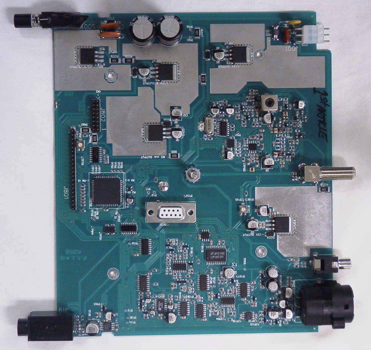
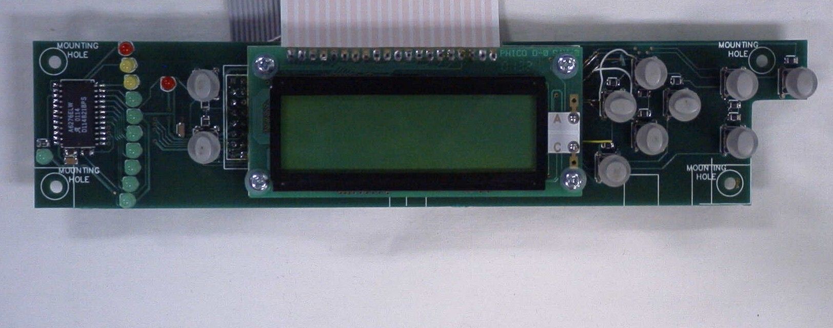
Page 1 11/19/02 T35 Theory of Operation Page 1 11/19/02 T35 Theory of Operation T35 Theory of Operation Preliminary Revision PA Introduction: This document describes the theory of operation for the T35 transmitter. It provides basic operating concepts and criteria for successful understanding of the properties of the transmitter. Overview: The T35 is a RF transmitter designed to support Voice, Music, and Hearing Assistance transmissions over short distances (up to 500 feet). The T35 provides both wide and narrow band FM signals at frequencies from 72.025 to 75.975 MHz. A variety of selectable audio processes are included, and typical audio connectors are supported. This product is intended for sale in the United States and is subject to US rules and specifications (Part 15.237). There are 17 possible wide band frequencies and 77 narrow band frequencies as shown below. RF Channels: The T35 will transmit on any one of the channels specified in the tables below. Wide Band Channels (MHz) Narrow Band Channels (MHz) 72.1 72.2 72.025 72.275 72.525 72.775 74.650 75.325 75.575 75.825 72.3 72.4 72.050 72.300 72.550 72.800 74.675 75.350 75.600 75.850 72.5 72.6 72.075 72.325 72.575 72.825 74.700 75.375 75.625 75.875 72.7 72.8 72.100 72.350 72.600 72.850 74.725 75.400 75.650 75.900 72.9 75.4 72.125 72.375 72.625 72.875 74.750 75.425 75.675 75.925 74.7 75.6 72.150 72.400 72.650 72.900 74.775 75.450 75.700 75.950 75.3 75.8 72.175 72.425 72.675 72.925 75.225 75.475 75.725 75.975 75.5 72.200 72.450 72.700 72.950 75.250 75.500 75.750 75.7 72.225 72.475 72.725 72.975 75.275 75.525 75.775 75.9 72.250 72.500 72.750 74.625 75.300 75.550 75.800 Table 1. List of all wide band and narrow band frequencies possible with the T35. Physical Configuration: The T35 is enclosed in a half rack case, and may be operated in either a fixed mode or a portable mode. In either case, the unit operates from standard 110 VAC, 60 Hz electrical power. The unit may be rack mounted with an available kit. Four antennas are available, depending on the application. The ANT 005 is a coaxial half wave dipole. The ANT 24 is a short dipole. The ANT 021 is a short rubber duck antenna which mounts through a hole in the top of the case, and the ANT 025 is a collapsible whip which also mounts through a hole in the top of the case. The antenna type may be selected depending on the application. Page 2 11/19/02 T35 Theory of Operation Page 2 11/19/02 T35 Theory of Operation Figure 1. T35 System Block Diagram. T35 System Level Description: See Figure 1 above. Audio Processor: The audio processor takes an input audio signal and processes it to provide for a variety of applications, with microprocessor control to inhibit conflicting selections. It accepts an audio signal from a variety of sources. For Convenience the source is shown above as a microphone, but it might be one of several types of microphones, or any line level source as well. The audio processor, under the control of the microprocessor, will adapt to any of these sources (NOT a 70 volt input signal!). Both low pass and high pass audio filters are selectable for a number of configurations. A variety of compressor slopes and gains are also available. RF Transmitter: The RF transmitter circuits, under microprocessor control, will generate any of the RF frequencies listed in Table 1. It accepts the processed audio from the Audio processor, and generates a high quality FM signal. This signal is amplified and controlled by transmitter circuitry, and routed to one of several antennas. Microprocessor: The microprocessor is the controller for all functions of the T35. It interprets front panel switch presses, executes the selected commands, and displays relevant information on the front panel LCD, LED bar graph, and “on air” LED. Front Panel Display: The front panel has all the controls for operating the T35, and displays all operating information. Chassis: The chassis provides all mechanical support and shielding for the T35 transmitter. Microprocessor Audio Processor RF Transmitter Audio Source Antenna Page 3 11/19/02 T35 Theory of Operation Page 3 11/19/02 T35 Theory of Operation RF Circuit Description: See Figure 2 below. The RF circuits of the T35 generate a controlled Frequency Modulated RF output controlled by the transmitter’s microprocessor. The modulating signal is supplied by the audio processor circuit. The microprocessor controls both the frequency and amplitude of the RF output signal. The RF circuits operate from a single +15 Volt supply. Figure 2. RF Subsystem Block Diagram Circuit Description: The following paragraphs describe the RF circuits of the T35. Please reference SCH 180. Also, see the block diagram in Figure 2 above. Reference Oscillator: The reference oscillator is a low cost 4 MHz oscillator which provides clock signals to both the PLL chip and the Microprocessor. Separate buffer circuits keep the microprocessor’s noise and signals from influencing the RF, contributing to the overall low noise of the transmitter. The oscillator is locked to the 4 MHz crystal, and is trimmed by adjusting C507. VCO/FM Modulator: The VCO (Voltage Controlled Oscillator) is a low noise, low distortion tuned oscillator that generates the transmitter’s RF signal in the 72 to 76 MHz bands. Because the signal output is a nearly perfect sine wave, less filtering is required later. Power supply noise is decoupled by R603 and C602. The oscillator is a modified Colpitts circuit, having two varactors, one for tuning (D601) and the other for modulation (D602). T601 provides the necessary oscillator trim function, plus the secondary winding conveys the RF output to the VCA (Voltage Controlled Amplifier), matching impedance and helping eliminate possible ground loops. VCO & MODU- LATOR PLL Reference Oscillator VGA RF Amp Directional Coupler Level Detector Error Amp RF Power Control Audio Input to RF Modulator Microprocessor Controls Page 4 11/19/02 T35 Theory of Operation Page 4 11/19/02 T35 Theory o…
Text truncated - open the document above for the full version.
Test Report
TIMCOTIMCO ENGINEERING INC. 849 NW State Road 45 Newberry, Florida 32669 http://www.timcoengr.com 888.472.2424 F 352.472.2030 email: [email protected] APPLICANT: WILLIAMS SOUND CORPORATION FCC ID: CNMT35 REPORT #: W\WSC\1085TU2\1085TU2TestReport.doc COVER SHEET Test Report Product Name: MODEL T-35 AUDITORY ASSISTANCE TRANSMITTER FCC ID: CNMT35 Applicant: WILLIAMS SOUND CORPORATION 10399 W. 70th Street Eden Prairie, MN 55344 Date Receipt: OCTOBER 24, 2002 Date Tested: NOVEMBER 8, 2002 TIMCOTIMCO ENGINEERING INC. 849 NW State Road 45 Newberry, Florida 32669 http://www.timcoengr.com 888.472.2424 F 352.472.2030 email: [email protected] APPLICANT: WILLIAMS SOUND CORPORATION FCC ID: CNMT35 REPORT #: W\WSC\1085TU2\1085TU2TestReport.doc TABLE OF CONTENTS TABLE OF CONTENTS APPLICANT: WILLIAMS SOUND CORPORATION FCC ID: CNMT35 REPORT CONTAINING: PAGE 1-4...........TEST EQUIPMENT LIST PAGE 5.............TEST PROCEDURE PAGE 6.............MODULATION CHARACTERISTICS AND EMISSION TYPES PAGE 7.............AUDIO FREQUENCY RESPONSE PLOT – NARROW BAND PAGE 8.............MODULATION LIMITING PLOT 300 Hz – NARROW BAND PAGE 9.............MODULATION LIMITING PLOT 2500 Hz – NARROW BAND PAGE 10............MODULATION LIMITING PLOT 15000 Hz – NARROW BAND PAGE 11............AUDIO FREQUENCY RESPONSE PLOT – WIDE BAND PAGE 12............MODULATION LIMITING PLOT 300 Hz – WIDE BAND PAGE 13............MODULATION LIMITING PLOT 2500 Hz – WIDE BAND PAGE 14............MODULATION LIMITING PLOT 15000 Hz – WIDE BAND PAGE 15-21.........RADIATION INTERFERENCE TEST DATA PAGE 22-24.........POWER LINE CONDUCTED INTERFERENCE PAGE 25............OCCUPIED BANDWIDTH PAGE 26............OCCUPIED BANDWIDTH PLOT – NARROW BAND PAGE 27............OCCUPIED BANDWIDTH PLOT – WIDE BAND PAGE 28............OCCUPIED BANDWIDTH PLOT - CW EXHIBITS CONTAINING: PAGE 1.............FCC ID LABEL SAMPLE PAGE 2.............SKETCH OF FCC ID LABEL LOCATION PAGE 3.............BLOCK DIAGRAMS PAGE 4.............SCHEMATICS PAGE 5.............THEORY OF OPERATION PAGE 6.............INSTRUCTION MANUAL PAGE 7.............EXTERNAL PHOTOS PAGE 8.............INTERNAL PHOTOS TIMCOTIMCO ENGINEERING INC. 849 NW State Road 45 Newberry, Florida 32669 http://www.timcoengr.com 888.472.2424 F 352.472.2030 email: [email protected] APPLICANT: WILLIAMS SOUND CORPORATION FCC ID: CNMT35 REPORT #: W\WSC\1085TU2\1085TU2TestReport.doc Page 1 of 28 EMC Equipment List DEVICE MFGR MODEL SERNO CAL/CHAR DATE DUE DATE or STATUS X 3-Meter OATS TEI N/A N/A Listed 12/22/99 12/22/02 3/10-Meter OATS TEI N/A N/A Listed 3/26/01 3/26/04 Receiver, Beige Tower Spectrum Analyzer (Tan) HP 8566B Opt 462 3138A07786 3144A20661 CAL 8/31/01 8/31/03 RF Preselector (Tan) HP 85685A 3221A01400 CAL 8/31/01 8/31/03 Quasi-Peak Adapter (Tan) HP 85650A 3303A01690 CAL 8/31/01 8/31/03 X Receiver, Blue Tower X Spectrum Analyzer (Blue) HP 8568B 2928A04729 2848A18049 CHAR 10/22/01 10/22/03 X RF Preselector (Blue) HP 85685A 2926A00983 CHAR 10/22/01 10/22/03 X Quasi-Peak Adapter (Blue) HP 85650A 2811A01279 CHAR 10/22/01 10/22/03 X Biconnical Antenna Electro-Metrics BIA-25 1171 CAL 4/26/01 4/26/03 Biconnical Antenna Eaton 94455-1 1096 CAL 10/1/01 10/1/03 Biconnical Antenna Eaton 94455-1 1057 CHAR 3/15/00 3/15/02 BiconiLog Antenna EMCO 3143 9409-1043 X Log-Periodic Antenna Electro-Metrics LPA-25 1122 CAL 10/2/01 10/2/03 Log-Periodic Antenna Electro-Metrics EM-6950 632 CHAR 10/15/01 10/15/03 Log-Periodic Antenna Electro-Metrics LPA-30 409 CHAR 10/16/01 10/16/03 Dipole Antenna Kit Electro-Metrics TDA-30/1-4 152 CAL 3/21/01 3/21/04 TIMCOTIMCO ENGINEERING INC. 849 NW State Road 45 Newberry, Florida 32669 http://www.timcoengr.com 888.472.2424 F 352.472.2030 email: [email protected] APPLICANT: WILLIAMS SOUND CORPORATION FCC ID: CNMT35 REPORT #: W\WSC\1085TU2\1085TU2TestReport.doc Page 2 of 28 DEVICE MFGR MODEL SERNO CAL/CHAR DATE DUE DATE or STATUS Dipole Antenna Kit Electro-Metrics TDA-30/1-4 153 CHAR 11/24/00 11/24/03 Double-Ridged Horn Antenna Electro-Metrics RGA-180 2319 CAL 12/19/01 12/19/03 Horn Antenna Electro-Metrics EM-6961 6246 CAL 3/21/01 3/21/03 Horn Antenna ATM 19-443-6R None No Cal Required Passive Loop Antenna EMC Test Systems EMCO 6512 9706-1211 CHAR 7/10/01 7/10/03 Line Impedance Stabilization . . . Electro-Metrics ANS-25/2 2604 CAL 10/9/01 10/9/03 Line Impedance Stabilization . . . Electro-Metrics EM-7820 2682 CAL 3/16/01 3/16/03 Termaline Wattmeter Bird Electronic Corporation 611 16405 CAL 5/25/99 5/25/01 Termaline Wattmeter Bird Electronic Corporation 6104 1926 CAL 12/12/01 12/12/03 Oscilloscope Tektronix 2230 300572 CHAR 2/1/01 2/1/03 Temperature Chamber Tenney Engineering TTRC 11717-7 CHAR 1/22/02 1/22/04 AC Voltmeter HP 400FL 2213A14499 CAL 10/9/01 10/9/03 AC Voltmeter HP 400FL 2213A14261 CHAR 10/15/01 10/15/03 AC Voltmeter HP 400FL 2213A14728 CHAR 10/15/01 10/15/03 X Digital Multimeter Fluke 77 35053830 CHAR 1/8/02 1/8/04 Digital Multimeter Fluke 77 43850817 CHAR 1/8/02 1/8/04 Digital Multimeter HP E2377A 2927J05849 CHAR 1/8/02 1/8/04 Multimeter Fluke FLUKE-77-3 79510405 CAL 9/26/01 9/26/03 TIMCOTIMCO ENGINEERING INC. 849 NW State Road 45 Newberry, Florida 32669 http://www.timcoengr.com 888.472.2424 F 352.472.2030 email: [email protected] APPLICANT: WILLIAMS SOUND CORPORATION FCC ID: CNMT35 REPORT #: W\WSC\1085TU2\1085TU2TestReport.doc Page 3 of 28 DEVICE MFGR MODEL SERNO CAL/CHAR DATE DUE DATE or STATUS Peak Power Meter HP 8900C 2131A00545 CHAR 1/26/01 1/26/03 Digital Thermometer Fluke 2166A 42032 CAL 1/16/02 1/16/04 Thermometer Traulsen SK-128 CHAR 1/22/02 1/22/04 X Temp/Humidity gauge EXTech 44577F E000901 CHAR 1/22/02 1/22/04 Frequency Counter HP 5352B 2632A00165 CAL 11/28/01 11/28/03 Power Sensor Agilent Technologies 84811A 2551A02705 CAL 1/26/01 1/26/03 Service Monitor IFR FM/AM 500A 5182 CAL 11/22/00 11/22/02 Comm. Serv. Monitor IFR FM/AM 1200S 6593 CAL 5/12/02 5/12/04 Signal Generator HP 8640B 2308A21464 CAL 11/15/01 11/15/03 Modulation Analyzer HP 8901A 3435A06868 CAL 9/5/01 9/5/03 Near Field Probe HP HP…
Text truncated - open the document above for the full version.
Contact Information
Applicant
Per W. Danzl(VP of Engineering)
Test Firm
Timco Engineering, Inc.S Sanders
Technical Specifications
| # | Rule Parts | Frequency Range | Power Output |
|---|---|---|---|
| 1 | 15.237 | 72.025 MHz - 75.975 MHz | - |
Other Applications from Williams Sound, LLC
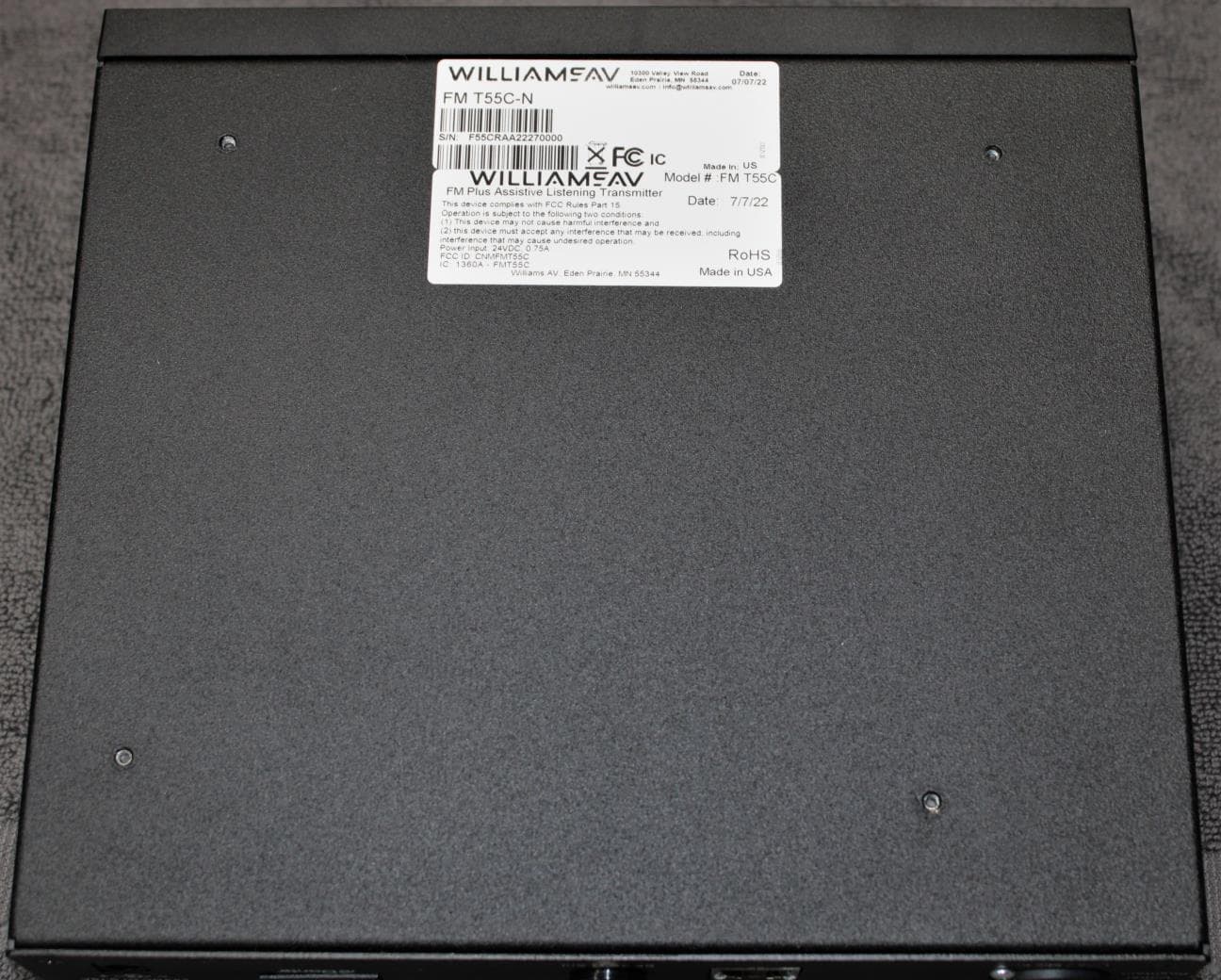
CNMFMT55C
Aug 28, 2022FM T55C
Equipment Class
GAT - Part 15 Auditory Assistance Device (Transmitter)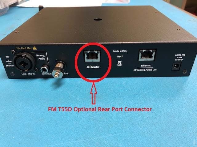
CNMFMT55
Mar 12, 2020FM T55, FM T55D
Equipment Class
GAT - Part 15 Auditory Assistance Device (Transmitter)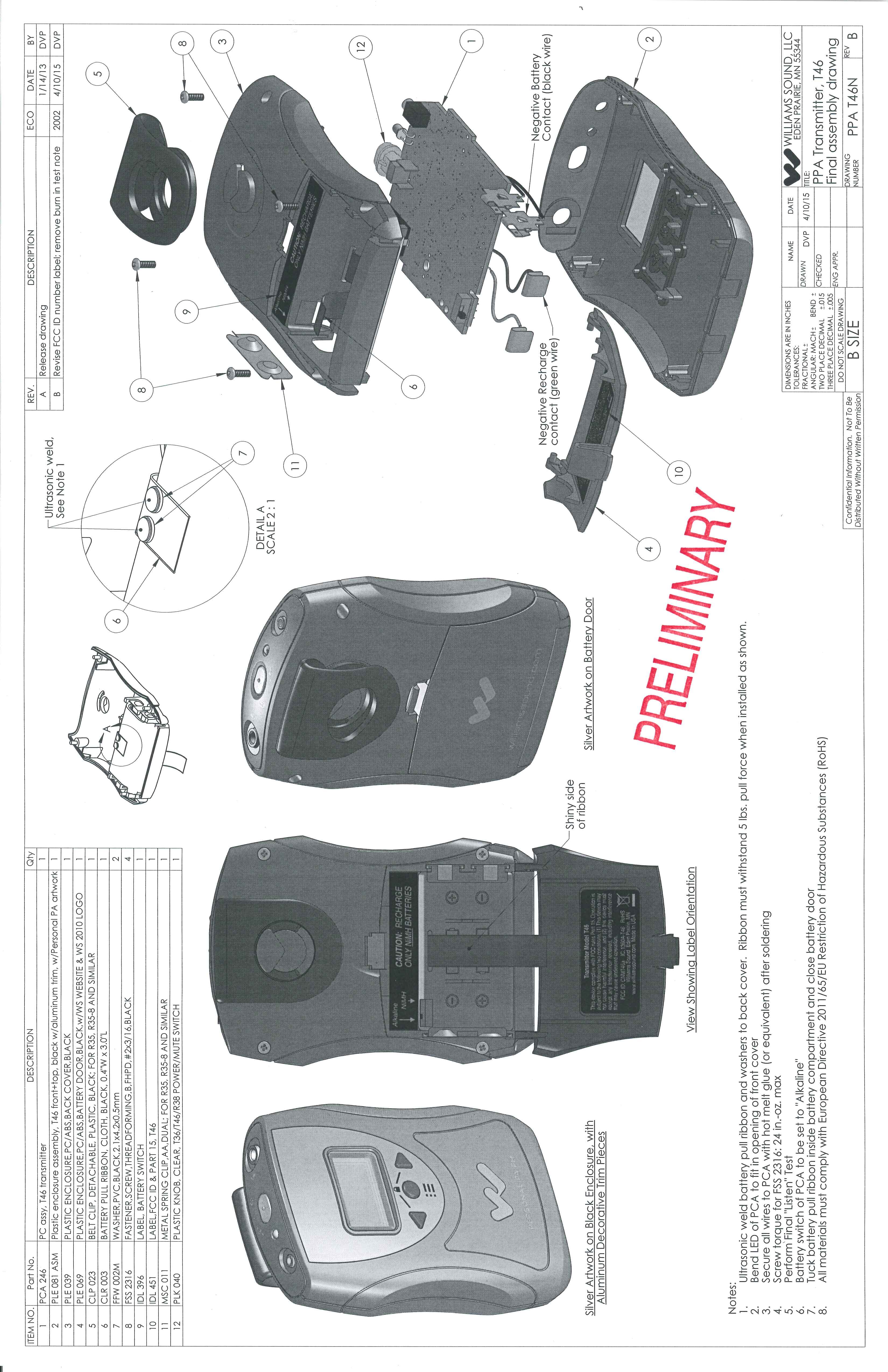
CNMT46A
May 03, 2015Battery operated auditory assistance transmitter
Equipment Class
DXT - Part 15 Low Power Transceiver, Rx Verified
CNMDLT300
Nov 20, 2014Portable Conference Transmitter
Equipment Class
DSS - Part 15 Spread Spectrum Transmitter
CNMT46
Oct 04, 2012Portable Hearing Assistance Transmitter
Equipment Class
GAT - Part 15 Auditory Assistance Device (Transmitter)