CWW7VB916-0140800VC015-0R2RF
Crescend Technologies LLC
Click to zoom
Application Details
- Equipment Class
- AMP - Amplifier
- Date of Grant
- Feb 15, 2000
- Application Purpose
- Original Equipment
- Date of Application
- May 16, 1999
- Equipment Note
- 800VC015-0R2RF
- Frequency Range
- 820.00000000 - 960.00000000
- Company
- Crescend Technologies LLC
- Country
- United States
Documents & Files
Document Text
Text extracted from the exhibit documents filed with the FCC. Open a document above to read the original.
Users Manual
VOCOM Products RF Amplifiers Instruction Manual For Model 800VC28-015-XXR RF Power Amplifiers THE FOLLOWING INSTRUCTIONS ARE FOR USE BY QUALIFIED RF SERVICE PERSONNEL ONLY. SERVICE PERFORMED ON VOCOM’S AMPLIFIERS MAY VOID THE MANUFACTURER’S WARRANTY VOCOM Products Company, L.L.C. 2255 Lois Drive Suite 1 Rolling Meadows, IL 60008 Quality since 1979 TABLE OF CONTENTS 800VC28-015-XXR RF POWER AMPLIFIER SECTION 1.0OPERATING INSTRUCTIONS SECTION 2.0SPECIFICATIONS SECTION 3.0TEST SECTION 4.0PROPER AMPLIFIER SETUP SECTION 5.0APPLICATION NOTE SECTION 1: OPERATING INSTRUCTIONS GENERAL: To effectively use the 800VC28-015-XXR RF power amplifier, the operation capabilities of the unit must be known. This section describes input/output connections and environmental operating conditions. Understand the operating of limitations of the amplifier before installation is attempted. OPERATING VOLTAGES: Warning: This unit is designed for operation from 28 volts DC negative ground systems. The chassis must be kept at earth potential. The negative (black) DC power lead is connected directly to the chassis. Operation in positive ground systems may cause injury. All power measurements and specifications are met at 28 volts DC as measured at the DC input terminals. For best performance, a regulated power supply is recommended. Operating voltage range is from 24-28 volts. Power will be reduced slightly at DC voltages below 28 volts. Operation a 28 volts or higher is to be avoided as this will significantly reduce transistor life. POWER CORD IDENTIFICATION: Two cables extend from the amplifier. The RED lead is to be connected to the POSITIVE power supply terminal. The BLACK lead is to be connected to the NEGATIVE power supply terminal and earth ground. Use caution not to reverse the DC polarity and do not connect to an AC power line. OPERATING TEMPERATURE: The amplifier may be operated when the ambient air is between O and 50 degrees centigrade. If operated in a closed cabinet, verify that the air temperature flowing over the heat sink is in this range. The amplifier/power supply combination may generate over 1500 watts of heat. The amplifier is cooled by convection flow across the heat sink fins of the unit. Maintain a minimum of 4 inches clearance. A thermal shut-off circuit is provided that will interrupt the DC power input to the first RF stage should the heat sink rise above 60 degrees C. Operation in confined areas may cause the unit to shut-off thermally. Installations where thermal cut-off occurs frequently should be avoided. The unit may be stored in temperatures between -20 and + 70 degrees centigrade. Keep the fan intakes free of dust. TROUBLE SHOOTING: LOW POWER OUTPUT: The most common amplifier problem is low power output. If the installation test shown in Section 3 is run the power input/output specification on the nameplate should be met, especially when working into a dummy load, since this is essentially the test run at the factory. If working with BIRD wattmeters, remember that the power output reading is specified at +/-5% of full scale. In other words, a wattmeter with a 100w element gives readings of +/-5 watts when the wattmeter is reading full scale. Mid-scale readings have much lower accuracy. Always use an element closest to full scale for maximum accuracy. Treat your element with extreme care. Dirty or dropped elements always read low. Make sure that your power supply is adjusted to 28 volts. The input/output powers specified on the nameplate were taken at 28 volts. Measure the voltage at the amplifier terminals to be sure all the DC connections are tight and that the amplifier is seeing 28 volts during operation. Check the manufacturer's ratings to be sure the CONTINUOUS rating of the power supply is sufficient to power the amplifier. If the power supply is slumping, the amplifier output will go down with the voltage. Look at the drive power while the amplifier is operating. Many exciters will put out different powers into even slightly different loads. Low drive power will produce low output power. Do not assume that your exciter output power with the exciter running into a dummy load will be the same as when the exciter is running the amplifier. A strong RF field can sometimes cause an exciters to increase or decrease power as well as go spurious. In-band spurious signals maybe amplified. The change in signal level will show up on the input wattmeter. RF fields can also cause linear power supplies to fall out of regulation. This should be seen on a voltmeter (CAUTION: RF can effect digital voltmeters, too.) Low (or high) output powers can be the result of a high output SWR. Carefully check your loads and connecting cables. NO OUTPUT POWER: After checking the above items, be aware that there is protection circuitry. Check with the factory if you suspect that the internal protection has or is operating. As a rule, if the front panel light and fan are operating and output is zero, the SWR circuit has operated (usually with an audible click upon key-up.) If the SWR protection were operating, you would notice the output wattmeter "jump" briefly upon key up and then return to zero. If the front panel light does not light, either the input drive isn't high enough to trigger the amplifier on or the amplifier has disconnected itself from DC power. The amplifier will reset itself when it cools down. (Some power supplies will "spring up" in voltage when a heavy load is released and settle down to normal after 100-200 milliseconds. This can damage an amplifier.) If all else fails, give us a call. We'll be glad to help! SECTION 2: SPECIFICATIONS WARNING:Do not exceed 15 watts output. Do not exceed nameplate drive power by more than 5%. Do not exceed 28.0 volts while operating. FREQUENCY: 840-960 MHz range. Factory set to specific frequency on ID label. FREQUENCY RANGE: May be operated within + or - 10 MHz of the factory set frequency without tuning. INPUT DRIVE POWER: As specified on amplifier ID na…
Text truncated - open the document above for the full version.
Operational Description
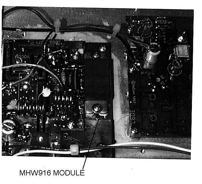
VOCOM Products CompanyCWW7VB9 16-01402 Operational Description CWW7VB916-0140 Identification of equipment: A nameplate on front panel identifies the equipment (RF Amplifier) as: Model Number: 800V28-015-OR2R And by a separate label reading: FCC ID: CWW7VB916-0140 Operational description: The equipment to designed to operate as an amplifier in the frequency range of 840-950 MHz. providing power gain for FM and PM exciters. Type of emission,36F3 Frequency range840-950 MHz. Power level15 watts Maximum power rating15 watts DC Voltages and currents:22-28 VDC at 2-3 amperes Function of active devices: The sole RF active component is a hybrid amplifier module manufactured by Motorola P/N: MHW916. The MHW916 is a class AB module; however, VoCom will use the device for analog FM, not multi-channel or for linear applications. This module supplies nearly (20 dB gain over the specified bandwidth. Module is identified as U1 on the RE deck schematic. Other active components are voltage regulators used for power control (Q1-Q3) and RF sensing stages used to operate cooling fans during operation. Description of circuits employed for suppression of spurious outputs: Refer to RF deck schematic. Bypassing of the DC leads to the module is present to reduce low frequency coupling from output to input stages. Harmonics are attenuated internal to the module at levels of -60 dBc. An additional 3 pole filter is added to the output stage to assure compliance to -70 dBc or greater.
Parts List/Tune Up Info
PARTS LIST/TUNE UP INFORMATION Parts List: The only active RF transistor in the amplifier is Motorola's MHW916. Tune Up Information There are no adjustments needed to tune this amplifier. Alignment test procedure is to simply test for -65 dBc conducted harmonic compliance and stability.
Schematics
To Power control 800V28015-0R2RSheet 1 To RF OutputConnector To PowerControl U1 To Power control C-) \0Ca0 To RE cutout connector
Schematics
-~ Q1 DETECTS INPUT RF AND DRIVES 02 AND 03 TO OPERATE FANSQ4 DETECTS REVERSE POWER AT OUTPUT AND OPERATES K1 IF RF IS PRESENT AT INPUT (Q2 ON) K1 LATCHES THROUGH ITS OWN CONTACT AND R10. K1 RELEASES WHEN INPUT DRIVE POWER IS REMOVED (Q2 OFF) R8 ADJUSTS SWR THRESHOLD.R1 IS FACTORY SELECTED AND MAY VARY WITH DRIVE POWER SET- UP UP TO 3 FANS AND1 DR MORE LEDS OUTPUT CONNECTOR J3 TO ONE OUTPUTJO SWITCHED +12 OUT ( REMOVES +12 ON FAULT DETECT 3 -~
Test Report
TEST REPORT TEST DATA: Radiated Spurious Emissions Received FrequencyReceived LevelRelative 860 MHz-1 dBm0 dB 1720 MHz-62 dBm-61 dB 2580 MHz-67 dBm-66 dB 3440 MHz-72 dBm-71 dB 4300 MHz-85 dBm-84 dB 5160 MHz-79 dBm-78 dB 6020 MHz-89 dBm-88 dB 6800 MHz and higherNot detectedNot detected Signals are referenced to absolute received power levels in dBm at 50 ohms. Relative levels are referenced to the received fundamental power level. Amplifier was operated into a dummy load for the radiated tests. Reference level was determined as follows 15 mW into 1/2 wave antenna at 860 M1Hz Received level was - 31 dBm. If 15 watts had been transmitted, the signal would have been 30 dB higher, or -1 dBm. Harmonics were received with 1/2 wave dipole cut to harmonic frequency. Antennas were moved vertically until a maximum reading was found. Conclusion. All radiated harmonics were less than -60 dB below the radiated carrier at 15 watts output. Requirement of External Power Amplifiers Per Parts 97 and 2.1005 Measured harmonic levels operated at 860 MHz: HarmonicMeasured Level 2 nd 1720 MHz-72 dBc 3 rd 2580 MHz-75 dBc 4 th 3440 MHzNot detected >80 dBc Next Page is the Test Set Up.
Contact Information
Applicant
James Hougo(President)
Technical Specifications
| # | Rule Parts | Frequency Range | Power Output | Emission |
|---|---|---|---|---|
| 4 | 22,9 | 820 MHz - 960 MHz | 15 W | F7D |
Other Applications from Crescend Technologies LLC
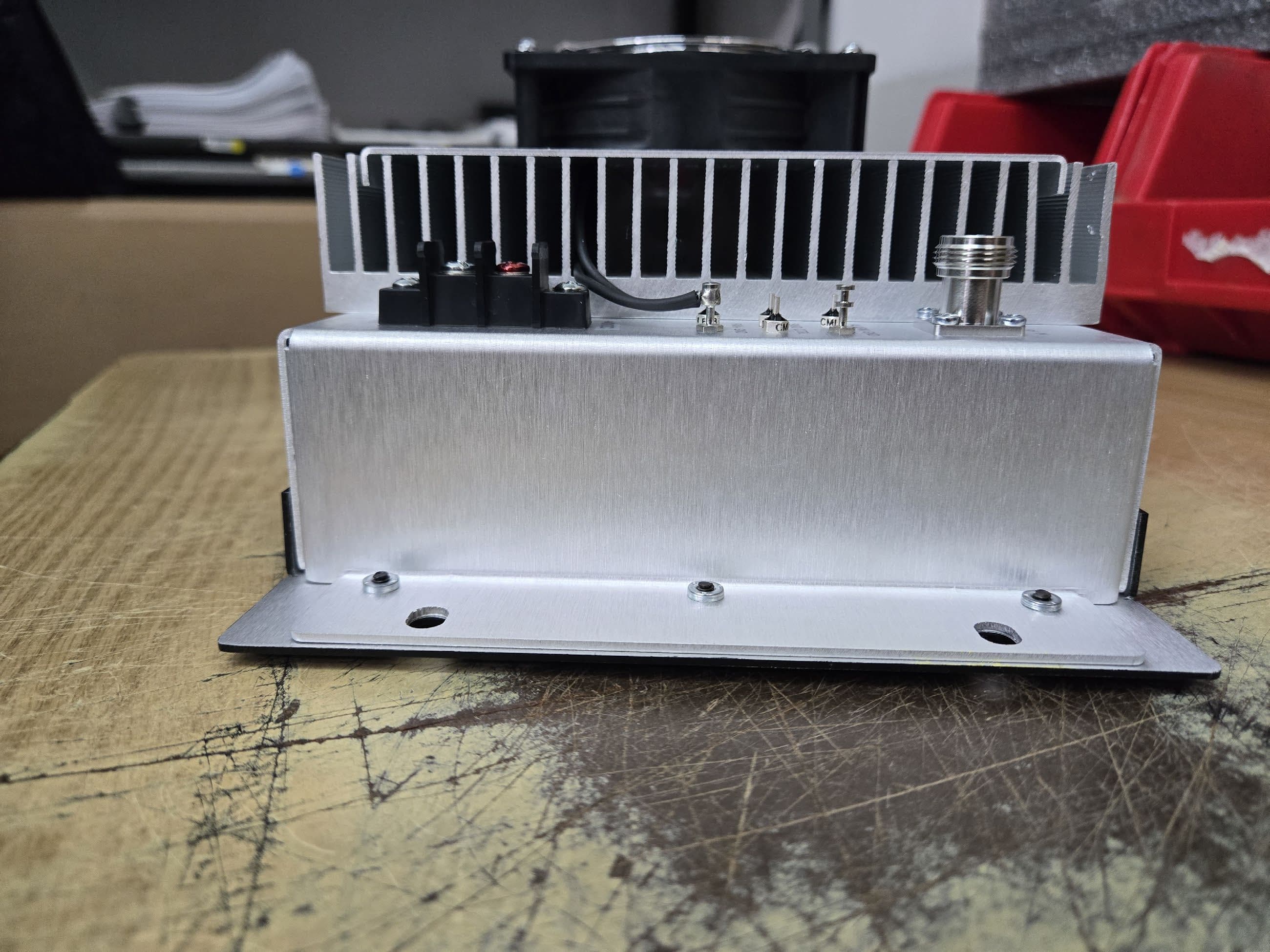
CWWP25XXDE4
Sep 17, 2025Power Amplifier AB to C Class
Equipment Class
B2I - Part 20 Industrial Booster (CMRS)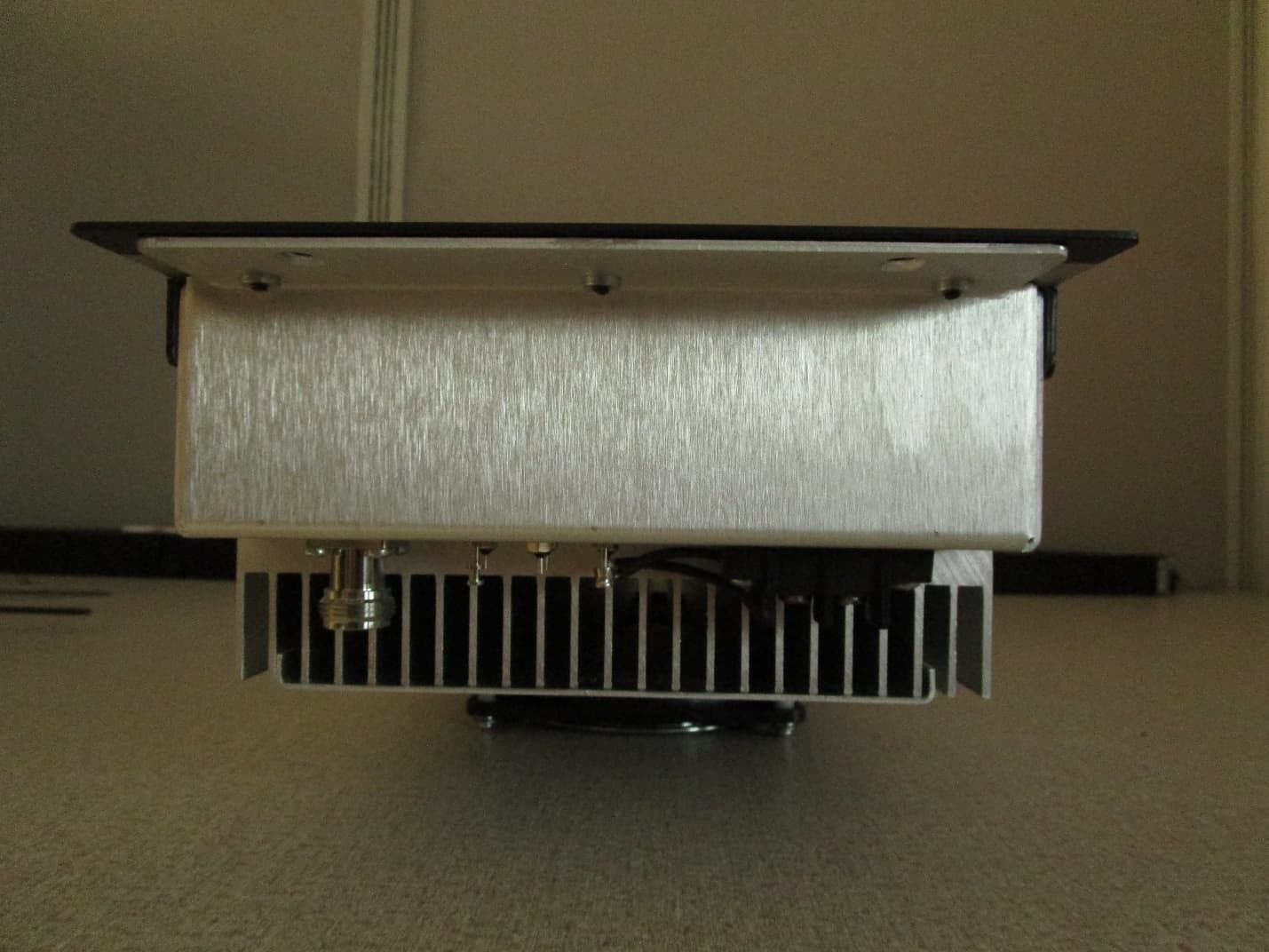
CWWP10XXDE1
Mar 10, 2020VHF AMPLIFIER
Equipment Class
B9B - Part 90 Class B Industrial Booster (non-SMR)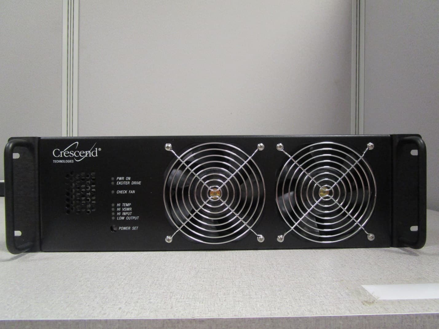
CWWP25XXHA3
Jan 27, 2020HIGH BAND HIGH POWER AMPLIFIER
Equipment Class
B9A - Part 90 Class A Industrial Booster (non-SMR)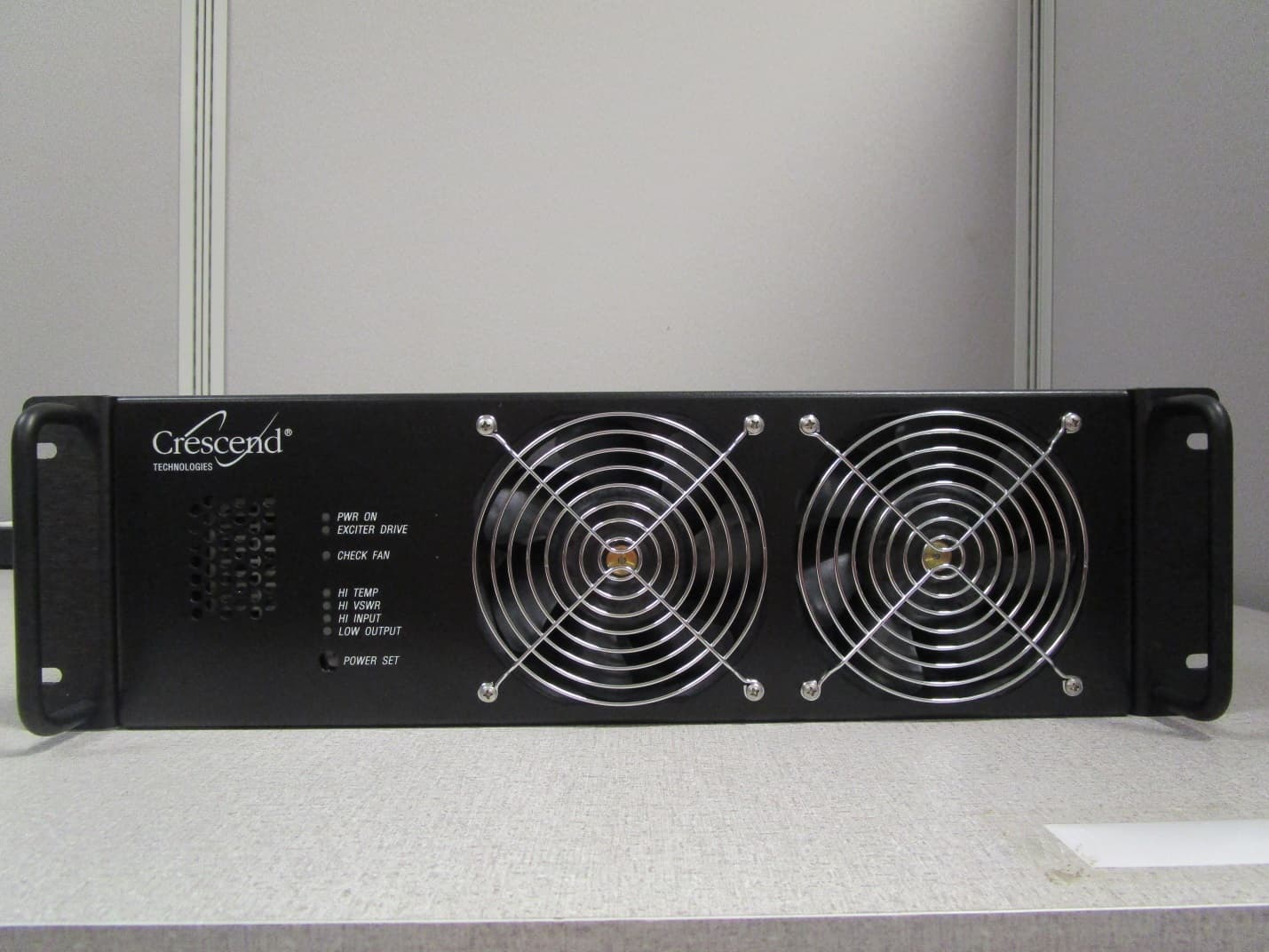
CWWP25XXGA3
Jan 21, 2020LOW BAND HIGH POWER AMPLIFIER
Equipment Class
B9A - Part 90 Class A Industrial Booster (non-SMR)
CWWP2RTK450
May 10, 201525Watt One-Way Amplifier
Equipment Class
AMP - Amplifier