CWWP25XXDE4Power Amplifier AB to C Class
Crescend Technologies LLC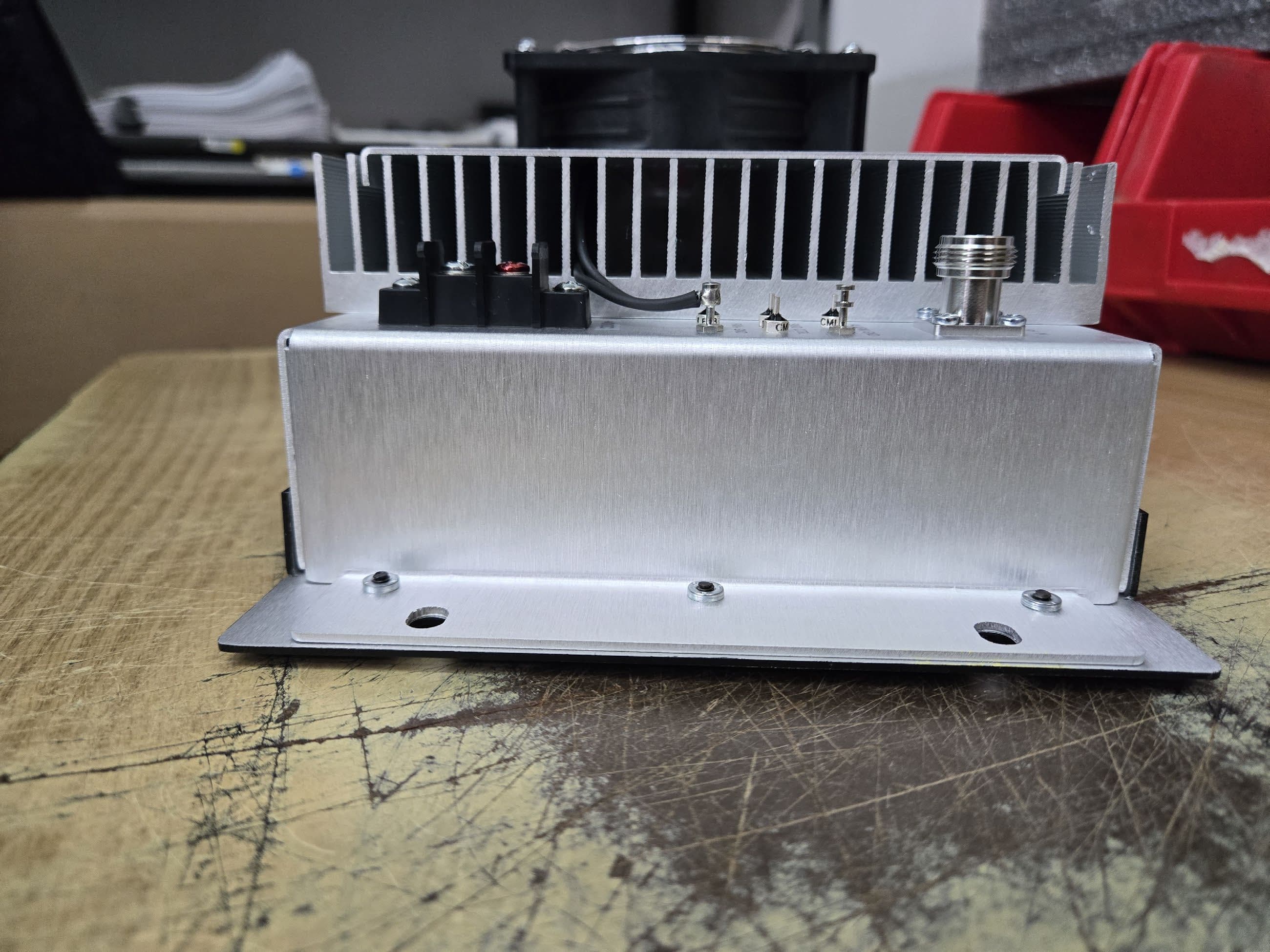
Click to zoom
Application Details
- Equipment Class
- B2I - Part 20 Industrial Booster (CMRS)
- Date of Grant
- Sep 17, 2025
- Application Purpose
- Original Equipment
- Equipment Note
- Power Amplifier AB to C Class
- Frequency Range
- 150.80000000 - 152.85500000
- Company
- Crescend Technologies LLC
- Country
- United States
Documents & Files
Document Text
Text extracted from the exhibit documents filed with the FCC. Open a document above to read the original.
Users Manual
Copyright Crescend Technologies 040003A001 Rev C INSTALLATION AND SERVICE MANUAL C5 Series, 48V Continuous Duty Power Amplifier Crescend Technologies 100 High Grove Blvd Glendale Heights, IL 60139 Phone: 847-908-5400 Fax: 847-908-5408 Email: [email protected] Web Site: www.crescendrf.com Copyright Crescend Technologies 1 040003A015_Rev. C TABLE OF CONTENTS Section 1 Par. No. General Description Page No. 1.1 Introduction 4 1.2 General Description 4 1.3 Functional and Physical Specifications 5 1.4 Equipment Changes 5 Section 2 Installation 2.1 Introduction 8 2.2 Electrical Service Recommendations 8 2.3 Unpacking and Inspection 8 2.4 Installation Instructions 9 2.5 Amplifier Summary Alarm and Power Cutback Control 10 Section 3 General Operating Information 3.1 Introduction 11 3.2 Location of Status Indicators 11 3.3 Initial Start-Up 12 Section 4 Principles of Operation 4.1 Introduction 13 4.2 RF Input Signal 13 4.3 RF Output Load 13 4.4 Functional Description 13 4.4.1 Main RF Path 13 4.4.2 Loop Control 13 4.4.3 VSWR Protection 13 4.4.4 Thermal Protection 13 4.5 Amplifier Cooling 13 Copyright Crescend Technologies 2 040003A015_Rev. C TABLE OF CONTENTS (Continued) Section 5 Par. No. Maintenance Page No. 5.1 Introduction 14 5.2 Periodic Maintenance 14 5.3 Cleaning Air Inlets/Outlets 14 5.4 Test Equipment Required for Test 15 5.5 Performance Test 15 Section 6 Troubleshooting 6.1 Introduction 16 6.2 Troubleshooting 16 6.3 Return for Service Procedure 17 6.3.1 Obtaining an RMA 17 6.3.2 Repackaging for Shipment 17 Figure List of Illustrations 1-1 C5 Series Amplifier, Front View 4 1-2 C5 Series Amplifier, Rear View 5 2-1 C5 Series Amplifier, Rear View Left 9 2-2 C5 Series Amplifier, Rear View Right 9 2-3 C5 Power Cutback Circuit 10 3-1 C5 Series Status Indicators, Front Panel 11 5-1 Amplifier Test Setup diagram 15 Table List of Tables 1-1 C5 Amplifier Functional Specifications 6 1-2 Frequency Ranges, Input/Output Power, Current, Spurious and Harmonics 7 2-1 Summary Alarm and Cutback Control Connections 10 3-1 C5 Series Amplifier Status Indicators 11 5-1 Periodic Maintenance 14 5-2 Test Equipment Required 15 6-1 Troubleshooting 16 7-1 Revision History 17 Copyright Crescend Technologies 3 040003A015_Rev. C 1. GENERAL DESCRIPTION 1.1. INTRODUCTION This manual contains information and procedures for installation, operation, and maintenance of Crescend’s C5 Series Continuous Duty Power Amplifier. The manual is organized into six sections as follows: Section 1. General Description Section 2. Installation Section 3. Operating Instructions Section 4. Principles of Operation Section 5. Maintenance Section 6. Troubleshooting 1.2. PRODUCT DESCRIPTION The Crescend Technologies C5 Series of RF power amplifiers are designed for trunking and conventional repeater applications. Rack mountable and designed to accept a range of input powers for a given rated output power, each amplifier covers a broad range of frequencies without retuning. Closed loop power control is used to maintain a constant output power under varying voltage, signal input, frequency and output load conditions. Several design features work to protect the amplifier under adverse conditions. Designed to fit in 7 inches (4RU) of rack space, the C5 front panel includes status LED indicators for DC and Alarm conditions. RF Input, RF Output, DC, summary alarm and power cutback connections are found on the back of the amplifier. A rear mounted fan brings in air from the back and blows the air across the heat sink fins exiting out the sides of the amplifier. The fan is activated when the unit is powered. Figures 1-1 and 1-2 show front and rear views of the C5 amplifier. Figure 1-1. C5 Series Amplifier, Front View Copyright Crescend Technologies 4 040003A015_Rev. C Figure 1-2. C5 Series Amplifier, Rear View 1.3. FUNCTIONAL AND PHYSICAL SPECIFICATIONS Functional and physical specifications for the C5 Series amplifiers are listed in Tables 1-1 and 1-2. 1.4. EQUIPMENT CHANGES Crescend Technologies, Inc. reserves the right to make minor changes without notice, including, but not necessarily limited to, component substitution and circuitry changes. Such changes may or may not be incorporated in this manual, although it is our intention to keep each manual as up to date as possible. To that end, we ask that you, our customer, share information with us acquired in field situations, which might be of assistance to another user. Copyright Crescend Technologies 5 040003A015_Rev. C Table 1-1. C5 Series Amplifier Functional Specifications Frequency Range: See Table 1-2 (Range Set at Factory) Operating Voltage: +48 ± 1.5 VDC Current Consumption: See Table 1-2 Duty Cycle: 100% Power Input: See Table 1-2 (Range Set at Factory) Power Output (Single Carrier Operation): See Table 1-2 (Range Set at Factory) Input Return Loss: -10 dB (Maximum) Spurious & Harmonics: See Table 1-2 Input/Output Impedance: 50 Ohms (Nominal) Load VSWR Tolerance: VSWR Protected above 2.5:1 (Nominal) Input/Output Connector: Type N Female Vertical Mounting: 7.0 in Horizontal Mounting: 19.0 in Depth: 6.0 in Weight: 10 lbs (4.6 kg) (Nominal) Cooling Method: Fan Forced Air Over Heat Sink Operating Temp. Range: -30°C to +60 °C Storage & Transport: -40 °C to +70 °C Humidity: 80% at +40 °C (Non-Condensing) Altitude: 10,000 Feet (Maximum) Front Panel Display: INDICATORS DC ON (Green) LOW OUTPUT (Red) HIGH VSWR (Red) OVER TEMP (Red) Alarm and Control Pins: SUMMARY ALARM Summary of Low Output, High VSWR, Over Temp Alarms CONTROLS RELAY (Relay) CTRL (Partial Power Cutback) Copyright Crescend Technologies 6 040003A015_Rev. C Table 1-2. Frequency Ranges, Input/Output Power, Current, Spurious and Harmonics Frequency Range (MHz) Input Power Range (W) Rated Output Power (W) Typ Current (A) Max Current (A) Spurious and Harmonics (dBc) 136-174 (DE) 0.1-0.2 0.2-0.5 0.5-1 1-2 2-5 5-10 10-20 20-50 250 (P25) 10.5 12.5 <-70 NOTES: Manufacturer’s Rated Output Power of this Equipment is for Single Carrier Operation. Al…
Text truncated - open the document above for the full version.
Attestation Statements
Headquarters Defense Solutions 100 High Grove Blvd. 1803 Mt. Rose Ave., Bldg. B Glendale Heights, IL 60139 York, PA 17403 www.crescendrf.com P 847 908 5400 P 717 235 5474 [email protected] F 847 908 5408 F 717 227 4444 Federal Communications Commission Authorization and Evaluation Division 7435 Oakland Mills Road Columbia, MD 21046 USA Date: 05-21-2024 Ref: Attestation Statements Part 2.911(d)(7) Filing FCC ID or Grantee Code: CWWP25XXDE4 Applicant: FRN – 0004288767 Crescend Technologies, LLC (“the applicant”) certifies that, as of the date of t he filing of the application, we designate ourselves as the U.S. agent for service of process. Designated U.S. Agent Information: FRN: 0004288767 Company Name: Crescend Technologies, LLC Address: 100 High Grove Blvd, Glendale Heights, IL 60139 Contact Person: James Hougo Tel.: 847-908-5408 Email: [email protected] Sincerely, James A Hougo CEO Crescend Technologies, LLC
Attestation Statements
Headquarters Defense Solutions 100 High Grove Blvd. 1803 Mt. Rose Ave., Bldg. B Glendale Heights, IL 60139 York, PA 17403 www.crescendrf.com P 847 908 5400 P 717 235 5474 [email protected] F 847 908 5408 F 717 227 4444 Federal Communications Commission Authorization and Evaluation Division, 7435 Oakland Mills Road Columbia, MD 21046 USA Re: FCC ID: CWWP25XXDE4 R ef: Attestation Statement per KDB 935210 D02 G entlemen: In accordance with KDB 935210 D02 Signal Boosters Certification v04r02, section V and IV, we, Crescend Technologies, LLC, attests that the warning label messages and Class B disclosure will also be shown in online and point-of -sales marking materials and on the outside packaging of the device. S incerely, Ja mes A Hougo CEO Crescend Technologies, LLC
Attestation Statements
Headquarters Defense Solutions 100 High Grove Blvd. 1803 Mt. Rose Ave., Bldg. B Glendale Heights, IL 60139 York, PA 17403 www.crescendrf.com P 847 908 5400 P 717 235 5474 [email protected] F 847 908 5408 F 717 227 4444 Federal Communications Commission Authorization and Evaluation Division 7435 Oakland Mills Road Columbia, MD 21046 USA Date: 05-21-2024 Ref: Attestation Statements Part 2.911(d)(5)(ii) Filing FCC ID: CWWP25XXDE4 Crescend Technologies, LLC (“the applicant”) certifies that, as of the date of t he filing of the application, the applicant is not identified on the Covered List (as a specifically named entity or any of its subsidiaries or affiliates) as an entity producing “covered” equipment. Sincerely, James A Hougo CEO Crescend Technologies, LLC
Attestation Statements
Headquarters Defense Solutions 100 High Grove Blvd. 1803 Mt. Rose Ave., Bldg. B Glendale Heights, IL 60139 York, PA 17403 www.crescendrf.com P 847 908 5400 P 717 235 5474 [email protected] F 847 908 5408 F 717 227 4444 Federal Communications Commission Authorization and Evaluation Division 7435 Oakland Mills Road Columbia, MD 21046 USA Date: 05-21-2024 Ref: Attestation Statements Part 2.911(d)(5)(i) Filing FCC ID: CWWP25XXDE4 Crescend Technologies, LLC (“the applicant”) certifies that the equipment for which authorization is sought is not “covered” equipment prohibited from receiving an equipment authorization pursuant to section 2.903 of the FCC rules. Sincerely, J ames A Hougo CEO Crescend Technologies, LLC
Cover Letter(s)
March 4, 2024 Timco Engineering, Inc. 13146 NW 86 th Drive, Suite 400 Alachua, FL 32615 SUBJECT: Application for Certification for FCC ID: CWWP25XXDE4 IC: 7291A-P25XXDE4, Model #: P25-10DE4-C5-001 To Whom It May Concern: We, the undersigned, hereby authorize Sharon Hoffman at Timco Engineering Inc. on our behalf, to apply to the Federal Communications Commission and ISED on our equipment. Any and all acts carried out by Sharon Hoffman at Timco Engineering Inc. on our behalf shall have the same effect as acts of our own. This is to advise that we are in full compliance with the Anti-Drug Abuse Act. We, the applicant, are not subject to a denial of federal benefits pursuant to Section 5301 of the Anti-Drug Act of 1988, 21 USC853a, and no party to the application is subject to a denial of federal benefits pursuant to that section. Regards, fa,ff� James A Hougo CEO Crescend Technologies, LLC Headquarters 100 High Grove Blvd. Glendale Heights. IL 60139 P 847 908 5400 F 84 7 908 5408 Defense Solutions 1803 Mt. Rose Ave .. Bldg. B York, PA 17403 www.crescendrf.com P 717 235 5474 [email protected] F 717 227 4444
Cover Letter(s)
Headquarters Defense Solutions 100 High Grove Blvd. 1803 Mt. Rose Ave., Bldg. B Glendale Heights, IL 60139 York, PA 17403 www.crescendrf.com P 847 908 5400 P 717 235 5474 [email protected] F 847 908 5408 F 717 227 4444 Federal Communications Commission Authorization and Evaluation Division, 7435 Oakland Mills Road Columbia, MD 21046 USA Re: FCC ID: CWWP25XXDE4 Gentlemen: This equipment meets the requirements of the FCC Rules, Part 90.203(e) and (g), as applicable. Programming of this product’s transmit frequencies can be performed ONLY by the manufacturer or by service or maintenance personnel. The operator cannot program transmit frequencies using the equipment’s external operation controls. Sincerely, James A Hougo CEO Crescend Technologies, LLC
Cover Letter(s)
AN IIA COMPANY 13146 NW 86 th Drive, Suite 400 Alachua, FL 32615 (352) 472-5500 ● Certification: [email protected] ● Testing: [email protected] ● www.timcoengr.com June 6, 2024 Federal Communications Commission Authorization and Evaluation Division 7435 Oakland Mills Road Columbia, MD 21046 Confidentiality Request regarding application for certification of FCC ID: CWWP25XXDE4 Pursuant to Sections 0.457 and 0.459 of the Commission’s Rules, we hereby request confidential treatment of information accompanying this application as outlined below: Exhibit Type Schematics Block Diagram Parts List Circuit Description Tune Up Procedure The above materials contain trade secrets and proprietary information not customarily released to the public. The public disclosure of these materials may be harmful to the applicant and provide unjustified benefits to its competitors. The applicant understands that pursuant to Section 0.457 of the Rules, disclosure of this application and all accompanying documentation will not be made before the date of the Grant for this application. Pursuant to DA04-1705 June 15, 2004 of the Commission’s public notice, we also request temporary confidential treatment of information accompanying this application as outlined below for 180 Days. Exhibit Type Internal Photos User Manual Sincerely, Sharon Hoffman Agent
External Photos
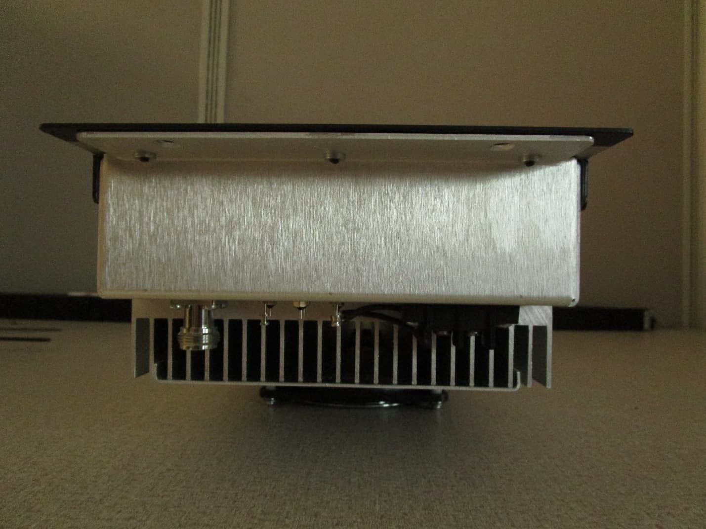
-- Crescend Technologies – Power Amplifier P25-xxDE4-C5-001 Exterior Photos Exterior – Front -- Crescend Technologies – Exterior – Rear -- Crescend Technologies – Exterior – Side Place for FCC Label Exterior – Side
ID Label/Location Info
Crescend Technologies, LLC FCC ID: CWWP25XXDE4 IC: 7291A-P25XXDE4 Label sample and location Label Location
RF Exposure Info
Test Report# TR_12486-24_FCC 1.1310/ MPE_ Revision: 2 Te s t Report - FCC Par t 1.1310/ MPE Applicant: Crescend Technologies, LLC. This test report relates only to the items tested as identified and is not valid for any subsequent changes or modifications made to the equipment under test. 13146 NW 86 th Drive, Suite 400, Alachua, Florida 32615 (352) 472-5500 / [email protected] Page 2 of 10 This test report shall not be reproduced except in full without the written and signed permission of Timco Engineering Inc., a subsidiary of Industrial Inspection & Analysis, Inc. (IIA). Table of Contents 1. APPLICANT INFORMATION ........................................................................................................................................................................... 3 2. LOCATION OF TESTING ................................................................................................................................................................................. 3 2.1 TEST LABORATORY ...................................................................................................................................................................... 3 2.2 TESTING WAS PERFORMED, REVIEWED BY .................................................................................................................................... 4 3. TEST SAMPLE(S) (EUT/DUT) ........................................................................................................................................................................... 5 3.1 DESCRIPTION OF THE EUT .......................................................................................................................................................... 5 4. TEST METHODS & APPLICABLE REGULATORY LIMITS ............................................................................................................................ 6 4.1 TEST METHODS/STANDARDS/GUIDANCE: .................................................................................................................................... 6 4.1.1 FCC Limits for Maximum Permissible Exposure (MPE) .......................................................................................... 6 4.2 EQUATIONS ................................................................................................................................................................................ 7 5. RF EXPOSURE RESULTS .................................................................................................................................................................................. 8 6. HISTORY OF TEST REPORT CHANGES ........................................................................................................................................................ 9 13146 NW 86 th Drive, Suite 400, Alachua, Florida 32615 (352) 472-5500 / [email protected] Page 3 of 10 This test report shall not be reproduced except in full without the written and signed permission of Timco Engineering Inc., a subsidiary of Industrial Inspection & Analysis, Inc. (IIA). 1. Applicant Information Applicant: Crescend Technologies, LLC. Address: 100 High Grove Blvd., Glendale Heights, Illinois, 60139, United States 2. Location of Testing 2.1 Test Laboratory Timco Engineering Inc. is a subsidiary of Industrial Inspection & Analysis, Inc. (“IIA”). Testing was performed at IIA’s permanent laboratory located at 13146 NW 86 th Drive, Suite 400, Alachua, Florida 32615. FCC test firm # 578780 FCC Designation # US1070 FCC site registration is under A2LA certificate # 0955.01 ISED Canada test site registration # 2056A EU Notified Body # 1177 For all designations see A2LA scope # 0955.01 13146 NW 86 th Drive, Suite 400, Alachua, Florida 32615 (352) 472-5500 / [email protected] Page 4 of 10 This test report shall not be reproduced except in full without the written and signed permission of Timco Engineering Inc., a subsidiary of Industrial Inspection & Analysis, Inc. (IIA). 2.2 Testing was performed, reviewed by Dates of Testing: 3/8/2024 – 4/29/2023 Signature: Name & Title: Tim Royer, EMC Engineer Date of Signature 4/1/2024 Signature: Name & Title: Kristoffer Costa, EMC Technician Date of Signature 4/1/2024 13146 NW 86 th Drive, Suite 400, Alachua, Florida 32615 (352) 472-5500 / [email protected] Page 5 of 10 This test report shall not be reproduced except in full without the written and signed permission of Timco Engineering Inc., a subsidiary of Industrial Inspection & Analysis, Inc. (IIA). 3. Test Sample(s) (EUT/DUT) The test sample was received: 3/4/2024 3.1 Description of the EUT A description as well as unambiguous identification of the EUT(s) tested. Where more than one sample is required for technical reasons (such as the use of connected units for the purpose of conducted output power testing where the product units will have integral antennas), each specific test shall identify which unit was tested. Identification FCC ID: CWWP25XXDE4 Brief Description VHF P25 Amplifier Model(s) # P25-10DE4-C5-001 Firmware version N/A Software version N/A Serial Number A-04 Technical Characteristics Frequency Range 150 MHz- 174 MHz RF O/P Power (Max.) 11A, 150-250 W Modulation FM, PM_Flat Envelope Signal Number of Channels N/A Duty Cycle 100% Antenna Connector N Type Voltage Rating (AC or Batt.) 48 VDC Antenna Characteristics Antenna Frequency Range Mode / BW Antenna Gain 1 n/a n/a 0 dBi - Note: Information such as antenna gain, firmware/software numbers are provided by manufacturer and cannot be validated by the test lab. 13146 NW 86 th Drive, Suite 400, Alachua, Florida 32615 (352) 472-5500 / [email protected] Page 6 of 10 This test report shall not be reproduced except in full without the written and signed permission of Timco Engineering Inc., a subsidiary of Industrial Inspection & Analysis, Inc. (IIA). 4. Test methods & Applicable Regulatory Limits 4.1 Test methods/St…
Text truncated - open the document above for the full version.
Test Report
Test Report# TR_12486-24_FCC 90_Booster Class B_ Revision: 2 Test Report - FCC PART 90 Booster Class B (B9B) Applicant: Crescend Technologies, LLC. This test report relates only to the items tested as identified and is not valid for any subsequent changes or modifications made to the equipment under test. 13146 NW 86 th Drive, Suite 400, Alachua, Florida 32615 (352) 472-5500 / [email protected] Page 2 of 54 This test report shall not be reproduced except in full without the written and signed permission of Timco Engineering Inc., a subsidiary of Industrial Inspection & Analysis, Inc. (IIA). Table of Contents 1. APPLICANT INFORMATION ........................................................................................................................................................................... 4 1.1 TEST RESULT SUMMARY .............................................................................................................................................................. 4 2. LOCATION OF TESTING ................................................................................................................................................................................. 6 2.1 TEST LABORATORY ...................................................................................................................................................................... 6 2.2 TESTING WAS PERFORMED, REVIEWED BY .................................................................................................................................... 6 3. TEST SAMPLE(S) (EUT/DUT) ........................................................................................................................................................................... 7 3.1 DEFINITIONS ............................................................................................................................................................................... 7 3.2 DESCRIPTION OF THE EUT .......................................................................................................................................................... 8 3.3 CONFIGURATION OF EUT ........................................................................................................................................................... 9 3.4 TEST SETUP OF EUT ................................................................................................................................................................... 9 4. TEST METHODS & APPLICABLE REGULATORY LIMITS .......................................................................................................................... 10 4.1 TEST METHODS/STANDARDS/GUIDANCE: .................................................................................................................................. 10 4.2 APPLIED LIMITS AND REGULATORY LIMITS: ................................................................................................................................ 10 5. MEASUREMENT UNCERTAINTY .................................................................................................................................................................. 10 6. ENVIRONMENTAL CONDITIONS ............................................................................................................................................................... 10 6.1 TEMPERATURE & HUMIDITY ...................................................................................................................................................... 10 7. LIST OF TEST EQUIPMENT AND TEST FACILITY ....................................................................................................................................... 11 7.1 LIST OF TEST EQUIPMENT .......................................................................................................................................................... 11 8. TEST RESULTS ................................................................................................................................................................................................. 13 8.1 POWER AT THE FINAL AMPLIFIER ............................................................................................................................................... 14 8.2 RF OUTPUT POWER & GAIN ..................................................................................................................................................... 15 8.3 OUT-OF-BAND REJECTION........................................................................................................................................................ 17 8.3.1 Test Plot, Class B ....................................................................................................................................................... 18 8.4 BANDWIDTH & EMISSION ......................................................................................................................................................... 19 8.5 INPUT VS OUTPUT SIGNAL COMPARISON .................................................................................................................................20 8.5.1 12.5 kHz FM, Input Signal ......................................................................................................................................... 22 8.5.2 C4FM, Input Signal .................................................................................................................................................... 23 8.5.3 12.5 kHz, FM, Mask D, AGC, 150.82 MHz ............................................................................................................... 24 8.5.4 12.5 kHz, FM, Mask D, AGC+3, 150.82 MHz .......................................................................................................... 25 8.5.5 C4FM, Mask D, AGC, 150.82 MHz .....................................…
Text truncated - open the document above for the full version.
Test Setup Photos
ANNEX B – Test Setup Photograph Exhibit Crescend Technologies, LLC. FCC ID: CWWP25XXDE4 Conducted Test Setup Radiated Testing, Table Setup (15.109) Radiated Testing, Table Setup #1 (Pt 90) Radiated Testing, Table Setup #2 (Pt 90) Radiated Testing, Below 1 GHz #1 (Pt 15.109) Radiated Test Setup, 30 – 1000 MHz Radiated Testing, Below 1 GHz #1 (Pt 15.109) Radiated Testing, Below 1 GHz #2 (Pt 90) Radiated Testing, Above 1 GHz (Pt 15.109) Radiated Testing, Above 1 GHz (Pt 90) Noise Testing (Pt 90)
Contact Information
Applicant
James Hougo(President)
[email protected]Fax: 847-908-5408
Test Firm
IIA LAB SERVICES, LLCBruno Clavier
[email protected]Fax: 352 472 2030
Technical Specifications
| # | Rule Parts | Frequency Range | Power Output | Emission | Tolerance |
|---|---|---|---|---|---|
| 1 | 22H | 150.8 MHz - 152.855 MHz | 250 W | F3E | Amp |
| 2 | 22H | 161.575 MHz - 161.775 MHz | 250 W | F3E | Amp |
| 3 | 22H | 150.8 MHz - 152.855 MHz | 250 W | F1E | Amp |
| 4 | 22H | 161.575 MHz - 161.775 MHz | 250 W | F1E | Amp |
| 5 | 22H | 150.8 MHz - 152.855 MHz | 250 W | F1D | Amp |
| 6 | 22H | 161.575 MHz - 161.775 MHz | 250 W | F1D | Amp |
Other Applications from Crescend Technologies LLC
CWWP10XXDE1
Mar 10, 2020VHF AMPLIFIER
Equipment Class
B9B - Part 90 Class B Industrial Booster (non-SMR)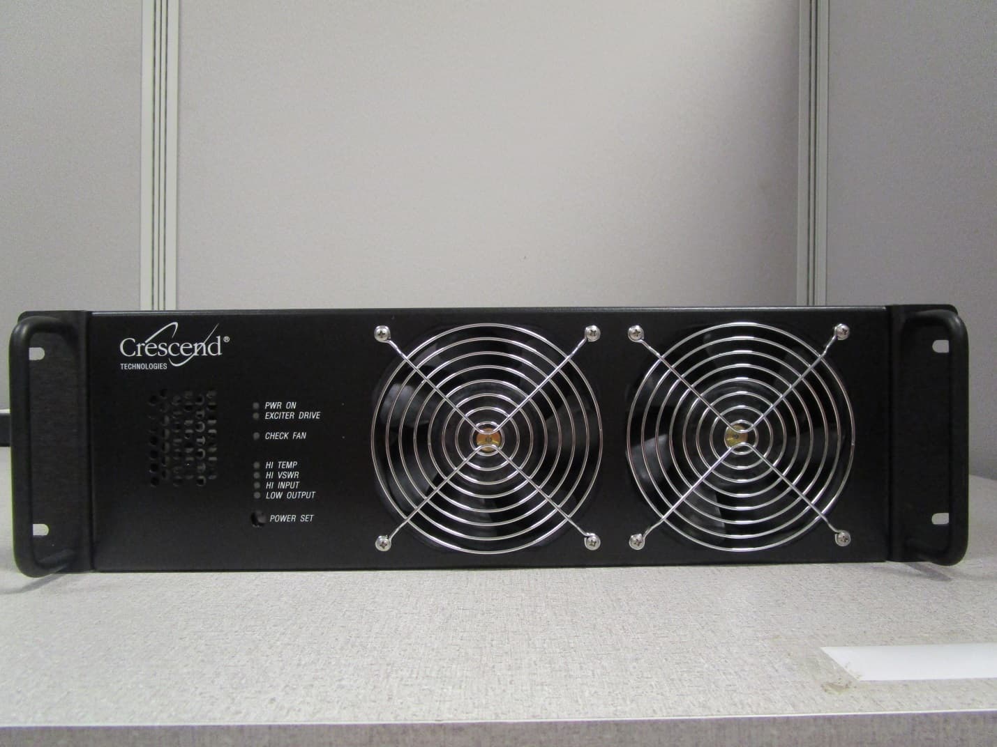
CWWP25XXHA3
Jan 27, 2020HIGH BAND HIGH POWER AMPLIFIER
Equipment Class
B9A - Part 90 Class A Industrial Booster (non-SMR)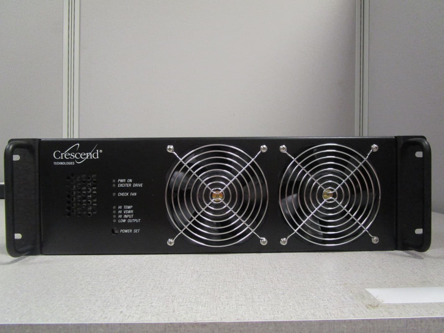
CWWP25XXGA3
Jan 21, 2020LOW BAND HIGH POWER AMPLIFIER
Equipment Class
B9A - Part 90 Class A Industrial Booster (non-SMR)
CWWP2RTK450
May 10, 201525Watt One-Way Amplifier
Equipment Class
AMP - Amplifier
CWWDSDTV100XX
Mar 03, 2014100W VHF MOBILE AMPLIFIER
Equipment Class
AMP - Amplifier