CWWP2RTK45025Watt One-Way Amplifier
Crescend Technologies LLC
Click to zoom
Application Details
- Equipment Class
- AMP - Amplifier
- Date of Grant
- May 10, 2015
- Application Purpose
- Original Equipment
- Date of Application
- May 10, 2015
- Equipment Note
- 25Watt One-Way Amplifier
- Frequency Range
- 450.00000000 - 470.00000000
- Company
- Crescend Technologies LLC
- Country
- United States
Documents & Files
Document Text
Text extracted from the exhibit documents filed with the FCC. Open a document above to read the original.
Users Manual
Crescend P2-RTK-450 Power Amplifier User Manual 1. General Information The P2-RTK-450 is a AB class power amplifier (PA), intended to work with UHF RTK positioning systems, amplifying phase modulated signals. PA has the automatic gain control (AGC) loop. The gain value is set up in the factory. PA is protected against the load mismatch and overheating. It is also protected against excessive DC power supply voltage and DC voltage reversed polarity (for short time). PA has a current limiter, which threshold goes down in the case of overheating. PA provides LED indication of normal and alarm modes, as well as the combined alarm signal. PA contains an externally controlled by-pass line, activated either when the power supply voltage is removed, or when the special pin “SH/D” is pulled to the ground. There is a forced air cooling system, working when the unit is in the amplifying mode. The general parameters of RTK-450 in the normal operation mode are listed below: Frequency range of operation (f), MHz . . . . . . . . . . . . . . . . . . . . . . . . . . . . . . 450 - 470; Input power (Pin), W . . . . . . . . . . . . . . . . . . . . . . . . . . . . . . . . . . . . . . . . . . . . . 0.4 – 2.0; Input return loss, dB, not less than . . . . . . . . . . . . . . . . . . . . . . . . . . . . . . . . . . . . . . . 10; Gain in the normal operation (G), dB, nominal . . . . . . . . . . . . . . . . . . . . . . . . . . . . . . 11; Bypass insertion loss, dB, not greater than . . . . . . . . . . . . . . . . . . . . . . . . . . . . . . . . . 1.0; DC power supply voltage (Vsup), V - nominal . . . . . . . . . . . . . . . . . . . . . . . . . . . . . . . . . . . . . . . . . . . . . . . . . . 13.8; - working range . . . . . . . . . . . . . . . . . . . . . . . . . . . . . . . . . . . . . . . 12.0 – 17.0; DC current (Io), A, not greater than - in amplifying mode . . . . . . . . . . . . . . . . . . . . . . . . . . . . . . . . . . . . . . . . . . . 6.5; - in quiescent mode . . . . . . . . . . . . . . . . . . . . . . . . . . . . . . . . . . . . . . . . . . . 1.8; - in by-pass mode . . . . . . . . . . . . . . . . . . . . . . . . . . . . . . . . . . . . . . . . . . . 0.002; Working ambient temperature range, ºC . . . . . . . . . . . . . . . . . . . . . . . . . . . . . . -30 to +60; Threshold of overheat protection activation: heat sink temperature, ºC . . . . . .. + (85 + 5); RF connectors . . . . . . . . . . . . . . . . . . . . . . . . . . . . . . . . . . . . . . . . . . . . . . 50 Ohm, N (F); DC connectors . . . . . . . . . . . . . . . . . . . . . . . . . . . . . . . . . . . . . . . . . . screws # 6-32 AWG. 2. Construction The unit is intended for installation in a standard 19” cabinet rack, where it takes 4U (7.0”) in the vertical direction. Its depth does not exceed 5”. There are four LED at the front panel that indicate the status of unit operation. There are two N connectors, DC block, four pins (filters) and two ground poles at the rear of chassis. Also, the fan is placed over the heatsink at the rear. 2 3. Installation Unit installation shall provide proper air access to the unit; no obstacle for air is allowed closer than 3” from fan. Unit shall be protected against the direct solar light and precipitation. The air inlets and outlets should be checked every 30 days and cleaned if necessary. If the equipment is operated in a severe dust environment, it should be checked and cleaned more often. If dust and dirt are allowed to accumulate, the cooling efficiency will be diminished. Using either compressed air or a brush with soft bristles, loosen and remove accumulated dust and dirt from the air inlet panels. Check that the fans are running smoothly. A slow running or noisy fan may indicate an imminent fan failure. Heat is one of the biggest factors in reducing the reliability of the amplifier. Ensure the fan has access to cool and clean airflow within the rack. Copper wires # 12 AWG shall be use in DC power line. Wires shall be crimped to ring terminals. Pre-tinning of crimps is recommended. Use # 18 or # 20 AWG wire for unit status monitoring circuit. Connect this wire to the pin “ALARM”. Use # 18 or # 20 AWG wire for forced switching to by-pass mode circuit. Connect this wire to the pin “SH/D”. Make sure all connections are constructed and implemented properly with best practices. Make sure that DC power supply voltage and RF source frequency and power are in the mentioned above limits and that the DC polarity is correct before applying DC power to the amplifier. Notes: - The reversed DC polarity protection circuit may not operate longer than 0.3 sec; - Input power shall not exceed 3 W in the working frequency range and shall not exceed 0.3 W out of th e specified frequency range of operation. 4. Operation Green LED “DC ON” is on and fan is running when DC power supply voltage is applied to the unit, its value does not exceed 17 V and pin “Sh/D” is not connected to the ground. Red LED “LOW OUTPUT” is on if gain is less than 6 dB or input power is less than 0.1 W. Red LED “HIGH VSWR” is on when the load VSWR exceeds 2:1. Red LED “HIGH TEMP” is on when the heat sink temperature reaches +(85 + 5)ºC. The voltage at filter “ALARM” is about 0.5 V less than power supply voltage during normal operation and drops to 0.3V or less when any of mentioned above red LEDs turn on. If a 2 kOhm resistor is connected between this filter and the ground, a TTL compatible output is created. When switching the PA to the by-pass mode, the resistance between pin “SH/D” and ground shall be less than 100 Ohm, or, if a transistor key is used, the voltage drop on the key shall not exceed 0.2 V. The current, coming out from pin “SH/D” does not exceed 1.7 mA. 5. FCC RF Exposure Requirements CAUTION: This transmitter must be restricted to work related operations in a Controlled RF exposure environment. All qualified end-users of this device must have the knowledge to control their exposure conditions and/or duration, and the exposure conditions …
Text truncated - open the document above for the full version.
External Photos
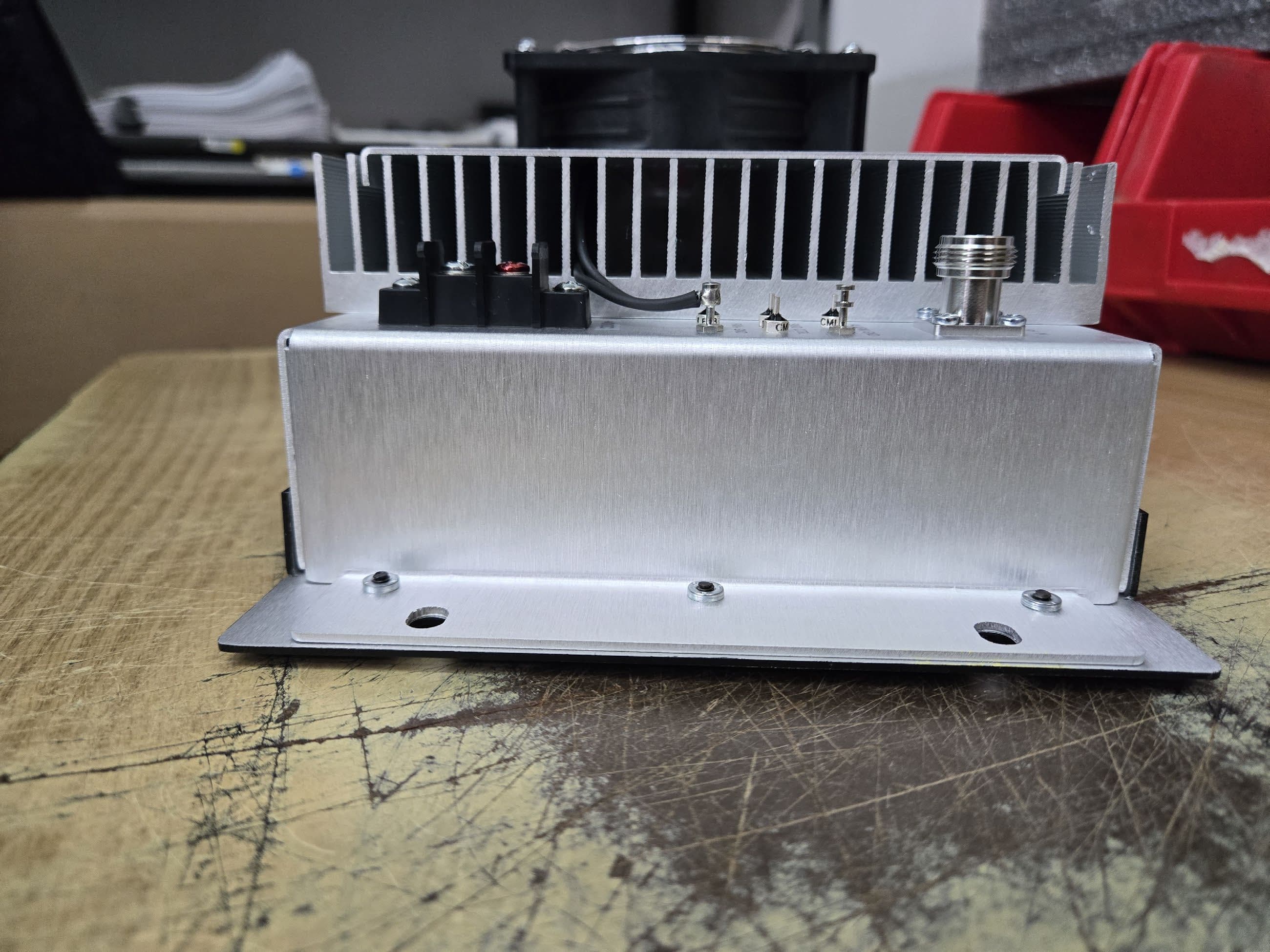
Unit – side view 4 Unit – back view
External Photos
Unit – side view 1 Unit – side view 2 Unit – side view 3
ID Label/Location Info
Crescend TechnologiesSN: xxxxxxxxx Model: P2-RTK-450Pin: 0.4 - 2W PN: xxxxxxxxxxxxxPout: 5 - 25W FCC ID: CWWP2RTK450Freq: 450 - 470 MHz IC: 7291A – P2RTK450Voltage: 13.8 VDC
ID Label/Location Info
Place of Label
Internal Photos
Main Board – top view Main Board – bottom view Indicator Board – top view Indicator Board – bottom view Unit – inside view
RF Exposure Info
RF Exposure Evaluation Report APPLICANT CRESCEND TECHNOLOGIES, LLC 140 E. State Parkway SCHAUMBURG IL 60173 USA FCC ID CWWP2RTK450 IC 7291A-P2RTK450 MODEL NUMBER P2-RTK-450 PRODUCT DESCRIPTION 25W ONE-WAY AMPLIFIER STANDARD APPLIED CFR 47 Part 2.1091 PREPARED BY Sid Sanders We, TIMCO ENGINEERING, INC. would like to declare that the device has been evaluated in accordance with 47 CFR Part 2.1091 and meets the requirements. The attached report shall not be reproduced except in full without the written approval of TIMCO ENGINEERING, INC. 849 NW STATE ROAD 45 NEWBERRY, FL 32669 USA PH: 888.472.2424 OR 352.472.5500 FAX: 352.472.2030 EMAIL: [email protected] HTTP://WWW.TIMCOENGR.COM Applicant: CRESCEND TECHNOLOGIES, LLC FCC ID: CWWP2RTK450 Report: C\CRESCEND_CWW\820AUT15\820AUT15TestReport.docxt Page 2 of 4 GENERAL REMARKS Attestations This equipment has been evaluated in accordance with the standards identified in this report. To the best of my knowledge and belief, these evaluations were performed using the procedures described in this report. I attest that the necessary evaluations were made, under my supervision, at: Timco Engineering Inc. 849 NW State Road 45 Newberry, Fl 32669 Authorized Signatory Name: Sid Sanders Engineering Project Manager Date: 5/7/2015 RF Exposure Requirements General information Device type: 25W ONE-WAY AMPLIFIER Devices that operate under Part 90 of this chapter are subject to RF exposure evaluation prior to equipment authorization or use. Antenna The manufacturer does not specify an antenna, but a typical antenna has a gain of 0 dBi. Configuration Antenna p/n Type Max. Gain (dBi) Fixed mounted Any omni 0 Operating configuration and exposure conditions: The conducted output power is shown in the table below. Typical use qualifies for a maximum duty cycle factor of 100%. Operation: A typical installation consists of an antenna system with a 10 meter coaxial cable of the type RG 213/ U type which has a loss as follows; Nom. Attenuation for RG 213/U: Frequency MHz Attenuation per 100ft. dB 1 .27 10 .55 50 1.3 100 1.9 200 2.7 400 4.1 700 6.5 900 7.6 1000 8.0 4000 21.5 MPE Calculation: The minimum separation distance is calculated as follows: Applicant: CRESCEND TECHNOLOGIES, LLC FCC ID: CWWP2-RTK-450 Report: C\CRESCEND_CWW\820AUT15\820AUT15TestReport.docx The limit for general uncontrolled exposure environment is shown in FCC rule Part 1.11310, Table 1. Max Power 25 W equalsMax Power 25000mW Duty Cycle 100%equalsDuty Factor1 numeric Antenna Gain3 dBi equalsGain numeric1.995262numeric Coax Loss 1.5dB Gain - Coax Loss1.412538 numeric Power Density 0.31 mW/cm 2 Frequency 470MHz Frequency rangPower denEnter this value MHz mW/cm 2 mW/cm 2 0.3-1.34100100 1.34-30 180/f 2 0.0 30-300 0.20.2 300-1,500 f/15000.3 1,500-100,000 11 f = frequency in MHz Minimum Separation Distance95cm0.95 m Minimum Seperation in Inches37.45576 Inches Minimum Separation Distance for Mobile or Fixed Devices General Population/Uncontrolled Exposure Insert values in yellow highlighted boxes to determine Minimum Separation Distance Enter power Density from the chart to the rightRule Part 1.1310, Table 1
Test Report
AMPLIFIER FCC Part 90 & IC RSS-131 TEST REPORT Applicant CRESCEND TECHNOLOGIES, LLC Address 140 E. State Parkway SCHAUMBURG IL 60173 USA FCC ID CWWP2RTK450 IC LABEL 7291A-P2RTK450 Model Number P2-RTK-450 Product Description 25W ONE-WAY AMPLIFIER Standards Applied CFR 47 Part 90 IC Standard RSS-131, Issue 2, July 2003 IC Standard RSS-GEN, Issue 4, November 14 Date Sample Received 4/30/2015 Date Report Issued 5/6/2015 Date Tested 5/1/2015 Tested By Sid Sanders Approved By Cory Leverett Test Results PASS FAIL Report Number Version Number Description Issue Date 820AUT15TestReport.docx Rev.1 Initial Issue 5/6/2015 THE ATTACHED REPORT SHALL NOT BE REPRODUCED EXCEPT IN FULL WITHOUT THE WRITTEN APPROVAL OF TIMCO ENGINEERING, INC. 849 NW STATE ROAD 45 NEWBERRY, FL 32669 USA PH: 888.472.2424 OR 352.472.5500 FAX: 352.472.2030 EMAIL: [email protected] HTTP://WWW.TIMCOENGR.COM Applicant: CRESCEND TECHNOLOGIES, LLC FCC ID: CWWP2RTK450 IC: 7291A-P2RTK450 Report: C\CRESCEND_CWW\820AUT15\820AUT15TestReport.docx Page 2 of 19 TABLE OF CONTENTS GENERAL REMARKS........................................................................................ 3 EUT DESCRIPTION ......................................................................................... 4 TEST REPORT SUMMARY ................................................................................ 5 TEST RESULTS ............................................................................................... 6 RF POWER OUTPUT ............................................................................................................ 6 SPURIOUS EMISSIONS AT ANTENNA TERMINALS (CONDUCTED) .................................... 14 SPURIOUS EMISSIONS AT ANTENNA TERMINALS (CONDUCTED) .................................... 15 SPURIOUS EMISSIONS AT ANTENNA TERMINALS (CONDUCTED) .................................... 16 FIELD STRENGTH OF SPURIOUS EMISSIONS - RADIATED .......................... 17 EQUIPMENT LIST .......................................................................................... 19 Applicant: CRESCEND TECHNOLOGIES, LLC FCC ID: CWWP2RTK450 IC: 7291A-P2RTK450 Report: C\CRESCEND_CWW\820AUT15\820AUT15TestReport.docx Page 3 of 19 GENERAL REMARKS The attached report shall not be reproduced except in full without the written permission of Timco Engineering Inc. Summary The device under test does: Fulfill the general approval requirements as identified in this test report Not fulfill the general approval requirements as identified in this test report Attestations This equipment has been tested in accordance with the standards identified in this test report. To the best of my knowledge and belief, these tests were performed using the measurement procedures described in this report. All instrumentation and accessories used to test products for compliance to the indicated standards are calibrated regularly in accordance with ISO 17025 requirements. I attest that the necessary measurements were made, under my supervision, at: Timco Engineering Inc. 849 NW State Road 45 Newberry, FL 32669 Authorized Signatory Name: Sid Sanders Engineering Project Manager Date: 5/6/2015 Table of Contents Applicant: CRESCEND TECHNOLOGIES, LLC FCC ID: CWWP2RTK450 IC: 7291A-P2RTK450 Report: C\CRESCEND_CWW\820AUT15\820AUT15TestReport.docx Page 4 of 19 EUT DESCRIPTION EUT Description 25W ONE-WAY AMPLIFIER FCC ID CWWP2RTK450 IC 7291A-P2RTK450 Model Number P2-RTK-450 Operating Frequency 450 to 470MHz Test Frequencies 450.025, 460, & 469.075 MHz Type of Emission F1D Modulation C4FM EUT Power Source 110–120Vac/50– 60Hz DC Power 12V Battery Operated Exclusively Test Item Prototype Pre-Production Production Type of Equipment Fixed Mobile Portable Test Conditions The temperature was 24 - 26ºC with a relative humidity of 50 - 65 %. Revision History to the EUT None Test Exercise The EUT was operated in a normal mode. Requirements FCC CFR 47 PART 90, IC STANDARD RSS-131 ISS.2 Test Standards ANSI/TIA 603-D:2010, ANSI C63.4: 2003 , RSS- 131 I.2 Iss. 2 Test Facility Timco Engineering Inc. at 849 NW State Road 45 Newberry, FL 32669 USA. Table of Contents Applicant: CRESCEND TECHNOLOGIES, LLC FCC ID: CWWP2RTK450 IC: 7291A-P2RTK450 Report: C\CRESCEND_CWW\820AUT15\820AUT15TestReport.docx Page 5 of 19 TEST REPORT SUMMARY Rule Part No. Scope of Work Status Pass/Fail/NA Part 2.1033(c)(8), Part 2.1046(a), Part 90 RSS-131 Para. 6.2 RF Power Output PASS RSS-131 Para. 4.2 20dB PASSBAND PASS RSS-131 Para. 6.3.3 99% BANDWIDTH PASS RSS-131 Para. 6.3. BANDWIDTH NON-LINEARITY: PASS Part 2.1033(c) (4) Part 2.1047(a)(6) Modulation Characteristics PASS 2.1051(a) RSS-131Para 6.4 Antenna Conducted Emissions PASS 2.1053, Part 90 Field Strength Spurious Emissions PASS Table of Contents Applicant: CRESCEND TECHNOLOGIES, LLC FCC ID: CWWP2RTK450 IC: 7291A-P2RTK450 Report: C\CRESCEND_CWW\820AUT15\820AUT15TestReport.docx Page 6 of 19 TEST RESULTS RF POWER OUTPUT Rule Part No.: Pt 2.1046(a), Pt 90.205, Pt 90.210, RSS-131 Requirements: Pt 2.1046(a), Pt 90, Pt 90.210, RSS-131 Para. 6.2 & 4.3.2 Method of Measurement: The RF power output was measured at the antenna feed point using a Average power meter. A 50-ohm, resistive wattmeter was connected to the RF output connector. With a nominal battery voltage, and the transmitter properly adjusted the RF output measures: Test Data: Power = 42.16 Watts DC Power Consumption Vdc = 13.6 Ic = 3.1 Frequency MHz Input dBm Output dBm Output W Gain dB 450 34.08 43.90 24.5 9.8 460 34.36 44.4 27.5 9.84 470 34.71 44.76 29.91 10.05 Gain Variation in Passband Rule Part No.; RSS – 131 Para. 6.1 Requirement: The passband Gain shall not exceed the Nominal gain by more than 1.0dB. Results: Less than 0.76dB. Table of Contents RF Power Meter Transmitter Attenuator Transmitter Under Test Modulation Source Power Supply Applicant: CRESCEND TECHNOLOGIES, LLC FCC ID: CWWP2RTK450 IC: 7291A-P2RTK450 Report: C\CRESCEND_CWW\820AUT15\820AUT15TestReport.docx Page 7 of 19 PASS BAND 20dB BANDWIDTH: Requirements:…
Text truncated - open the document above for the full version.
Contact Information
Applicant
James Hougo(President)
Technical Contact
Timco Engineering, Inc.Sid Sanders
[email protected]888-472-2424
849 NW State Road 45 · Newberry, Florida · United States
Non-Technical Contact
Timco Engineering, Inc.Sharon Hoffman
[email protected]888-472-2424
Test Firm
Timco Engineering, Inc.Bruno Clavier
Technical Specifications
| # | Rule Parts | Frequency Range | Power Output | Emission | Tolerance |
|---|---|---|---|---|---|
| 2 | 9 | 450 MHz - 470 MHz | 5 W | F1D | Amp |
Other Applications from Crescend Technologies LLC
CWWP25XXDE4
Sep 17, 2025Power Amplifier AB to C Class
Equipment Class
B2I - Part 20 Industrial Booster (CMRS)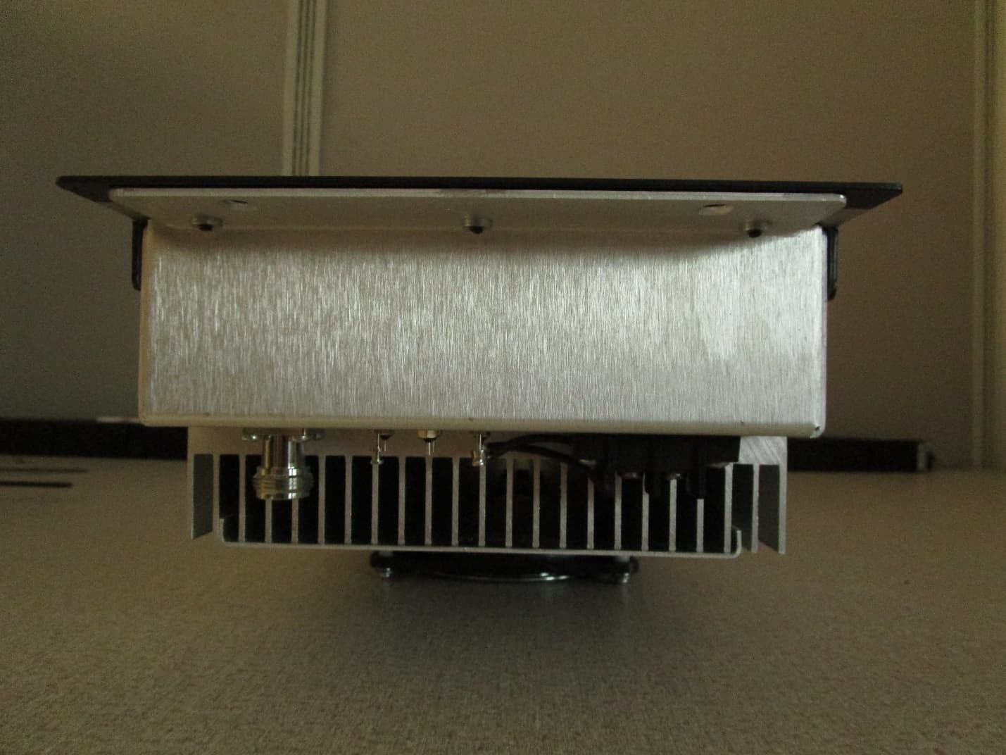
CWWP10XXDE1
Mar 10, 2020VHF AMPLIFIER
Equipment Class
B9B - Part 90 Class B Industrial Booster (non-SMR)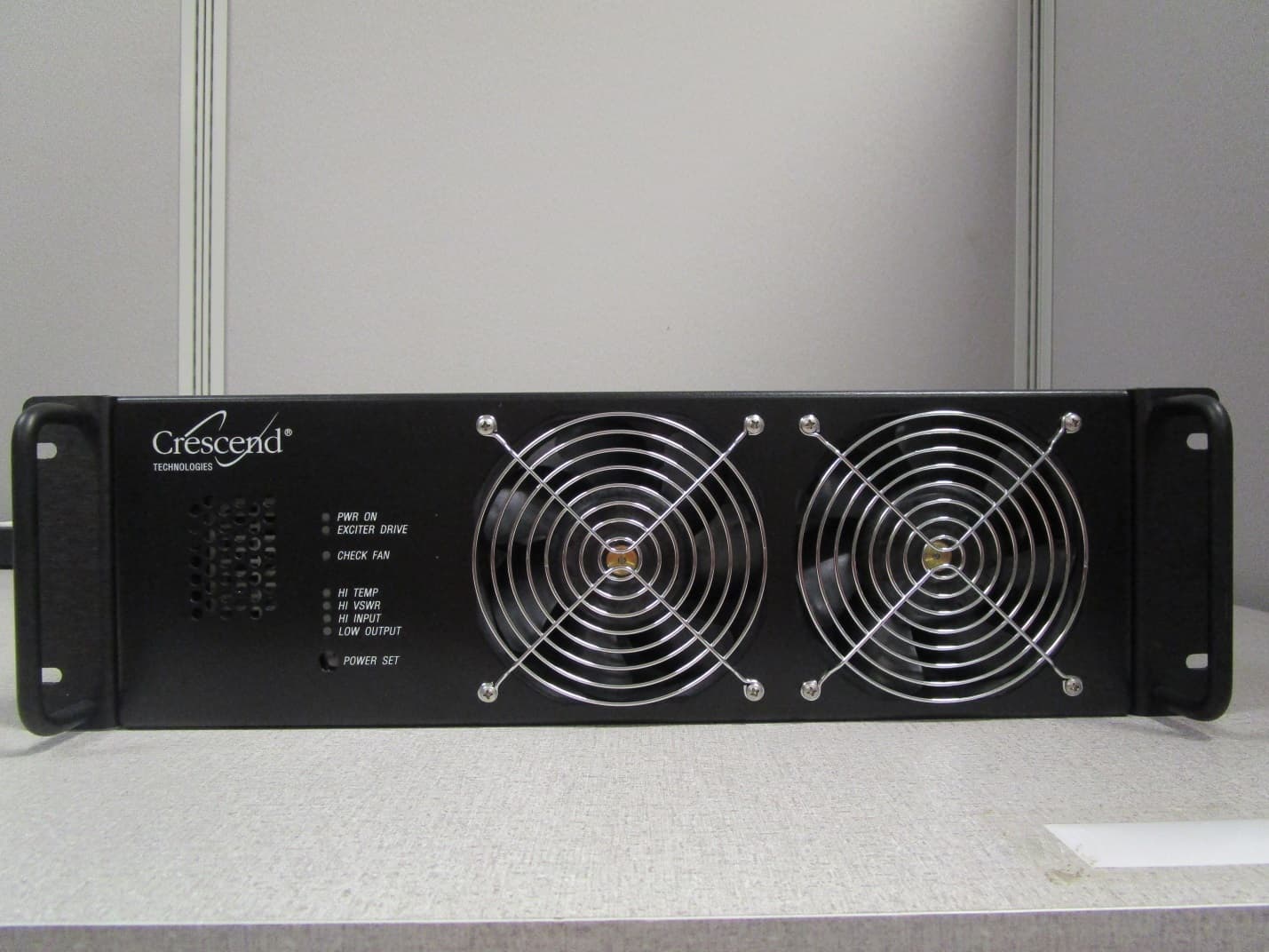
CWWP25XXHA3
Jan 27, 2020HIGH BAND HIGH POWER AMPLIFIER
Equipment Class
B9A - Part 90 Class A Industrial Booster (non-SMR)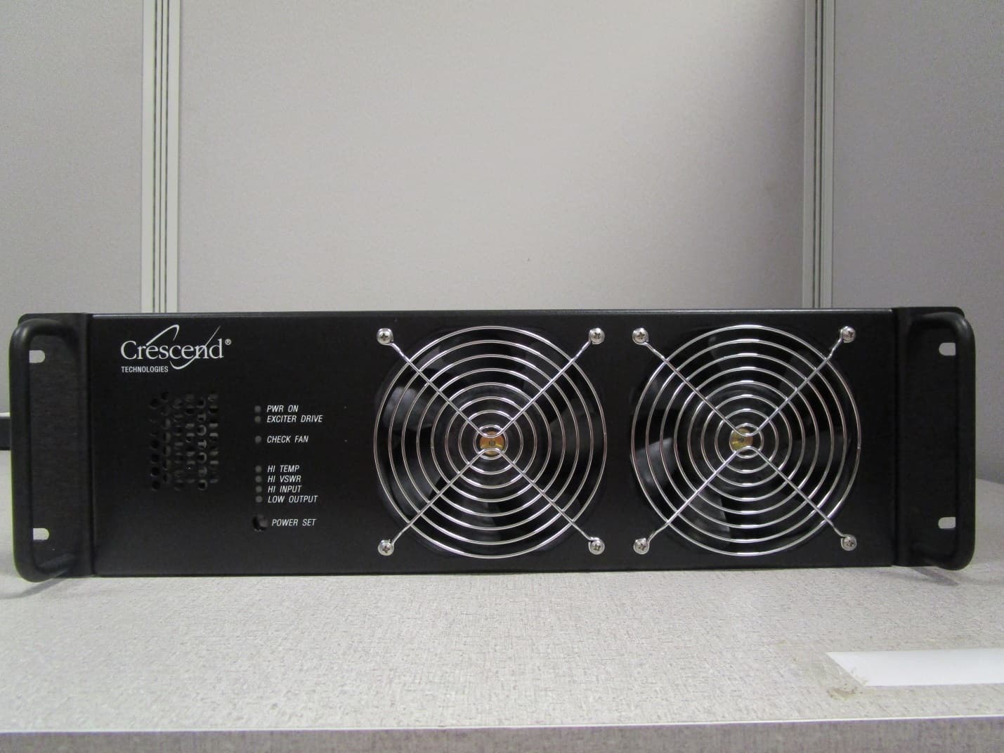
CWWP25XXGA3
Jan 21, 2020LOW BAND HIGH POWER AMPLIFIER
Equipment Class
B9A - Part 90 Class A Industrial Booster (non-SMR)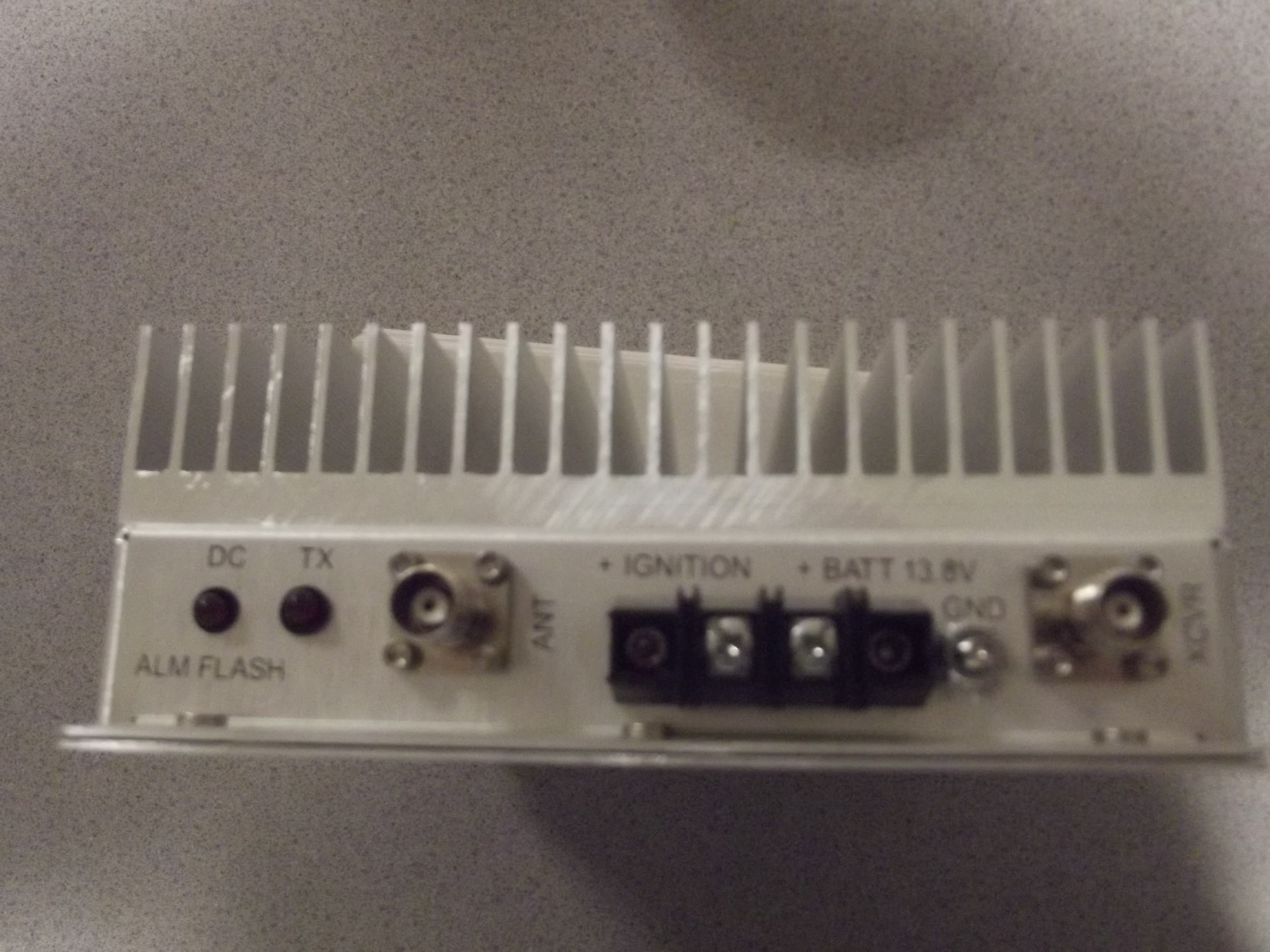
CWWDSDTV100XX
Mar 03, 2014100W VHF MOBILE AMPLIFIER
Equipment Class
AMP - Amplifier