CWWDSDTV100XX100W VHF MOBILE AMPLIFIER
Crescend Technologies LLC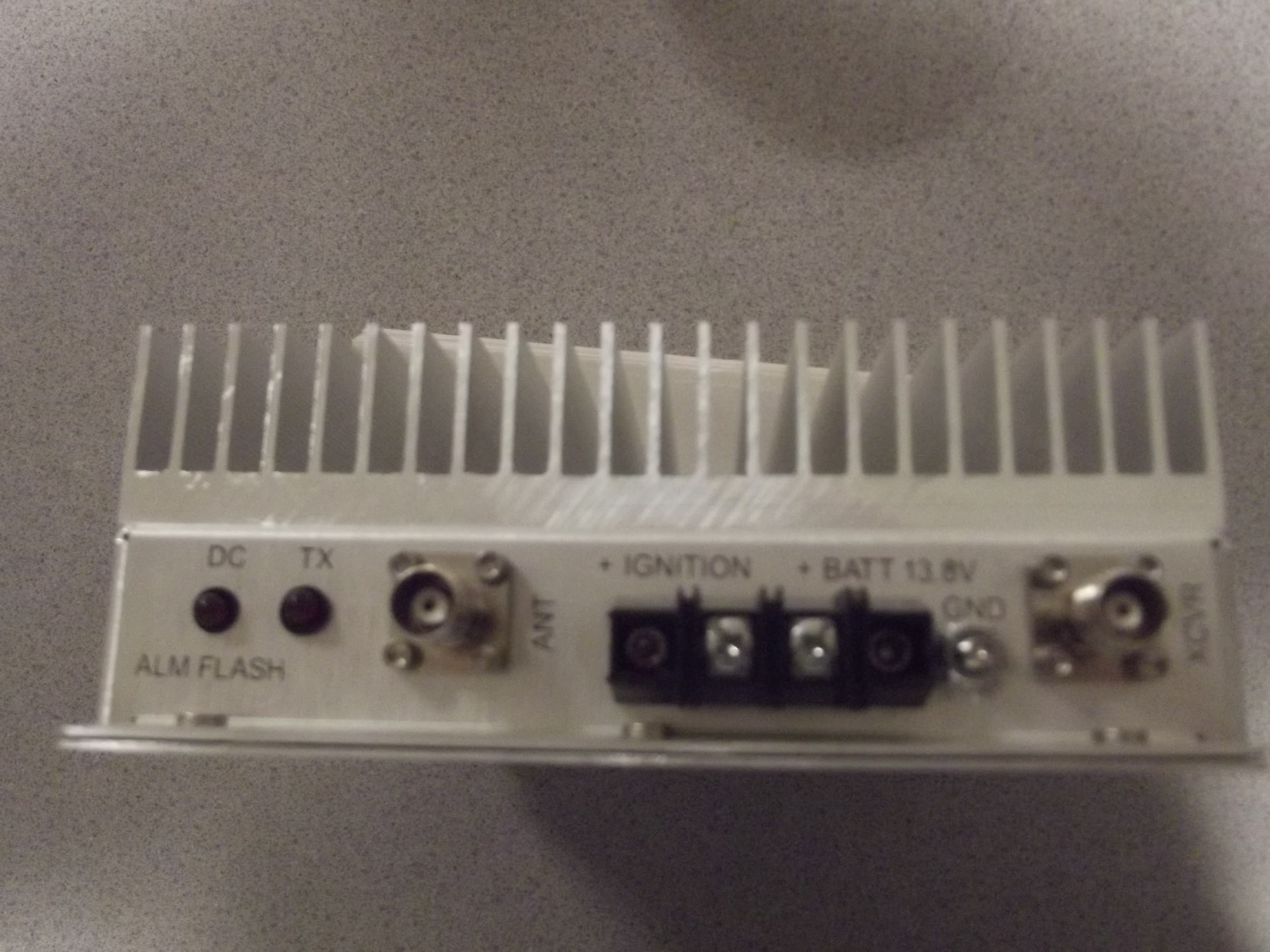
Click to zoom
Application Details
- Equipment Class
- AMP - Amplifier
- Date of Grant
- Mar 03, 2014
- Application Purpose
- Original Equipment
- Date of Application
- Mar 03, 2014
- Equipment Note
- 100W VHF MOBILE AMPLIFIER
- Frequency Range
- 157.18750000 - 157.45000000
- Company
- Crescend Technologies LLC
- Country
- United States
Documents & Files
Document Text
Text extracted from the exhibit documents filed with the FCC. Open a document above to read the original.
Users Manual
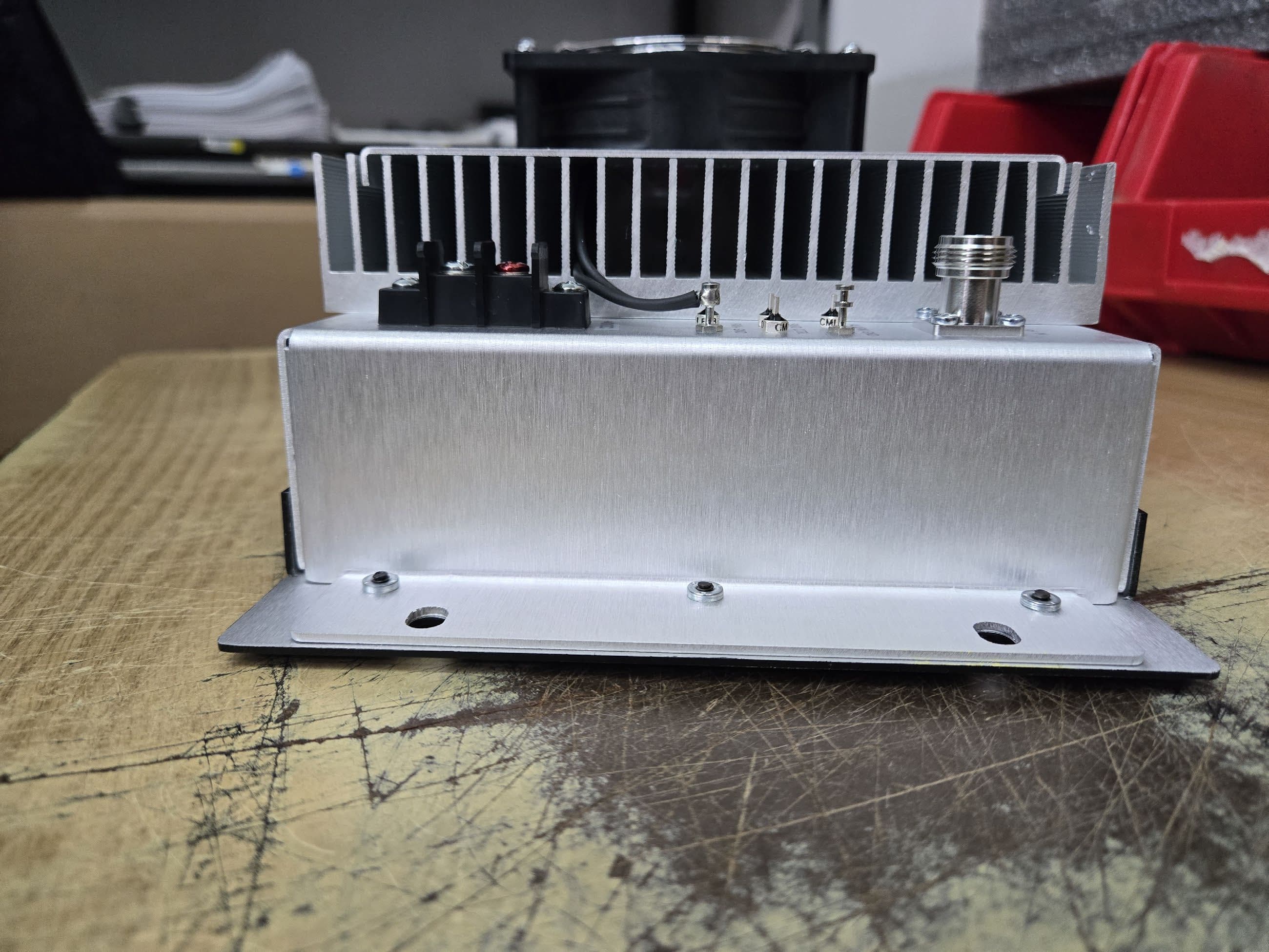
User Manual: DSDTV100XX VHF Mobile Power Amplifier 1. General Information This is a 100W mobile VHF amplifier. It is intended for amplification of single carrier phase (frequency) modulated narrowband signals in the 136-174 MHz frequency range. The input power is divided into several ranges. Be sure to operate within the specified range. PIN diode switching is used to switch between transmit and receive. 2. Construction The unit is assembled in the chassis with heatsink, intended for convection cooling (see Fig 2). Unit dimensions are 2.8” x 6.8” x 9.8”. 2 3. Installation Install the unit in one of two positions, showed at the right side of Fig. 2: vertical or horizontal. The proper air access to the unit shall be provided: no obstacle for air is allowed closer than 3” from heatsink. Also, make sure that status LED can be monitored. Screws from # 10 to # 1/4-20 are recommended. See the fastening holes positions in Fig. 3. Use copper wires # 10 AWG shall be used for connecting to clamps “+ BATT” and “GND”. Use copper wire from # 16 AWG to # 12 may by used for connecting to clamp “+ IGNITION”. Wires shall be crimped for making ring terminals. Connect the clamp “GND” to the car nearest ground screw of suitable size. Connect the clamp “+ BATT” to the pole “+” of car battery. Use 30 A fuse for protection. Connect the clamp “+ IGNITION” to the output of car ignition key that is able to provide not less than 8 V and not less than 3 mA when it is keyed on. Use 0.5 A fuse for protection. Use 50 Ohm coax cables with THC (M) connectors for connecting to “XCVR” and “ANT” . Connect the port “XCVR” to RF output of radio. Connect the port “ANT” to antenna. 4. Operation - LED “DC” goes on continuously, when the car ignition key is ON position; - LED “TX” goes on continuously, when the RF input power is greater ~1/3 of minimum rated level (see Table 1); - The continuous transmit time should not exceed 2 min, and the duty cycle should not be greater than 25% to avoiding overheating; - In the case of overheating (the heatsink temperature reaches +85ºC) the unit switches to RX mode, and LED “DC” starts flashing (independently of input power); - If the load VSWR exceeds 2-3:1, the output power reduces, and LED “DC” starts flashing, when RF signal is applied to the input.' 3 5. Warning Statements FCC Part 15.21 Warning Statement- NOTE: THE GRANTEE IS NOT RESPONSIBLE FOR ANY CHANGES OR MODIFICATIONS NOT EXPRESSLY APPROVED BY THE PARTY RESPONSIBLE FOR COMPLIANCE. SUCH MODIFICATIONS COULD VOID THE USER’S AUTHORITY TO OPERATE THE EQUIPMENT. FCC Part 15.19 Warning Statement- (Required for all Part 15 devices) THIS DEVICE COMPLIES WITH PART 15 OF THE FCC RULES. OPERATION IS SUBJECT TO THE FOLLOWING TWO CONDITIONS: (1) THIS DEVICE MAY NOT CAUSE HARMFUL INTERFERENCE, AND (2) THIS DEVICE MUST ACCEPT ANY INTERFERENCE RECEIVED, INCLUDING INTERFERENCE THAT MAY CAUSE UNDESIRED OPERATION. FCC Part 90.203(e) Compliance This radio complies with 47 CFR Part 90.203(e) in that the operator cannot program and transmit on frequencies, other than those stated by the manufacturer, service or maintenance personnel, using the equipment's external operation controls. It is noted that the FCC rules would be violated if this radio is used to operate on frequencies outside of FCC (Part 90 and Part 22) Frequency Bands for users other than the (Federal Government). FCC RF Exposure Requirements CAUTION: This transmitter must be restricted to work related operations in a Controlled RF exposure environment. All qualified end-users of this device must have the knowledge to control their exposure conditions and/or duration, and the exposure conditions and/or duration of their passengers and bystanders, to comply with the General Population / Uncontrolled MPE limit and requirements. Vehicle – Antenna Installation Instructions The antenna(s) used for this transmitter must be installed to provide a separation distance of at least 1.8m from all persons, must not be co-located or operating in conjunction with any other antenna or transmitter, and must not exceed an antenna gain of 0 dBi with a minimum cable loss of 1dB. The antenna used for this transmitter must be mounted on the center of the roof ONLY and must be installed in vehicle having the following characteristics in order to prevent bystanders or passengers from being exposed to levels exceeding the limits set for General Population/Uncontrolled Exposure environment: 4 · All passengers must be sitting under a solid metal roof · Rooftop width must be at least 153.5 inches (or 3.9m) OR the edges of the physical boundary of the vehicle must be at least 3.9m apart. Failure to observe these restrictions will result in exceeding the FCC RF exposure limits. IC RSS-GEN, Sec 7.1.2 Warning Statement- (Required for Transmitters) ENGLISH: Under Industry Canada regulations, this radio transmitter may only operate using an antenna of a type and maximum (or lesser) gain approved for the transmitter by Industry Canada. To reduce potential radio interference to other users, the antenna type and its gain should be so chosen that the equivalent isotropically radiated power (e.i.r.p.) is not more than that necessary for successful communication. FRENCH: Conformément à la réglementation d'Industrie Canada, le présent émetteur radio peut fonctionner avec une antenne d'un type et d'un gain maximal (ou inférieur) approuvé pour l'émetteur par Industrie Canada. Dans le but de réduire les risques de brouillage radioélectrique à l'intention des autres utilisateurs, il faut choisir le type d'antenne et son gain de sorte que la puissance isotrope rayonnée quivalente (p.i.r.e.) ne dépassepas l'intensité nécessaire à l'établissement d'une communication satisfaisante. IC RSS-102, Sec 2.6 Warning Statements ENGLISH: The applicant is responsible for providing proper instructions to the user of the radio device, and any usage restrictions, including limits of exposure durations. The user manual shall provide installation and …
Text truncated - open the document above for the full version.
Cover Letter(s)
920 E. State Parkway • Schaumburg, IL 60173 Toll Free Number: (800) USA MADE (800.872.6233) Phone: 847.908.5400 • Fax: 847.908.5408 www.crescendtech.com • E-mail: [email protected] January 15, 2014 Federal Communications Commission Authorization and Evaluation Division Confidentiality Request regarding application for certification of FCC ID: CWWDSDTV100XX Pursuant to Sections 0.457 and 0.459 of the Commission’s Rules, we hereby request confidential treatment of information accompanying this application as outlined below: Schematic Schematics DSDTV100XX.pdf Block Diagram Block Diagram DSDTV100XX.pdf Parts List Semiconductor List DSDTV100XX.pdf Operational Description Description DSDTV100XX.pdf Test Tune Procedure Test Procedure DSDTV100XX.pdf Semiconductor List Semiconductor List DSDTV100XX.pdf The above materials contain trade secrets and proprietary information not customarily released to the public. The public disclosure of these materials may be harmful to the applicant and provide unjustified benefits to its competitors. Pursuant to DA 04-1705 June 15, 2004 of the Commission’s public notice, we also request temporary confidential treatment of information accompanying this application as outlined below: Internal Photos Internal Photo DSDTV100XX.pdf External Internal Photos External Photos DSDTV100XX.pdf User Manual User Manual DSDTV100XX.pdf Sincerely, Mark Obermann
ID Label/Location Info
Crescend Technologies SN: xxxxxxxxx Model: DSDTV Series VHF Pin: xx PN: xxxxxxxxxxxxx Pout: xx FCC ID: CWWDSDTV100XX Freq: xx IC: 7291A – DSDTV100XX Voltage: xx
ID Label/Location Info
PLACE FOR THE WARNING LABEL
RF Exposure Info
849 NW State Road 45 • P. O. Box 370 • Newberry, Florida 32669 USA Telephone (352) 472-5500 • (888) 472-2424 • FAX (352) 472-2030 • email: [email protected] RF Exposure Requirements Applicant: Crescend Technologies, LLC FCC ID: CWWDSDTV100XX General information Device type: Part 90 RF amplifier designed to increase the RF output power of a mobile push to talk type of radio. Device category: Mobile Mobile devices that operate under Part 90 of this chapter are subject to RF exposure evaluation prior to equipment authorization or use. Antenna The manufacturer does not specify an antenna, but a typical mobile mounted antenna has a gain of 0 dBi. Configuration Antenna p/n Type Max. Gain (dBi) mobile mounted Any omni 0 Operating configuration and exposure conditions: The conducted output power is 100 Watts. Typical use qualifies for a maximum duty cycle factor of 100%. - Mobile operation: A typical installation consists of an antenna system with a coaxial cable of the type RG 213/ U type which has a loss of 1dB for a length of 30 feet at VHF frequencies. MPE Calculation: The minimum separation distance is calculated as follows: The limit for general population/uncontrolled exposure environment below 300 MHz is 0.2 mW/cm 2 . 849 NW State Road 45 • P. O. Box 370 • Newberry, Florida 32669 USA Telephone (352) 472-5500 • (888) 472-2424 • FAX (352) 472-2030 • email: [email protected] The conducted power output is 100 watt. The coax loss was taken as 1 dB. Antenna gain was taken as 0 dBi 100% duty cycle Uncontrolled environment G = 1 (0dBi) P = 50dBm – cable loss (1dB) = 49dBm = 79.4W Limit = 27.5 V/m d = √(30 x 1 x 79.4) ÷ 27.5 = 1.77m 1.77m rounded up to 1.8m for a 100% duty cycle Conclusion: The antenna(s) used for this transmitter must be installed to provide a separation distance of at least 1.8m from all passengers and bystanders. Prepared by: Richard Block Timco Engineering Inc.
Test Report
FCC PT 90 AMPLIFIER AND IC RSS-131 (i2) , RSS-GEN (i3) TEST REPORT Applicant CRESCEND TECHNOLOGIES, LLC Address 140 E. State Parkway SCHAUMBURG IL 60173 USA FCC ID CWWDSDTV100XX IC LABEL 7291A-DSDTV100XX Model Number DSDTV SERIES 100XX Product Description 100W VHF MOBILE AMPLIFIER Standards Applied CFR 47 Part 90, Part 22 IC Standard RSS-131, Issue 2, July 2003 IC Standard RSS-GEN, Issue 3, December 2010 Date Sample Received 1/17/2014 Date Tested 1/21/2014 Date Report Issued 1/27/2014 ‘Tested By NAM NGUYEN Approved By NAM NGUYEN Timco Report No. 94AUT14TestReport Test Results PASS FAIL THE ATTACHED REPORT SHALL NOT BE REPRODUCED EXCEPT IN FULL WITHOUT THE WRITTEN APPROVAL OF TIMCO ENGINEERING, INC. 849 NW STATE ROAD 45 NEWBERRY, FL 32669 USA PH: 888.472.2424 OR 352.472.5500 FAX: 352.472.2030 EMAIL: [email protected] HTTP://WWW.TIMCOENGR.COM TABLE OF CONTENTS GENERAL REMARKS ...................................................................................... 3 FCC PART RULES ........................................................................................... 4 TEST ENVIRONMENT ..................................................................................... 4 TEST SETUP SUMMARY ................................................................................. 4 EUT DESCRIPTION ......................................................................................... 5 TEST EQUIPMENT .......................................................................................... 6 TEST PROCEDURES ....................................................................................... 7 TEST RESULTS ............................................................................................... 9 RF POWER OUTPUT ........................................................................................................... 9 INPUT/OUTPUT COMPARISON ......................................................................................... 10 OCCUPIED BANDWIDTH .................................................................................................. 15 ANALOG SIGNAL INPUT ................................................................................................................................ 16 DIGITAL SIGNAL INPUT ................................................................................................................................. 19 SPURIOUS EMISSIONS AT ANTENNA TERMINALS (CONDUCTED) .................................... 22 FIELD STRENGTH OF SPURIOUS EMISSIONS (RADIATED) ............................................... 24 POWER LINE CONDUCTED INTERFERENCE .................................................................... 26 PASSBAND GAIN AND 20 dB BANDWIDTH ....................................................................... 27 Applicant: CRESCEND TECHNOLOGIES, LLC FCC ID: CWWDSDTV100XX IC: 7291A-DSDTV100XX MODEL #: DSDTV SERIES 100XX Report: C\CRESCEND_CWW\94AUT14\94AUT14TestReport Page 2 of 28 GENERAL REMARKS The attached report shall not be reproduced except in full without the written permission of Timco Engineering Inc. Summary The device under test does: fulfill the general approval requirements as identified in this test report not fulfill the general approval requirements as identified in this test report Attestations This equipment has been tested in accordance with the standards identified in this test report. To the best of my knowledge and belief, these tests were performed using the measurement procedures described in this report. All instrumentation and accessories used to test products for compliance to the indicated standards are calibrated regularly in accordance with ISO 17025 requirements. I attest that the necessary measurements were made, under my supervision, at: Timco Engineering Inc. 849 NW State Road 45 Newberry, Fl 32669 Authorized Signatory Name: Nam Nguyen Engineering Project Manager Date: 1/24/2014 Applicant: CRESCEND TECHNOLOGIES, LLC FCC ID: CWWDSDTV100XX IC: 7291A-DSDTV100XX MODEL #: DSDTV SERIES 100XX Report: C\CRESCEND_CWW\94AUT14\94AUT14TestReport Page 3 of 28 FCC PART RULES Applicable Rule(s) ANSI/TIA 603-C: 2004 CFR 47 Part 90, Part 22 IC Standard RSS-131, Issue 2, July 2003 IC Standard RSS-GEN, Issue 3, December 2010 TEST ENVIRONMENT Test Facility Timco Engineering, Inc. 849 NW State Road 45 Newberry, FL 32669 USA. Test Condition in the laboratory Temperature: 26ºC Relative humidity: 50% TEST SETUP SUMMARY Test Setup Diagram/ Description The DUT was placed on the turntable per setup per ANSI C63.4: 2003. A test set up explanation and photo is provided in each test section of this report for clarification. Deviation from the standard/procedure No deviation Modification to the DUT No modification was made Applicant: CRESCEND TECHNOLOGIES, LLC FCC ID: CWWDSDTV100XX IC: 7291A-DSDTV100XX MODEL #: DSDTV SERIES 100XX Report: C\CRESCEND_CWW\94AUT14\94AUT14TestReport Page 4 of 28 EUT DESCRIPTION EUT Description This is a 100W mobile VHF power amplifier. The amplifier is a nonlinear AB/C Class unit that is intended for frequency (phase) modulated (manipulated) signals amplifications. FCC ID CWWDSDTV100XX IC 7291A-DSDTV100XX Model Number DSDTV SERIES 100XX Operating Frequency (136 – 174) MHz Max. Output Power 50.0 dBm (100W) Modulation N/A - Amplifier EUT Power Source 110–120Vac/50– 60Hz DC Power 13.8V Battery Operated Exclusively Test Item Prototype Pre-Production Production Type of Equipment Fixed Mobile Portable Applicant: CRESCEND TECHNOLOGIES, LLC FCC ID: CWWDSDTV100XX IC: 7291A-DSDTV100XX MODEL #: DSDTV SERIES 100XX Report: C\CRESCEND_CWW\94AUT14\94AUT14TestReport Page 5 of 28 TEST EQUIPMENT Device Manufacturer Model Serial Number Cal/Char Date Due Date 3-Meter Semi- Anechoic Chamber Panashield N/A N/A 12/31/13 12/31/15 Antenna: Biconnical Eaton 94455-1 1057 06/14/13 06/14/15 Antenna: Double- Ridged Horn/ETS Horn 2 ETS-Lindgren 3117 00041534 10/05/12 10/05/14 Antenna: Log- Periodic Electro-Metrics LPA-25 1122 05/09/13 05/09/15 Aud…
Text truncated - open the document above for the full version.
Test Setup Photos
RADIATED EMISSIONS FINAL TEST SETUP PHOTOS DUT Final Measurement Setup DUT Power Supply Setup Anechoic Chamber Setup
Contact Information
Applicant
James Hougo(President)
Test Firm
Timco Engineering, Inc.Bruno Clavier
Technical Specifications
| # | Rule Parts | Frequency Range | Power Output | Emission | Tolerance |
|---|---|---|---|---|---|
| 5 | 9 | 157.1875 MHz - 157.45 MHz | 100 W | F3D | Amp |
Other Applications from Crescend Technologies LLC
CWWP25XXDE4
Sep 17, 2025Power Amplifier AB to C Class
Equipment Class
B2I - Part 20 Industrial Booster (CMRS)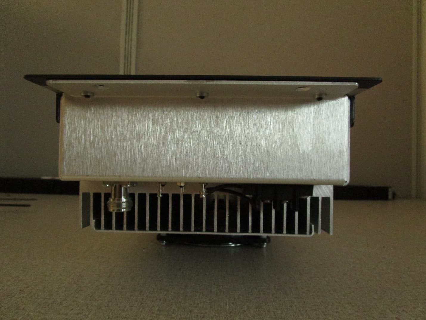
CWWP10XXDE1
Mar 10, 2020VHF AMPLIFIER
Equipment Class
B9B - Part 90 Class B Industrial Booster (non-SMR)
CWWP25XXHA3
Jan 27, 2020HIGH BAND HIGH POWER AMPLIFIER
Equipment Class
B9A - Part 90 Class A Industrial Booster (non-SMR)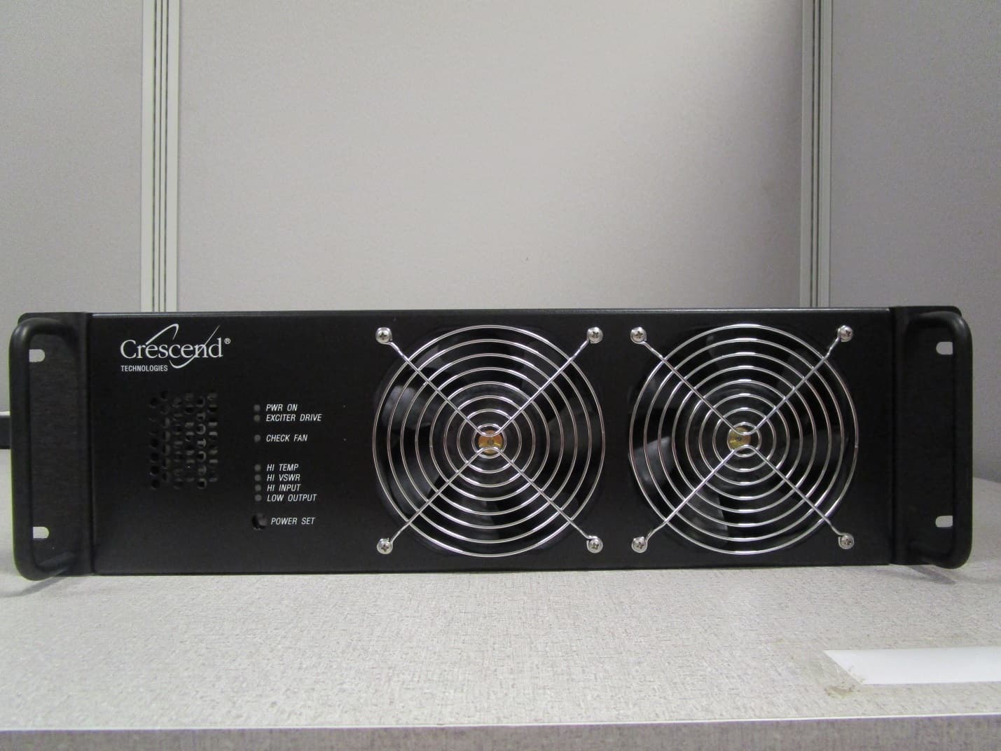
CWWP25XXGA3
Jan 21, 2020LOW BAND HIGH POWER AMPLIFIER
Equipment Class
B9A - Part 90 Class A Industrial Booster (non-SMR)
CWWP2RTK450
May 10, 201525Watt One-Way Amplifier
Equipment Class
AMP - Amplifier