CWWP15XXJK1AMPLIFIER
Crescend Technologies LLC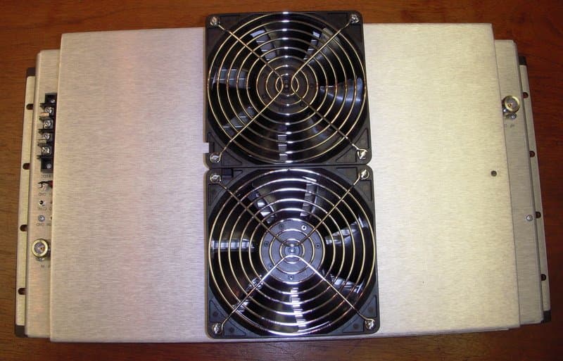
Click to zoom
Application Details
- Equipment Class
- AMP - Amplifier
- Date of Grant
- Sep 06, 2010
- Application Purpose
- Original Equipment
- Date of Application
- Sep 06, 2010
- Equipment Note
- AMPLIFIER
- Frequency Range
- 851.00000000 - 870.00000000
- Company
- Crescend Technologies LLC
- Country
- United States
Documents & Files
Document Text
Text extracted from the exhibit documents filed with the FCC. Open a document above to read the original.
Users Manual
Crescend C6 JK and L Power Amplifier User’s Manual 1. General Information. Power Amplifier (PA) is the C-class unit. It is intended for amplification of single carrier phase (frequency) modulated (manipulated) narrowband signals. Working frequency range lies between 764 MHz and 870 MHz for JK unit (CWWP15XXJK1) and between 890 MHz and 942 MHz for L unit (CWWP15XXL1). Code “xx” shows the input power range: Code: R1 R2 R5 1 2 5 10 20 Range, W: 0.1-0.2 0.2-0.5 0.5-1.0 1.0-2.0 2.0-5.0 5.0-10 10-20 20-50 In the normal operating mode the minimum output power is 150 W for JK and 140 W for L unit. Input VSWR is not greater than 1.7:1. PA meets all FCC requirements to harmonic and spurious levels. The nominal power supply voltage is 13.8VDC. DC current consumption does not exceed 44A for K and 42A for L unit at 13.8V Working ambient temperature range lies from -30 ºC to +60ºC. Input and output power levels are set up in the factory. Customer has an opportunity to reduce the output power, adjusting the special trimmer resistor in the unit, or picking up the value of outer resistor, connected to PA control pin. PA has automatic power control loop that provides the stability of output power during the normal operation and all necessary changes of power in the case of load mismatch or unit overheating. PA is intended for rack mounting in the standard 19” cabinet. The front panel is 10” high. The deepness of unit does not exceed 5”. Four LED at the front panel indicate the status of unit operation. The hole in the side wall gives an access to the trimmer resistor, which allows reducing the output power against the set value. There are two N connectors at the back of chassis. There is power filtering DC connector at the back of chassis with four # 6-32 screws: 2 for “+” pole and 2 for “-“ pole. There are 3 filters at the back of chassis that bring alarming signal, as well signals for the outside power control. Two fans at the back side of unit perform the forced air cooling. Fans start rotating, when RF signal comes to the unit input. 2. Installation Guide. 2.1. Unit installation shall provide a proper air access to the unit; no obstacle for air is allowed closer than 3” from fans. 2.2. Copper wires # 10 AWG shall be use in DC power line. Wires shall be crimped to ring terminals. Two parallel wires shall be use for each pole. Put terminal under PI-shape shunts of DC connector. Do not remove shunts! 3. Operation Guide 3.1. Power supply voltage shall be in the range 13.8 V + 1.0 V. 3.2. The input power inside the working frequency range shall be within the listed above limits. It is prohibit applying any RF signal out of the working frequency range with a power, greater than 10% of the minimum rated one. 3.3. Green LED “DC ON” is on, when DC voltage is applied to the unit. 3.4. Red LED “LOW POWER” is on, when the output power drops below 80% - 85% of set level. In majority of cases it warns about of inside problem. However, the output power may fail due to high load VSWR (in that case LED tells that the power decrease is stronger, then it is needed for VSWR protection). 3.5. Red LED “HIGH VSWR” is on, when the load VSWR exceeds 2.4 – 3. The output power is reduced. 3.6. Red LED “HIGH TEMP” is on, when the heatsink temperature is over +85 ̊C. Then the unit operates with output power, reduced to about 75% of rated one. Fans are running continuously, no matter, is RF drive applied or not. 3.7. Voltage at filter “ALARM” is about 9.5V during the normal unit operation and drops to less than 0.5V, when any of mentioned above red LED goes on. If 1.8 kOhm resistor is connected between this filter and the ground, TTL compatible output is created. 3.8. It is possible to significantly reduce the output power, pulling filter “SH/D” to the ground. However, it is possible to change the output power smoothly by a trimmer resistor (50 kOhm is the recommended value of it), connected between this pin and the ground. 3.9. The output power drops to about 75% of rated level, if the filter “CTRL” is pulled to the ground.
External Photos
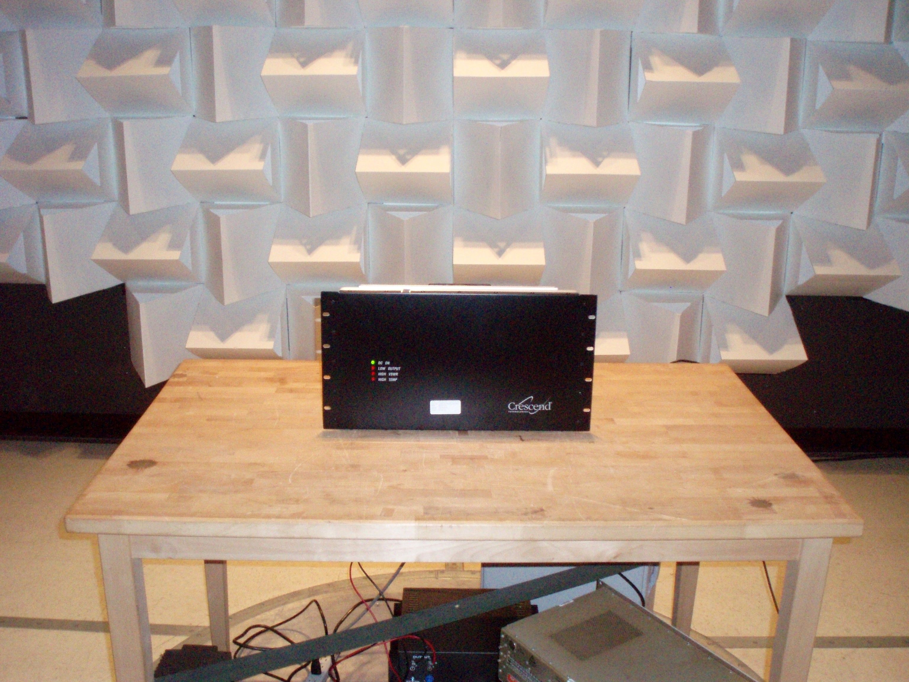
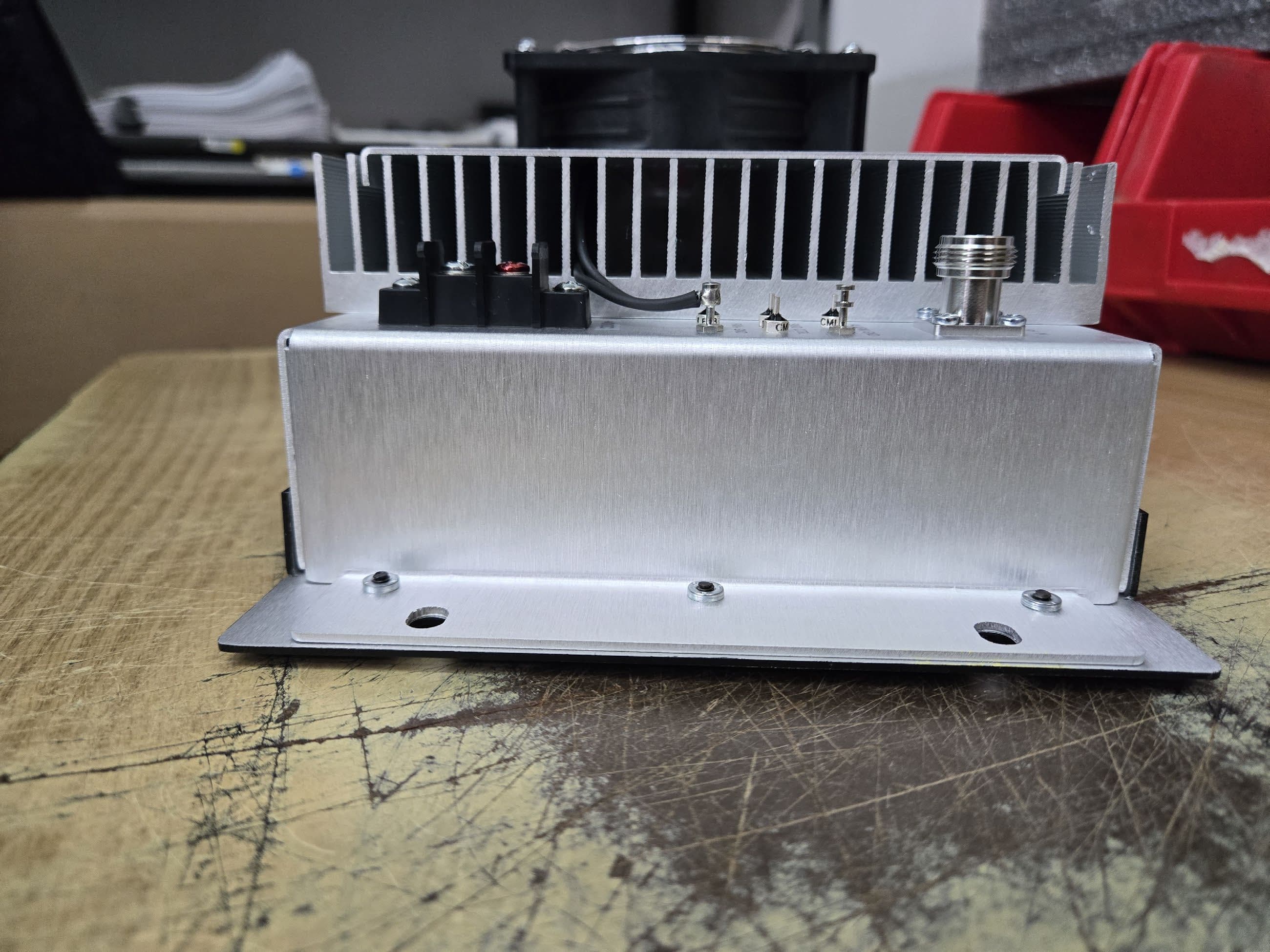
Exterior - Front Exterior - Rear Exterior - Side
ID Label/Location Info
C6: Places for Labels (3 total) This page was created using Nitro PDF SDK trial software. To purchase, go to http://www.nitropdf.com/
Internal Photos
Amplifier Photos Interior Top Side – All PCBs Note: With the exception of the controller and indicator boards, all other boards have a ground plane on the back side (no traces or components). Bottom Side – Controller Board Bottom Side – Indicator Board
Test Report
FCC PT 90 AMPLIFIER AND IC RSS-119, RSS-GEN TEST REPORT APPLICANT CRESCEND TECHNOLOGIES, LLC ADDRESS 920 EAST STATE PARKWAY SCHAUMBURG IL 60173 USA FCC ID FCC ID: CWWP15XXJK1 IC LABEL IC: 7291A-P15XXJK1 MODEL NUMBER P15 SERIES 700/800 PRODUCT DESCRIPTION AMPLIFIER DATE SAMPLE RECEIVED 3/2/2010 DATE TESTED 3/19/2010 TESTED BY Nam Nguyen APPROVED BY Mario de Aranzeta TIMCO REPORT NO. 461AUT10TestReport.pdf TEST RESULTS PASS FAIL THE ATTACHED REPORT SHALL NOT BE REPRODUCED EXCEPT IN FULL WITHOUT THE WRITTEN APPROVAL OF TIMCO ENGINEERING, INC. 849 NW STATE ROAD 45 NEWBERRY, FL 32669 USA PH: 888.472.2424 OR 352.472.5500 FAX: 352.472.2030 EMAIL: [email protected] HTTP: //WWW.TIMCOENGR.COM Certificate # 0955-01 Applicant: CRESCEND TECHNOLOGIEDS LLC FCC ID: CWWP15XXJK1 IC: 7291A- P15XXJK1 MODEL #: P15 Series 700/800 Report: C\CRESCEND_CWW\461AUT10\461AUT10TestReport.doc Page 2 of 18 TABLE OF CONTENTS GENERAL REMARKS ...................................................................................... 3 REPORT SUMMARY ........................................................................................ 4 TEST ENVIRONMENT AND TEST SETUP......................................................... 4 DUT DESCRIPTION......................................................................................... 5 TEST EQUIPMENT .......................................................................................... 6 TEST PROCEDURES ....................................................................................... 7 TEST RESULTS............................................................................................... 9 RF POWER OUTPUT ............................................................................................................. 9 OCCUPIED BANDWIDTH .................................................................................................... 14 SPURIOUS EMISSIONS AT ANTENNA TERMINALS (CONDUCTED) ..................................... 15 FIELD STRENGTH OF SPURIOUS EMISSIONS (RADIATED)................................................ 16 POWER LINE CONDUCTED INTERFERENCE ..................................................................... 17 AMPLIFIER RESPONSE PLOT ....................................................................... 18 Applicant: CRESCEND TECHNOLOGIEDS LLC FCC ID: CWWP15XXJK1 IC: 7291A- P15XXJK1 MODEL #: P15 Series 700/800 Report: C\CRESCEND_CWW\461AUT10\461AUT10TestReport.doc Page 3 of 18 GENERAL REMARKS The attached report shall not be reproduced except in full without the written permission of Timco Engineering Inc. The test results only relate to the item tested. Summary The device under test does: fulfill the general approval requirements as identified in this test report not fulfill the general approval requirements as identified in this test report Attestations This equipment has been tested in accordance with the standards identified in this test report. To the best of my knowledge and belief, these tests were performed using the measurement procedures described in this report. All instrumentation and accessories used to test products for compliance to the indicated standards are calibrated regularly in accordance with ISO 17025:2005 requirements. Testing Certificate # 0955-01 I attest that the necessary measurements were made, under my supervision, at: Timco Engineering Inc. 849 NW State Road 45 Newberry, Fl 32669 Authorized Signatory Name: Mario de Aranzeta C.E.T. Compliance Engineer/ Lab. Supervisor Date: 4/10/2010 Applicant: CRESCEND TECHNOLOGIEDS LLC FCC ID: CWWP15XXJK1 IC: 7291A- P15XXJK1 MODEL #: P15 Series 700/800 Report: C\CRESCEND_CWW\461AUT10\461AUT10TestReport.doc Page 4 of 18 REPORT SUMMARY Disclaimer The test results relate only to the items tested. Purpose of Test To show the DUT in compliance with FCC CFR 47, Part 90 and IC RSS-131 requirements for amplifiers Test Procedures ANSI/TIA 603-C: 2004 FCC CFR 47 Part 90 IC RSS-131 ANSI C63.4: 2003 Related Approval N/A TEST ENVIRONMENT AND TEST SETUP Test Facility All tests were conducted by Timco Engineering Inc. located at 849 NW State Road 45, Newberry, FL 32669 USA Laboratory Test Condition Temperature: 26ºC Relative humidity: 50%. Deviation from the standards No deviation Modification to the DUT No modification was made. Test Exercise (software etc.) The DUT was placed in continuous transmitting mode of operation. System Setup Stand alone device. Applicant: CRESCEND TECHNOLOGIEDS LLC FCC ID: CWWP15XXJK1 IC: 7291A- P15XXJK1 MODEL #: P15 Series 700/800 Report: C\CRESCEND_CWW\461AUT10\461AUT10TestReport.doc Page 5 of 18 DUT DESCRIPTION Manufactured by Crescend Technologies, LLC Product Description Amplifier FCC ID FCC ID: CWWP15XXJK1 IC Label IC: 7291A-P15XXJK1 M/N P15 Series 700/800 Operating Freq (764 – 870) MHz Max. Output Power 150W Modulation N/A Amplifier Power Source 13.8 VDC DC Power Test Item Preproduction Type of DUT Fixed Amplifier Applicant: CRESCEND TECHNOLOGIEDS LLC FCC ID: CWWP15XXJK1 IC: 7291A- P15XXJK1 MODEL #: P15 Series 700/800 Report: C\CRESCEND_CWW\461AUT10\461AUT10TestReport.doc Page 6 of 18 TEST EQUIPMENT Device Manufacturer Model Serial Number Cal/Char Date Due Date 3-Meter Semi- Anechoic Chamber Panashield N/A N/A 3/10/10 3/10/12 AC Voltmeter HP 400FL 2213A14499 CAL 3/23/09 3/23/11 Antenna: Dipole Kit Electro- Metrics TDA-30/1-4 153 CHAR 6/10/09 6/10/11 Frequency Counter HP 5385A 3242A07460 CAL 5/26/09 5/26/11 Hygro- Thermometer Extech 445703 0602 CAL 1/30/09 1/30/11 Modulation Analyzer HP 8901A 3435A06868 CAL 5/26/09 5/26/11 Digital Multimeter Fluke FLUKE-77-3 79510405 CAL 5/18/09 5/18/11 Analyzer Tan Tower Preamplifier HP 8449B-H02 3008A00372 CAL 11/21/09 11/21/11 Analyzer Tan Tower Quasi- Peak Adapter HP 85650A 3303A01690 CAL 11/22/09 11/22/11 Analyzer Tan Tower RF Preselector HP 85685A 3221A01400 CAL 11/21/09 11/21/11 Analyzer Tan Tower Spectrum Analyzer HP 8566B Opt 462 3138A07786 3144A20661 CAL 11/24/09 11/24/11 Temperature Chamber Tenney Engineering TTRC 117…
Text truncated - open the document above for the full version.
Contact Information
Applicant
James Hougo(President)
Test Firm
Timco Engineering, Inc.Bruno Clavier
Technical Specifications
| # | Rule Parts | Frequency Range | Power Output | Emission | Tolerance |
|---|---|---|---|---|---|
| 4 | 9 | 851 MHz - 870 MHz | 150 W | NOTE 1 | Amp |
Other Applications from Crescend Technologies LLC
CWWP25XXDE4
Sep 17, 2025Power Amplifier AB to C Class
Equipment Class
B2I - Part 20 Industrial Booster (CMRS)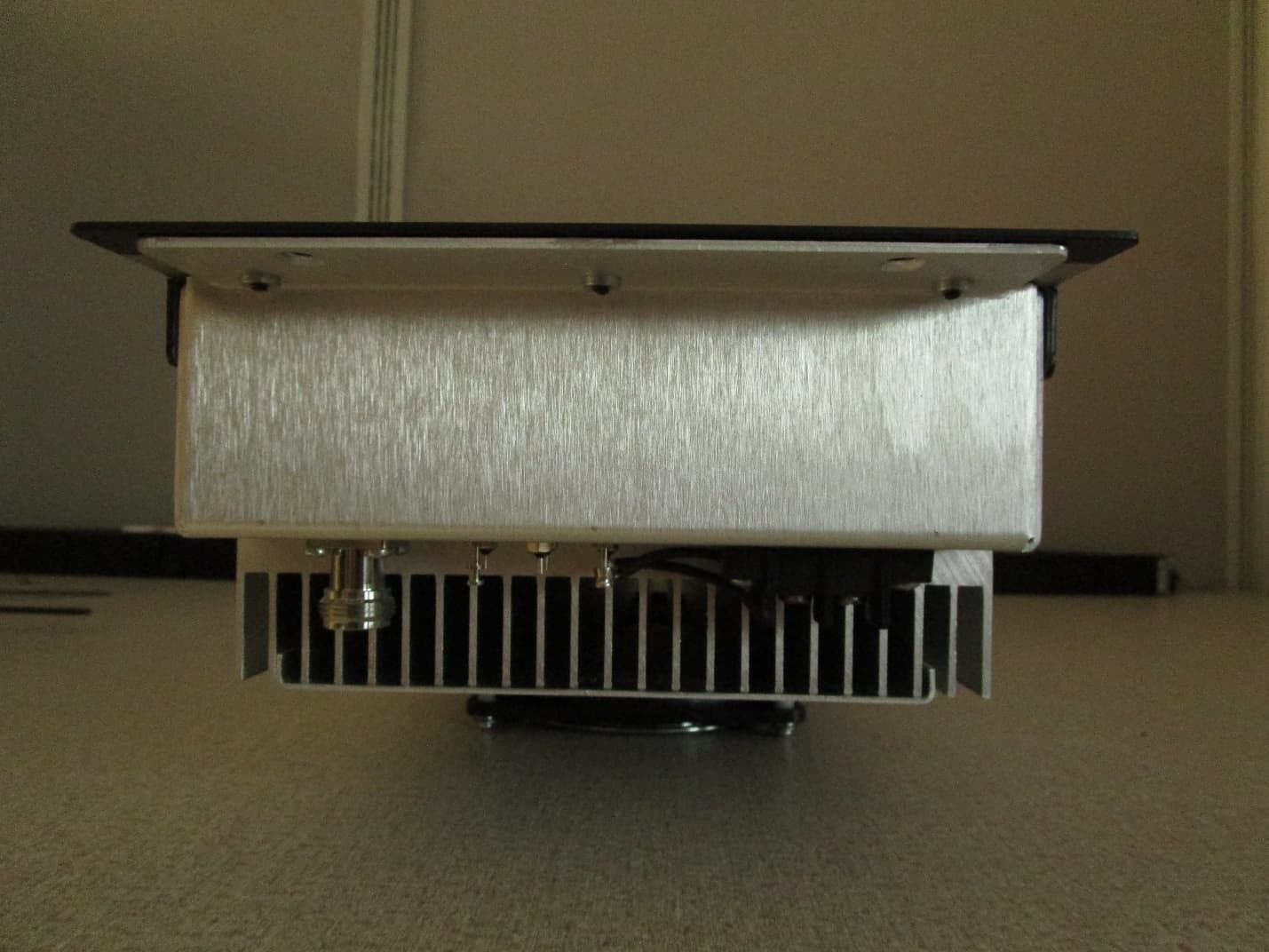
CWWP10XXDE1
Mar 10, 2020VHF AMPLIFIER
Equipment Class
B9B - Part 90 Class B Industrial Booster (non-SMR)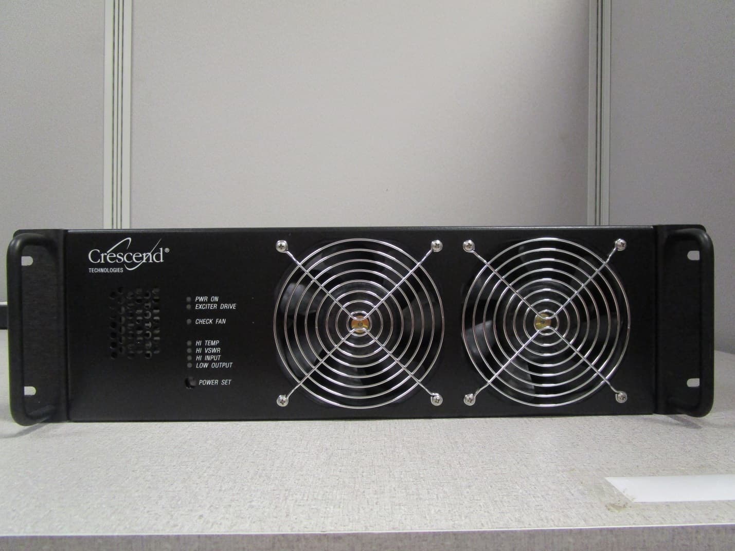
CWWP25XXHA3
Jan 27, 2020HIGH BAND HIGH POWER AMPLIFIER
Equipment Class
B9A - Part 90 Class A Industrial Booster (non-SMR)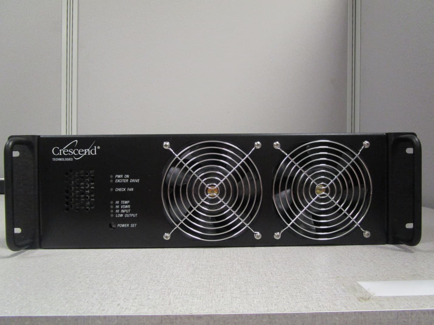
CWWP25XXGA3
Jan 21, 2020LOW BAND HIGH POWER AMPLIFIER
Equipment Class
B9A - Part 90 Class A Industrial Booster (non-SMR)
CWWP2RTK450
May 10, 201525Watt One-Way Amplifier
Equipment Class
AMP - Amplifier