CWWP310KL1C9UPAMPLIFIER
Crescend Technologies LLC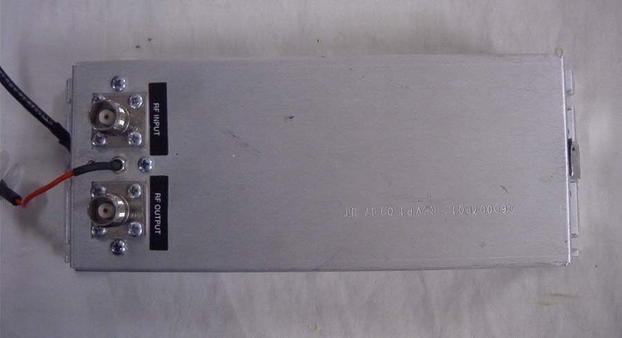
Click to zoom
Application Details
- Equipment Class
- AMP - Amplifier
- Date of Grant
- Jan 31, 2008
- Application Purpose
- Original Equipment
- Date of Application
- Jan 31, 2008
- Equipment Note
- AMPLIFIER
- Frequency Range
- 935.88750000 - 936.98750000
- Company
- Crescend Technologies LLC
- Country
- United States
Documents & Files
Document Text
Text extracted from the exhibit documents filed with the FCC. Open a document above to read the original.
Users Manual
Power Amplifier Users Manual 1. General Information. 1.1. The Power Amplifier (PA) is a C-class unit. It is intended for amplification of single carrier phase (frequency) modulated narrowband signals. 1.2. PA is intended to work with a radio, operated in simplex mode using a switching bypass relay. 1.3. The single amplifier covers both frequency ranges 896.8875-897.9875 MHz and 935.8875-936.9875 MHz. 1.4. Nominal output power is 30 W and nominal gain is 5 dB with 10 W input power. 1.5. Working input power range is 10 W - 15W. 1.6. Input VSWR is not greater than 2:1. 1.7. DC power supply voltage range is 13.0 – 13.6 V. 1.8. DC current consumption is not greater than 9 A. 1.9. The base plate temperature range is -30ºC to +70ºC. 1. Caution: Be very careful to not stress the 13.6 VDC red wire/filter interface near the two rf connectors. 2. The Power Amplifier (PA) should be screwed to a flat surface of massive metal construction that is able to serve as its heatsink. A good thermal contact between the lower base of PA chassis and heatsink must be provided (a thin layer of thermal grease is highly recommended). Take care that all dirt and dust has been removed before screwing the PA to the mounting surface. 3. The red DC wire should be connected to + 13.6 VDC line; black (return) DC wire should go to ground. The amplifier is protected against reverse voltage polarity (it shorts a circuit with the wrong polarity) but for time not greater than 0.3 sec. 3. The nominal DC power supply voltage should be 13.6 V. 4. RF input power shall be in limits 10 W – 15 W within the over the specified frequencies and should not exceed 2 W outside this range. 5. Output load VSWR shall not exceed 2:1. 6. It is recommended to keep the temperature of heatsink in the place of PA installation less then +70°C. The unit has an overheat protection that activates and blocks switching to transmit mode when the lower base temperature reaches +85°C. The unit returns to normal operation when the temperature drops to approximately +70°C. 7. The unit is designed for a transmit/receive duty cycle up to 1:4 with the transmitting duration not greater than 1 min.
Cover Letter(s)
920 E. State Parkway • Schaumburg, IL 60173 Toll Free Number: (800) USA MADE (800.872.6233) Phone: 847.908.5400 • Fax: 847.908.5408 www.crescendtech.com • E-mail: [email protected] January 9, 2008 Federal Communications Commission Authorization and Evaluation Division Confidentiality Request regarding application for certification of FCC ID: CWWP310KL1C9UP Pursuant to Sections 0.457 and 0.459 of the Commission’s Rules, we hereby request confidential treatment of information accompanying this application as outlined below: Schematic Schematic.pdf Block Diagram Block Diagram.pdf Parts List Power Amplifier Parts List.pdf Operational Description PA Description.pdf Tuning Procedure Tune up Procedure.pdf The above materials contain trade secrets and proprietary information not customarily released to the public. The public disclosure of these materials may be harmful to the applicant and provide unjustified benefits to its competitors. Pursuant to DA 04-1705 June 15, 2004 of the Commission’s public notice, we also request temporary confidential treatment of information accompanying this application as outlined below: External Photos ExternalPhotos.pdf Internal Photos InternalPhotos.pdf Test Set Up Photo 3501AUT7_Teststp.jpg User manual UserManual.pdf Sincerely, Mark Obermann
ID Label/Location Info
Crescend Technologies SN: xxxxxxxxx Model: P3-10KL1-C9-UP Pin: xx Pout: xx FCC ID: CWWP310KL1C9UP Freq: xx IC: 7291A - P310KL1C9UP Voltage: xx
Internal Photos
APPLICANT: CRESCEND TECHNOLOGIES, LLC. FCC ID: CWWP210KL1C9UP INTERNAL PHOTOS
RF Exposure Info
849 NW State Road 45 • P. O. Box 370 • Newberry, Florida 32669 USA Telephone (352) 472-5500 • (888) 472-2424 • FAX (352) 472-2030 • email: [email protected] JOB# 3501AUT7 January 31, 2008 FCC RF EXPOSURE EXHIBIT PART 1.1310 ENVIRONMENTAL ASSESSMENT FOR A UHF AMPLIFIER (90 S) 849 NW State Road 45 • P. O. Box 370 • Newberry, Florida 32669 USA Telephone (352) 472-5500 • (888) 472-2424 • FAX (352) 472-2030 • email: [email protected] TABLE OF CONTENTS 1. Test Report Information...........................................................................................1 2. Identification of the Equipment Under Test............................................................2 3. Standard test conditions...........................................................................................1 4. Part 1.1310 Environmental Assessment..................................................................1 5. Statement of compliance..........................................................................................1 849 NW State Road 45 • P. O. Box 370 • Newberry, Florida 32669 USA Telephone (352) 472-5500 • (888) 472-2424 • FAX (352) 472-2030 • email: [email protected] 1. TEST REPORT INFORMATION a) Laboratory: Timco Engineering, Inc 849 N.W. State Road 45 Newberry, Florida 32669 b) FCC Correspondence Reference Number: 7355 c) Client: Crescend Technologies, LLC 920 East State Parkway Schaumburg, IL 60173 d) Identification: FCC ID: CWWP310KL1CP9UP e) Description: VHF Amplifier f) EUT Condition: Not required unless specified in individual tests. g) Report Date: January 31, 2008 h) EUT Received: November 2, 2007 i) Sampling method: No sampling procedure used. j) Uncertainty: In accordance with Timco’s internal quality manual. k) Test results: The results presented in this report relate only to the item tested. l) Reproduction: This report must not be reproduced, except in full, without written permission from this laboratory. 849 NW State Road 45 • P. O. Box 370 • Newberry, Florida 32669 USA Telephone (352) 472-5500 • (888) 472-2424 • FAX (352) 472-2030 • email: [email protected] 2. IDENTIFICATION OF THE EQUIPMENT UNDER TEST NAME AND ADDRESS OF APPLICANT: Crescend Technologies, LLC 920 East State Parkway Schaumburg, IL 60173 MANUFACTURER: Applicant FCC ID: CWWP310KL1C9UP MODEL NO: P3-10KL1-C9-UP DESCRIPTION: VHF Amplifier TYPE OF EMISSION: Amplifier FREQUENCY RANGE, MHz: 935.8875 – 936.9875 MHz, 896.8875-897.9875 MHz POWER RATING, Watts: 35 Watts Switchable or Variable N/A MODULATION: Amplifier ANTENNA: 4 dBi omni directional vertical (typical antenna for this radio) With 15 feet of RG 8U. Attenuation at 900 MHz: Nominal Value: 1. dB/15 feet. typical installation NOTE: RF Power set to highest output across all probe readings/heights. 849 NW State Road 45 • P. O. Box 370 • Newberry, Florida 32669 USA Telephone (352) 472-5500 • (888) 472-2424 • FAX (352) 472-2030 • email: [email protected] 3. STANDARD TEST CONDITIONS Except as noted herein, the following conditions and procedures were observed during the testing: In accordance with ANSI C63.4-1992/2000, section 6.1.9, and unless otherwise indicated in the specific measurement results, the ambient temperature of the actual EUT was maintained within the range of 10 to 40 degrees C (50 to 104 degrees F) unless the particular equipment requirements specify testing over a different temperature range. Also, unless otherwise indicated, the humidity levels were in the range of 10% to 90% relative humidity. Prior to testing, the EUT was tuned up in accordance with the manufacturer's alignment procedures. All external gain controls were maintained at the position of maximum and/or optimum gain throughout the testing. Measurement results, unless otherwise noted, are worst-case measurements. Temperature: 89.5°F Humidity: 51% 4. PART 1.1310 ENVIRONMENTAL ASSESSMENT Specification: FCC: 47 CFR 1.1310 Measurement Guide: ANSI/IEEE C95.1 1992 Test Equipment: Maximum Permissible Exposure (MPE) measurement system, consisting of: Amplifier Research Model FM-5004 Amplifier Research, Isotropic Field Probe Model FP-5000 10 kHz – 1000 MHz Bird Wattmeter Model 43 with 850-960 MHz, 100 Watt slug 849 NW State Road 45 • P. O. Box 370 • Newberry, Florida 32669 USA Telephone (352) 472-5500 • (888) 472-2424 • FAX (352) 472-2030 • email: [email protected] Measurement Procedure: 1. The following measurements were performed with an Amplifier Research Field Probe using ANSI/IEEE C95.1 as a guide. 2. Prior to making any measurements, the measurements system was calibrated in accordance with the manufacturer’s procedures. 3. The EUT’s radiating element (antenna) was placed on a wooden table 80 cm high. The vertical whip antenna was mounted in a typical operational manner. 4. The remaining equipment necessary to operate the EUT was maintained at a distance from the measurement arrangement suitable to minimize interference with the measurements. 5. The minimum safe distance was calculated from the formula Power Density = EIRP /4חR² (Peak Watts/m²). The calculation is shown with the measurement data. 6. With the EUT operating at maximum power, a search was initiated for worst case emissions with the probe raised and lowered over a range 0 o 140 cm height range. plane of 0 to 360 degrees. Worst case emissions were found to be at point perpendicular from the antenna base and were the same at different axes. 7. Bird Wattmeter/Antenna measurements: 35 Watts conducted into a 50 Ohm Results follow: FCC Rules: 1.1307, 1.1310, 2.1091 Description, EUT: UHF Amplifier (90 S) Test Frequency, MHz = 930 Antenna Gain = 4 dBi Coax loss 1 dB Rated Probe: Amplifier Research FM-5004 Probe 849 NW State Road 45 • P. O. Box 370 • Newberry, Florida 32669 USA Telephone (352) 472-5500 • (888) 472-2424 • FAX (352) 472-2030 • email: [email protected] LIMITS: Uncontrolled Exposure 47 CFR 1.1310 0.3-1.234 MHz: Limit [mW/cm²] = 100 1.34-30 MHz: Limit [mW/cm²] = (180/f²) 30-300 MHz: Limit [mW/cm²] = 0.2 300-1500 MHz…
Text truncated - open the document above for the full version.
Test Report
849 NW STATE ROAD 45 NEWBERRY, FL 32669 USA PH: 888.472.2424 OR 352.472.5500 FAX: 352.472.2030 EMAIL: [email protected] HTTP://WWW.TIMCOENGR.COM FCC PT 90 AMPLIFIER TEST REPORT APPLICANT CRESCEND TECHNOLOGIES, LLC ADDRESS 920 EAST STATE PARKWAY SCHAUMBURG IL 60173 USA FCC ID CWWP310KL1C9UP IC LABEL 7291A-P310KL1C9UP MODEL NUMBER P3-10KL1-C9-UP PRODUCT DESCRIPTION VHF Amplifier DATE SAMPLE RECEIVED November 2, 2007 DATE TESTED November 27, 2007 TESTED BY Nam Nguyen APPROVED BY Mario de Aranzeta TIMCO REPORT NO. 3051AUT7TestReport.PDF TEST RESULTS PASS FAIL THE ATTACHED REPORT SHALL NOT BE REPRODUCED EXCEPT IN FULL WITHOUT THE WRITTEN APPROVAL OF TIMCO ENGINEERING, INC. Certificate # 0955-01 TABLE OF CONTENTS ATTESTATION STATEMENT............................................................................ 3 REPORT SUMMARY........................................................................................ 4 TEST ENVIRONMENT AND TEST SETUP......................................................... 4 DUT DESCRIPTION......................................................................................... 5 TEST EQUIPMENT.......................................................................................... 6 TEST PROCEDURES....................................................................................... 7 TEST RESULTS............................................................................................... 9 RF POWER OUTPUT............................................................................................................. 9 OCCUPIED BANDWIDTH.................................................................................................... 10 SPURIOUS EMISSIONS AT ANTENNA TERMINALS (CONDUCTED)..................................... 13 FIELD STRENGTH OF SPURIOUS EMISSIONS (RADIATED)................................................ 14 POWER LINE CONDUCTED INTERFERENCE..................................................................... 15 Applicant: Crescend Technolgoies LLC FCC ID: CWWP310KL1C9UP IC: 7291A-P310KL1C9UP MODEL #: P3-10KL1-C9-UP Report: W:\C\CRESCEND_CWW\3501AUT7\3501AUT7TestReport Page 2 of 15 ATTESTATION STATEMENT This equipment has been tested in accordance with the standards identified in the referenced test report. To the best of my knowledge and belief, these tests were performed using the measurement procedures described in this report. Test Certificate #0955-01 All instrumentation and accessories used to test products for compliance to the indicated standards are calibrated regularly in accordance with ISO 17025 requirements. I attest that the necessary measurements were made by me or under my supervision, at Timco Engineering, Inc. located at 849 N.W. State Road 45, Newberry, Florida 32669 USA. Authorized by: Mario de Aranzeta Signature: Mario de Aranzeta Function: Test Lab Supervisor / Engineer Date: December 10, 2007 Applicant: Crescend Technolgoies LLC FCC ID: CWWP310KL1C9UP IC: 7291A-P310KL1C9UP MODEL #: P3-10KL1-C9-UP Report: W:\C\CRESCEND_CWW\3501AUT7\3501AUT7TestReport Page 3 of 15 REPORT SUMMARY Disclaimer The test results relate only to the items tested. Purpose of Test To show the DUT in compliance with FCC CFR 47, Part 90 and IC RSS-131 requirements for amplifiers Test Procedures ANSI/TIA 603-C: 2004 FCC CFR 47 Part 90 IC RSS-131 ANSI C63.4: 2003 Related Approval N/A TEST ENVIRONMENT AND TEST SETUP Test Facility All tests were conducted by Timco Engineering Inc. located at 849 NW State Road 45, Newberry, FL 32669 USA Laboratory Test Condition Temperature: 26ºC Relative humidity: 50%. Deviation from the standards No deviation Modification to the DUT No modification was made. Test Exercise (software etc.) The DUT was placed in continuous transmitting mode of operation. System Setup Stand alone device. Applicant: Crescend Technolgoies LLC FCC ID: CWWP310KL1C9UP IC: 7291A-P310KL1C9UP MODEL #: P3-10KL1-C9-UP Report: W:\C\CRESCEND_CWW\3501AUT7\3501AUT7TestReport Page 4 of 15 DUT DESCRIPTION Manufactured by Crescend Technologies, LLC Product Description Amplifier FCC ID CWWP310KL1C9UP IC Label IC: 7291A-P310KL1C9UP M/N P3-10KL1-C9-UP Family M/Ns N/A S/N N/A Operating Freq (935.8875 – 936.9875) MHz (896.8875 – 897.9875) MHz Max. Output Pwr 35W Modulation N/A Amplifier Power Source 13.0 VDC DC Power Test Item Preproduction Type of DUT Fixed/Mobile Amplifier Applicant: Crescend Technolgoies LLC FCC ID: CWWP310KL1C9UP IC: 7291A-P310KL1C9UP MODEL #: P3-10KL1-C9-UP Report: W:\C\CRESCEND_CWW\3501AUT7\3501AUT7TestReport Page 5 of 15 TEST EQUIPMENT Device Manufacturer Model Serial Number Cal/Char Date Due Date Analyzer Tan Tower Spectrum Analyzer HP 8566B Opt 462 3138A07786 3144A20661 CAL 12/7/05 12/7/07 Analyzer Tan Tower RF Preselector HP 85685A 3221A01400 CAL 12/7/05 12/7/07 Analyzer Tan Tower Quasi-Peak Adapter HP 85650A 3303A01690 CAL 12/8/05 12/8/07 Analyzer Tan Tower Preamplifier HP 8449B-H02 3008A00372 CAL 12/8/05 12/8/07 Antenna: Biconnical Electro- Metrics BIA-25 1171 CAL 4/29/07 4/29/09 Antenna: Log-Periodic Electro- Metrics LPA-25 1122 CAL 12/1/06 12/1/08 Antenna: Double- Ridged Horn Electro- Metrics RGA-180 2319 CAL 12/29/06 12/29/08 LISN Electro- Metrics ANS-25/2 2604 CAL 10/5/06 10/5/08 Termaline Wattmeter Bird Electronic Corporation 611 16405 CAL 3/15/07 3/15/09 Applicant: Crescend Technolgoies LLC FCC ID: CWWP310KL1C9UP IC: 7291A-P310KL1C9UP MODEL #: P3-10KL1-C9-UP Report: W:\C\CRESCEND_CWW\3501AUT7\3501AUT7TestReport Page 6 of 15 TEST PROCEDURES Power Line Conducted Interference The procedure used was ANSI 63.4-2003 using a 50uH LISN. Both lines were observed with the DUT transmitting. The bandwidth of the spectrum analyzer was 10 kHz with an appropriate sweep speed. RF Power Output The RF power output was measured at the antenna feed point using a peak power meter. A 50-ohm, resistive wattmeter was connected to the RF output connector. With a nominal battery voltage, and the transmitter properly adjusted the RF output measures: Applica…
Text truncated - open the document above for the full version.
Contact Information
Applicant
James Hougo(President)
Test Firm
Timco Engineering, Inc.Sid Sanders
Technical Specifications
| # | Rule Parts | Frequency Range | Power Output | Emission | Tolerance |
|---|---|---|---|---|---|
| 2 | 9 | 935.8875 MHz - 936.9875 MHz | 35 W | G7W | Amp |
Other Applications from Crescend Technologies LLC
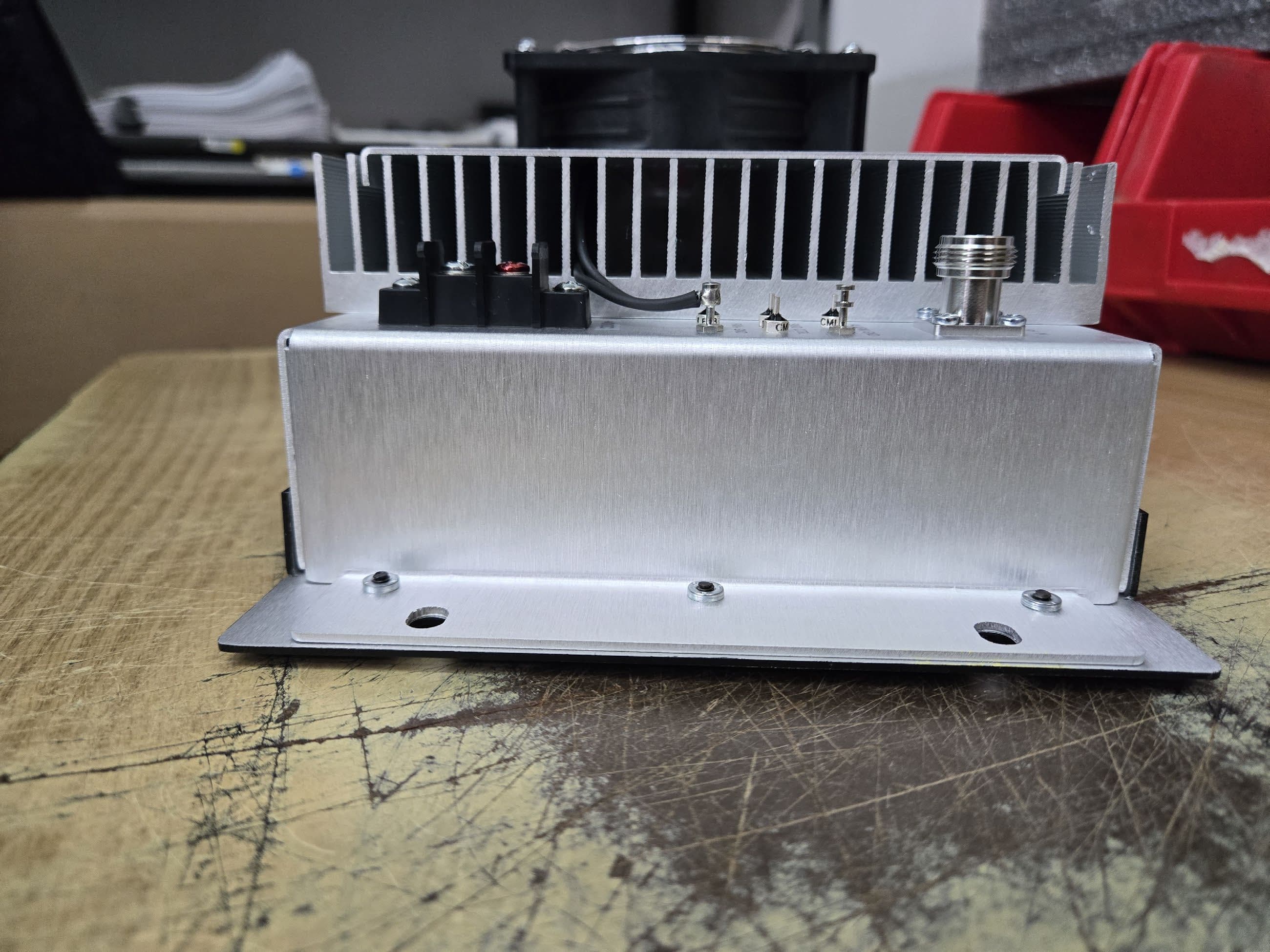
CWWP25XXDE4
Sep 17, 2025Power Amplifier AB to C Class
Equipment Class
B2I - Part 20 Industrial Booster (CMRS)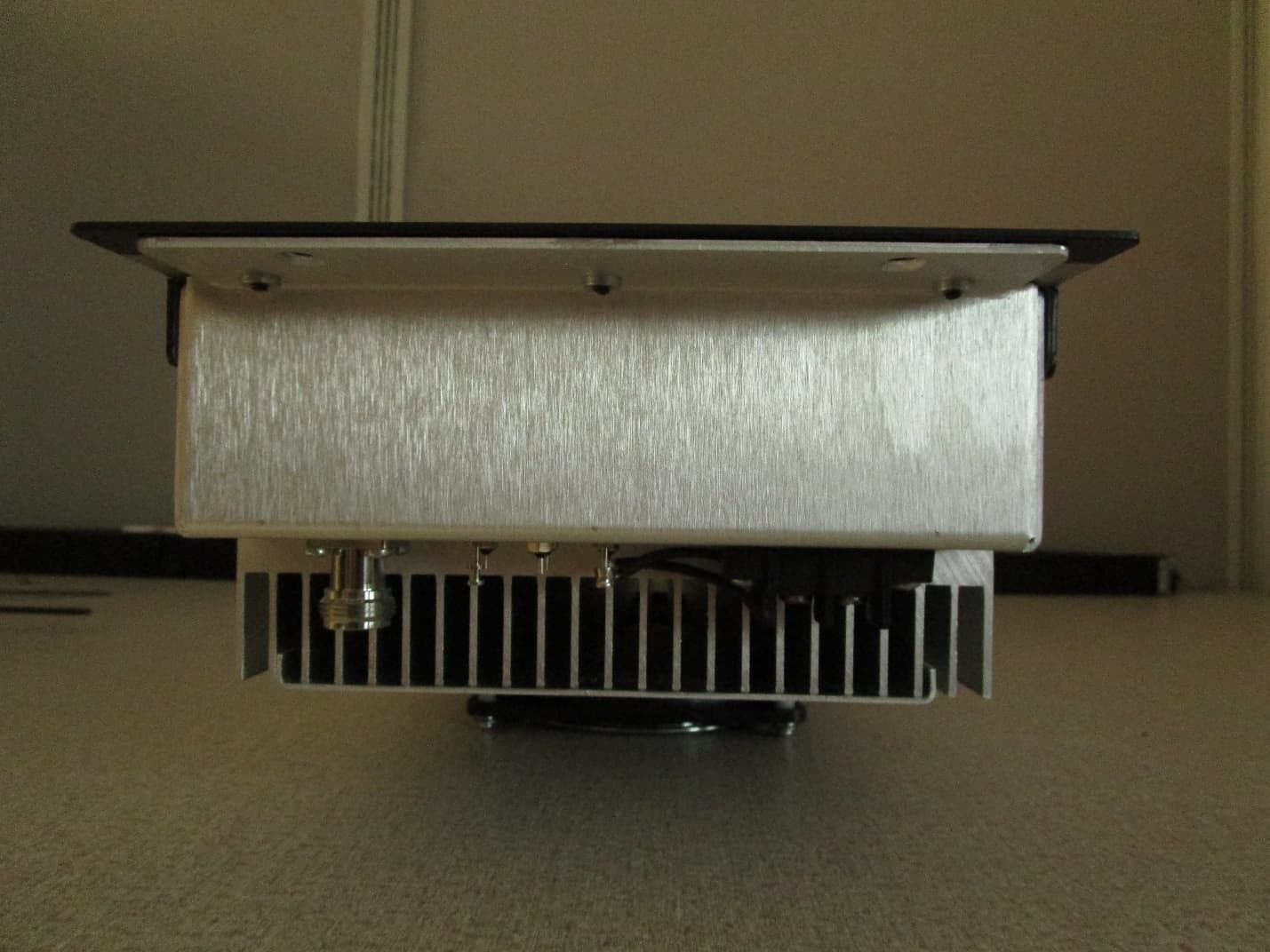
CWWP10XXDE1
Mar 10, 2020VHF AMPLIFIER
Equipment Class
B9B - Part 90 Class B Industrial Booster (non-SMR)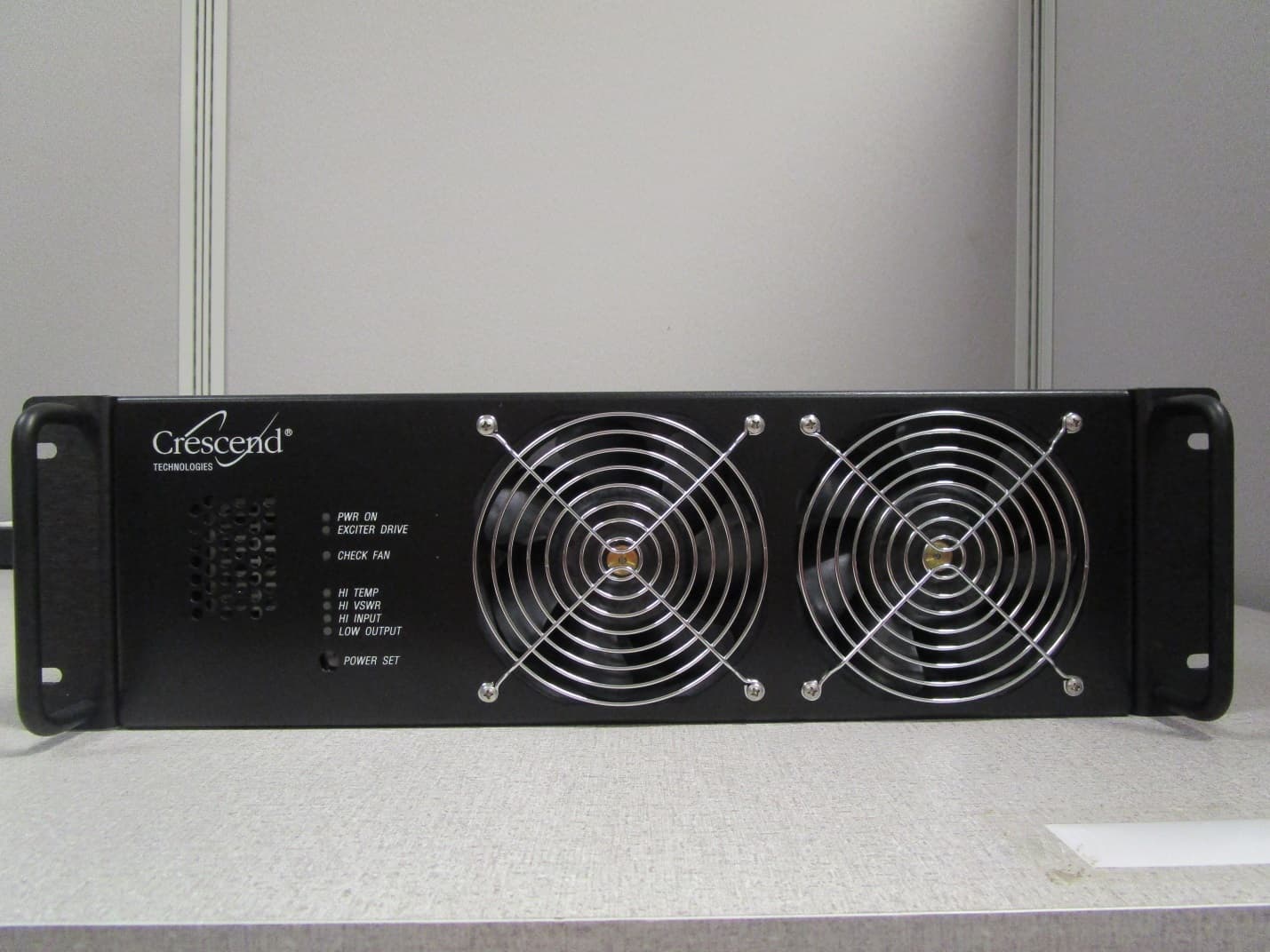
CWWP25XXHA3
Jan 27, 2020HIGH BAND HIGH POWER AMPLIFIER
Equipment Class
B9A - Part 90 Class A Industrial Booster (non-SMR)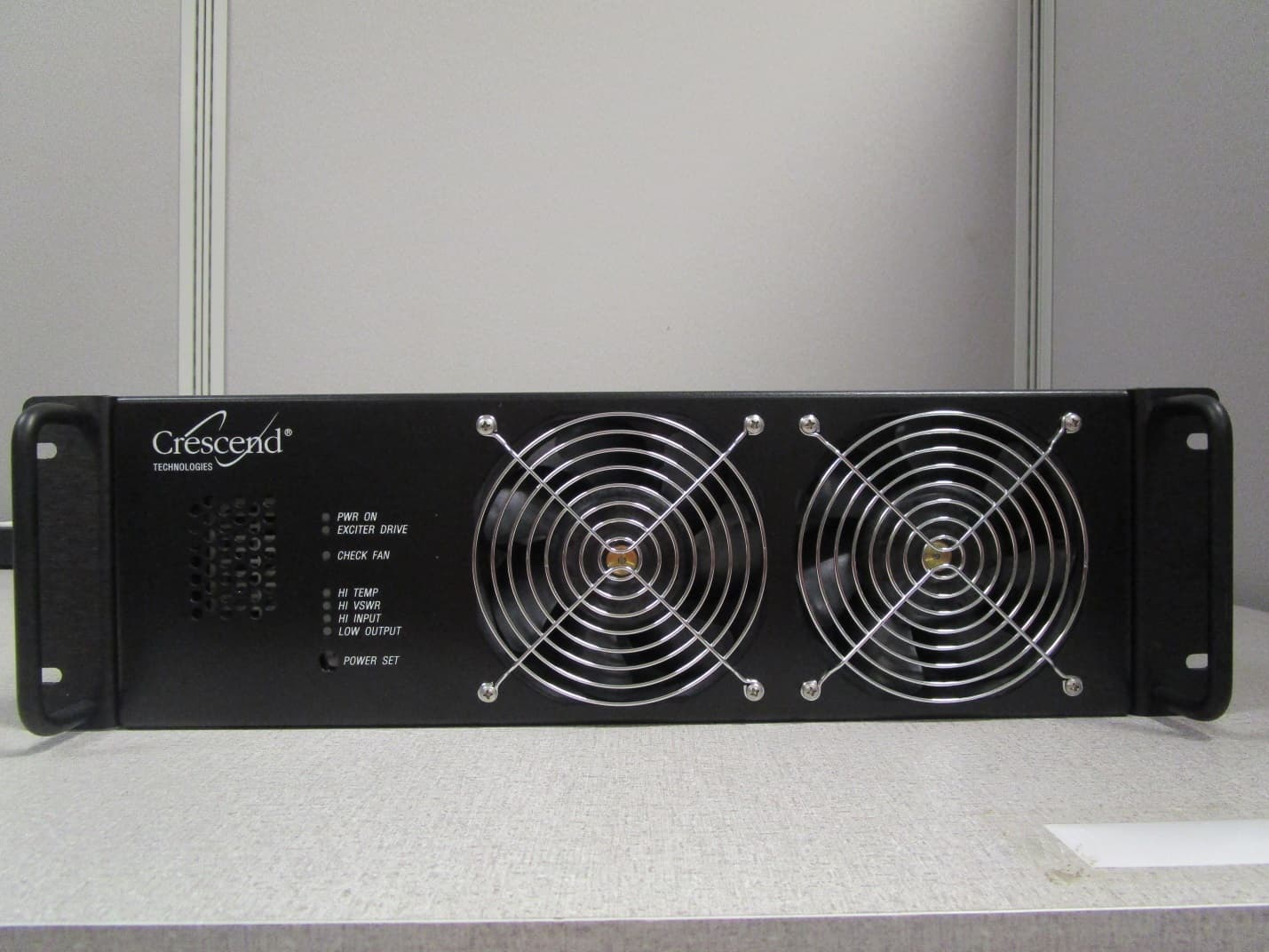
CWWP25XXGA3
Jan 21, 2020LOW BAND HIGH POWER AMPLIFIER
Equipment Class
B9A - Part 90 Class A Industrial Booster (non-SMR)
CWWP2RTK450
May 10, 201525Watt One-Way Amplifier
Equipment Class
AMP - Amplifier