CWWVB0001Continuous Duty Power Amplifier
Crescend Technologies LLC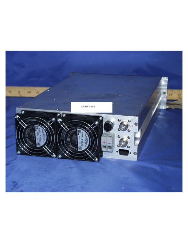
Click to zoom
Application Details
- Equipment Class
- AMP - Amplifier
- Date of Grant
- Oct 05, 2000
- Application Purpose
- Original Equipment
- Date of Application
- May 16, 2000
- Equipment Note
- Continuous Duty Power Amplifier
- Frequency Range
- 450.00000000 - 470.00000000
- Company
- Crescend Technologies LLC
- Country
- United States
Documents & Files
Document Text
Text extracted from the exhibit documents filed with the FCC. Open a document above to read the original.
Users Manual
INSTALLATION & SERVICE MANUAL MODEL H100 CONTINUOUS DUTY POWER AMPLIFIER 450-470 MHz May 17, 2000 Crescend Technologies 2255 Lois Drive, Suite 1 Rolling Meadows, IL 60008 Tel: 847 593 1213 Fax: 847 593 1320 Web Site: www.crescendtech.com Rev 1. 2 Par. TABLE OF CONTENTS Section 1 Page No. General Description No. 1-1 Introduction 4 1-2 General Description 4 1-3 Functional and Physical Specifications 4 1-4 Equipment Changes 4 1-5 Ordering Information 4 Section 2 Installation 2-1 Introduction 6 2-2 Electrical Service Recommendations 6 2-3 Unpacking and Inspection 6 2-4 Installation Instructions 6 2-5 Amplifier Module Alarm and Control Connector 7 Section 3 Operating Instructions 3-1 Introduction 8 3-2 Location and Function of Amplifier Module Control and Indicators 8 3-3 Initial Start-Up and Operating Procedures 8 3-4 Variable Input Switch 9 Section 4 Principles of Operation 4-1 Introduction 10 4-2 RF Input Signal 10 4-3 RF Output Load 10 4-4 Functional Description 10 4-5 H100 Amplifier Module 10 4-5.1 Main Amplifier 10 4-5.2 Loop Control 11 4-5.3 Amplifier Monitoring 11 4-5.4 Amplifier Module Cooling 11 4-6 Power Distribution 11 Rev 1. 3 TABLE OF CONTENTS (Continued) Section 5 Maintenance 5-1 Introduction 12 5-2 Periodic Maintenance 12 5-3 Test Equipment Required for Test 12 5-4 Cleaning air Inlets/Outlets 13 5-5 Performance Test 13 5-5.1 Amplifier Performance Test 13 5-6 Field Replaceable Parts and Modules 14 5-6.1 H100 Power Amplifier Module 14 5-6.2 Cooling Fans 14 5-6.3 Fuse 15 Section 6 Troubleshooting 6-1 Introduction 16 6-2 Troubleshooting 16 6-3 Return for Service Procedure 16 6-3.1 Obtaining an RMA 16 6-3.2 Repackaging for Shipment 16 Figure LIST OF ILLUSTRATIONS Page 4-1 Variable Input Switch 10 4-2 H100 Block Diagram 11 5-1 Amplifier Test Setup diagram 15 LIST OF TABLES Table Page 1-1 Major Amplifier Components 4 1-2 H100 Amplifier Functional Specifications 5 1-3 Load Mismatch Tolerance 5 2-1 Amplifier Module Alarm and Control Connections 7 3-1 H100 Amplifier Module Control and Indicators 8 5-1 Periodic Maintenance 12 5-2 Test Equipment Required 12 6-1 Troubleshooting 16 Rev 1. 4 1. GENERAL DESCRIPTION 1.1. INTRODUCTION This manual contains information and procedures for installation, operation, of Crescend’s H100 Continuous Duty Power Amplifier. The manual is organized into five sections as follows: Section 1. General Description Section 2. Installation Section 3. Operating Instructions Section 4. Principles of Operation Section 5. Maintenance Section 6: Troubleshooting 1.2. GENERAL DESCRIPTION The H100amplifier is designed for trunking and conventional repeater applications requiring high duty cycles. The H100 amplifier operates from RF power sources of 250 milliwatts up to 25 watts. The amplifier consists of an input attenuator, a predriver amplifier, a microprocessor circuit control, and two stages of amplification followed by a 7-pole distributed low-pass filter and associated control circuitry. The H100 amplifier has a microprocessor control board that maintains a constant output power under varying signal input and output load conditions. A system functional block diagram of the Model H100 amplifier is contained in section 4 of this manual. 1.3. FUNCTIONAL AND PHYSICAL SPECIFICATIONS Functional and physical specifications for the H100 amplifier are listed in tables 1-2 and 1-3. 1.4. EQUIPMENT CHANGES Crescend Technologies, Inc. reserves the right to make minor changes without notice, including but not necessarily limited to component substitution and circuitry changes. Such changes may or may not be incorporated in this manual, although it is our intention to keep each manual as up-to-date as possible. To that end, we ask that you, our customer, share with us information acquired in field situations which might be of assistance to another user. If you share it with us, we’ll pass it around. 1.5. ORDERING INFORMATION Table 1-1 following gives the part numbers and descriptions to be used when ordering either an entire amplifier or replacement fans. Table 1-1. Major Amplifier Components MODEL NUMBER DESCRIPTION H100 250 mW – 25 W 450-470 MHz Amplifier 800-00889-001 Fan Assembly Rev 1. 5 Table 1-2. H100 Amplifier Functional Specifications Frequency Range: 450-470 MHz. Operating Voltage: +28 Vdc (±1.0 Vdc) Current Draw 9 Amperes Typical; 11 Amperes Maximum Duty Cycle: 100% Power Input: 250 mW - 25 W. Power Output: 100 Watts Spurious & Harmonics. -70 dBc (Minimum) Input/Output Impedance 50 ohms (Nominal) Load VSWR Tolerance See Chart Input/Output Connector: Type N Female Vertical Mounting: 10.47” Horizontal Mounting: 3.38’ Depth. 17.0” Weight: 20 Pounds Nominal Cooling Method: Fan Forced Air Over Heatsink Operating Temp. Range: 0 °C. to +60 °C. Storage & Transport: -10 °C. to +70 °C. Humidity: 80% at +40 “C. (Non condensing) Altitude: 10,000 Feet Maximum OPTIONS Remote Control/Display Panel INDICATORS DC PWR ON, LOW OUTPUT, LOW INPUT, HIGH INPUT, HIGH VSWR, OVER TEMP., L.E.D. POWER BAR METER CONTROLS PWR CONTROL (-10 dB) NOTES: Manufacturer’s Rated Output Power of this Equipment is for Single Carrier Operation. All specifications apply at +28 Vdc operating voltage. Table 1-3. Load Mismatch Tolerance Full Power, Sustained Operation 2:1 Maximum Sustained Operation at Reduced Power 3:1 Microprocessor Shutdown 10:1 Rev 1. 6 2. INSTALLATION 2.1. INTRODUCTION This section contains installation recommendations, unpacking, inspection, and installation instructions for the H100 amplifier. Carefully read all material in this section prior to equipment unpacking or installation. Also read and review the operating procedures in Section 3 prior to installing the equipment. It is important that the licensee perform these tasks correctly and in good faith. If applicable, carefully read Parts 73 and 74 of the Federal Communications Commission (FCC) rules to determine how they apply to your installation. DON’T TAKE CHANCES WITH YOUR LICENSE. 2.2. ELECTRICAL SERVICE RECOMMENDATIONS Crescend Techn…
Text truncated - open the document above for the full version.
ID Label/Location Info
PROPOSED FCC ID LABEL FORMAT Applicant: Crescend Technologies, LLC 2255 Lois Drive, Suite 1, Rolling Meadows, IL 60008 Model: H-100 FCC ID: CWWVB0001 FCC ID: CWWVB0001 This device complies with part 15 of the FCC Rules. Operation is subject to the following two conditions: (1) This device may not cause harmful interference, and (2) this device must accept any interference received, including interference that may cause undesired operation. FCC ID LABEL AREA
Internal Photos
Interior Pictures of H100 Single Channel Amplifier Overview of Interior Amplifier Control PCB Driver PCB Final Transistor Module pallets Filter and Combiner PCB Final Transistors (MRF184) in pallet construction. Filter and Combiner PCB Driver PCB Combiner filter PCB Fan Control PCB Control PCBs
Internal Photos
PROPOSED FCC ID LABEL FORMAT Applicant: Crescend Technologies, LLC 2255 Lois Drive, Suite 1, Rolling Meadows, IL 60008 Model: H-100 FCC ID: CWWVB0001 FCC ID: CWWVB0001 This device complies with part 15 of the FCC Rules. Operation is subject to the following two conditions: (1) This device may not cause harmful interference, and (2) this device must accept any interference received, including interference that may cause undesired operation. FCC ID LABEL AREA Interior Pictures of H100 Single Channel Amplifier Overview of Interior Amplifier Control PCB Driver PCB Final Transistor Module pallets Filter and Combiner PCB Final Transistors (MRF184) in pallet construction. Filter and Combiner PCB Driver PCB Combiner filter PCB Fan Control PCB Control PCBs
Operational Description
DESCRIPTION OF PRODUCT: The H100 amplifier is designed for trunking and conventional repeater applications requiring high duty cycle. The H100 amplifier operates from RF power sources of 250 milliwatts up to 25 watts. The amplifier consists of an input attenuator, a predriver amplifier, a microprocessor control circuit, and two stages of amplification followed by a 7-pole distributed low-pass filter and associated control circuitry. The H100 amplifier has a microprocessor control board that maintains a constant output power under varying signal input and output load conditions. A system functional block diagram of the Model H100 amplifier is contained in section 4 of this manual. The H100 amplifier (see block diagram figure 4-2 in manual) is a linear, single channel amplifier that operates in the frequency band from 450 MHz to 470 MHz. The amplifier specifications are listed in the table 1-2 of operating manual. Each amplifier is a self-contained plug-in module and is functionally independent of other amplifier modules. The amplifier modules are designed for parallel operation to achieve high peak power output, and for redundancy in unmanned remote locations. Each amplifier in the system can simultaneously transmit carrier frequencies, a total power output of 100 Watts per amplifier.
Test Report
Note: The web server has been shut down for a couple of days. I can be reached at our new email address at: [email protected]. NOTE: The following letter was sent to the FCC under separate cover. I have attached it to the exhibits to reduce any confusion on company name. Note: I sent schematics and label information but did not receive the OK status report back. Please let me know if you did not receive these. May 17, 2000 FCC, Laboratory Division Equipment Authorization Branch 7435 Oakland Mills Road Columbia, Md. 21046 To Whom It May Concern: Effective immediately, Vocom Products Company, L.L.C. (Grantee Code CWW) has changed its name to: Crescend Technologies, L.L.C. The ownership and address have not changed. Also effective immediately, Crescend Technologies has acquired the amplifiers listed on Schedule 1.1 from Powerwave Technologies. Please convert these to Crescend’s grantee code CWW. Please call or email me any questions. Thank you. Sincerely, James Hougo President [email protected]
Test Report
TABLE OF CONTENTS FIG 1 Occupied bandwidth 460 MHz output of amplifier FIG 2 Occupied bandwidth 460 MHz output signal generator FIG 3 Occupied bandwidth 470 output of amplifier FIG 4 Occupied bandwidth 470 MHz output from signal generator FIG 5 Spurious Emissions @ Antenna 460 MHz 30MHz-1GHz FIG 6 Spurious Emissions @ Antenna 460 MHz 1GHz-2GHz FIG 7 Spurious Emissions @ Antenna 460 MHz 2GHz-5GHz FIG 8 Spurious Emissions @ Antenna 470 MHz 30MHz-1GHz FIG 9 Spurious Emissions @ Antenna 470 MHz 1GHz-2GHz FIG 10 Spurious Emissions @ Antenna 470 MHz 2GHz-5GHz FIG 11 460 MHz field strength radiation horizon 400mhz-5800mhz FIG 12 460 MHz field strength radiation vertical 400-5800 MHz FIG 13 470 MHz field strength radiation horizon 400-5800 MHz FIG 14 470 MHz field strength radiation vertical 400-5800 MHz
Test Report
FCC CFR47 PART 90 CERTIFICATION TEST REPORT FOR SINGLE CHANNEL 100 WATT AMPLIFIERS MODEL: H100 FCC ID: CWWVB0001 ISSUE DATE: MAY 16, 2000 CRESCEND TECHNOLOGIES, L.L.C. 2255 LOIS DRIVE, SUITE 1 ROLLING MEADOWS, IL 60008 2 TABLE OF CONTENTS PAGE 1. FCC CERTIFICATION INFORMATION (Section 2.1033) 3 2. VERIFICATION OF COMPLIANCE 5 3. TEST FACILITY 6 4. MEASUREMENT INSTRUMENTATION 6 5. MEASURING INSTRUMENT CALIBRATION 6 6. UNITS OF MEASUREMENT 6 7. RADIATED EMISSION TEST PROCEDURE 6 8. AMBIENT CONDITIONS 7 9. EQUIPMENT MODIFICATIONS 7 10. TEST EQUIPMENT LIST 7 11. CONFIGURATION BLOCK DIAGRAM 8 SECTION 2.1046 RF POWER OUTPUT 9 SECTION 2.1047 MODULATION CHARACTERISTICS 10 SECTION 2.1049 OCCUPIED BANDWIDTH 10 SECTION 2.1051 SPURIOUS EMISSION AT ANTENNA TERMINALS 11 SECTION 2.1053 FIELD STRENGTH OF SPURIOUS RADIATION 12 SECTION 2.1055 FREQUENCY STABILITY 13 ATTACHMENTS 1. EUT PHOTOGRAPHS 2. INSTALLATION & SERVICE MANUAL 3. SCHEMATICS 4. PROPOSED FCC ID LABEL FORMAT 3 1) FCC CERTIFICATION INFORMATION The following information is in accordance with FCC Rules, 47CFR Part2, Sections 2.1033 –2.1057. Section 2.1033 1. Applicant/Manufacturer: CRESCEND TECHNOLOGIES, LLC 2255 LOIS DRIVE, SUITE 1 ROLLING MEADOWS, IL 60008 Contact person: JIM HOUGO Telephone number: 847 593 1213 2. FCC ID: CWWVB0001, Model: H-100 3. Instructions/Installation Manual: Refer to Attachment: Installation and Service manual. 4. Type of Emissions: F3E 5. Frequency Range: Power Amplifier: 450-470 MHz 6. Maximum Power Rating: 100 Watts 7. Maximum power rating as defined in Section 90.635(b): < 500Watts. 8. Applied voltage: 22-29 VDC Current: 9 Amps typical, 11 Amps Maximum Refer to Attachment: Specifications included in Installation and Service manual. 9. Tune-up Procedure: No tuning is required if properly assembled. 10. Function of Each Active Device: ITEM VENDOR VENDOR PART NO. QTY PART NAME 1 MINI CKTS ERA 3SM 1 MIC AMP. 2 RFMD RF2114 1 MIC AMP 3 MOTOROLA MRF184 2 TRANSISTOR 4 MOTOROLA MRF182 1 TRANSISTOR Schematics are attached in a PDF file. Confidentiality is requested for these items. 4 Means for Frequency Stabilization: Not Applicable. Eut is a power amplifier Means for Limiting Modulation: Not Applicable. Eut is a power amplifier Means for Limiting Power: Not Applicable. Means for Attenuating Higher Audio Frequencies: 7-pole low-pass filters at the output to suppress spurious emission. 11. FCC ID label format: A drawing of the equipment identification nameplate appears under Attachment: PROPOSED FCC ID LABEL FORMAT. 12. Photograph: Photographs of the equipment, internal and external views, are found in the Attachment: Eut Photographs. 13. Description of Digital Modulation Techniques: Not Applicable. Standard Test Condition The power amplifier was tested under the following conditions: AC Supply Voltage: 120Vac, 60Hz DC Supply Voltage: 28Vdc The amplifier was aligned and tuned up according to manufacturer’s alignment procedure, prior to testing. All data presented represents the worst-case parameter being measured. Normal operation is from 25 - 29 Vdc sources. 5 2) VERIFICATION OF COMPLIANCE DESCRIPTION OF PRODUCT: The H100 amplifier is designed for trunking and conventional repeater applications requiring high duty cycle. The H100 amplifier operates from RF power sources of 250 milliwatts up to 25 watts. The amplifier consists of an input attenuator, a predriver amplifier, a microprocessor control circuit, and two stages of amplification followed by a 7-pole distributed low-pass filter and associated control circuitry. The H100 amplifier has a microprocessor control board that maintains a constant output power under varying signal input and output load conditions. A system functional block diagram of the Model H100 amplifier is contained in section 4 of this manual. The H100 amplifier (see block diagram figure 4-2 in manual) is a linear, single channel amplifier that operates in the frequency band from 450 MHz to 470 MHz. The amplifier specifications are listed in the table 1-2 of manual. Each amplifier is a self-contained plug-in module and is functionally independent of other amplifier modules. The amplifier modules are designed for parallel operation to achieve high peak power output, and for redundancy in unmanned remote locations. Each amplifier in the system can simultaneously transmit carrier frequencies, a total power output of 100 Watts per amplifier. TYPE OF EQUIPMENT SINGLE CHANNEL 100W AMPLIFIER MEASUREMENT DISTANCE: 3 METER TECHNICAL LIMIT: FCC 90.210, 90.691 FCC RULES: PART 2, PART 15, PART 90 EQUIPMENT AUTHORIZATION PROCEDURE TYPE ACCEPTANCE MODIFICATIONS MADE ON EUT NO 6 3) TEST FACILITY The open test sites and conducted measurement facilities used to collect the radiated emissions data are located at DSL Electronic Systems, INC., 166 South Cater, Genoa City, WI 53128. Crescend preformed the RF Output Power, Occupied Bandwidth and Conducted Emissions testing at our facility at 2255 Lois Drive, Rolling Meadows, Il 60008. 4) MEASUREMENT INSTRUMENTATION Radiated emissions were measured with one or more of the following types of linearly polarized antennas: tuned dipole, biconical, log periodic, BI-log, ridged waveguide, and liner horn. EMI receivers were used for line conducted readings; spectrum analyzers with pre-selectors and quasi-peak detectors were used to perform radiated measurements. Receiving equipment (i.e., receiver, analyzer, quasi-peak adapter, pre-selector) and LISNs conform to CISPR specification for “Radio Interference Measuring Apparatus and Measurement Methods,” Publication 16. Calibrated wideband preamplifiers, coaxial cables, and coaxial attenuators are also used for making measurements. 5) MEASURING INSTRUMENT CALIBRATION The measuring equipment, which was utilized in performing the tests documented herein, has been calibrated in accordance with the manufacturer's recommendations for utilizing calibration equipment, which is traceable to recognized national standards. 6) UNITS OF MEASUREME…
Text truncated - open the document above for the full version.
Test Setup Photos
Bench Set up for H100 Amplifier
Contact Information
Applicant
James Hougo(President)
Technical Contact
VOCOMMark Obermann
[email protected]8475931213
2255 LOIS DR · ROLLING MEADOWS, Louisiana · United States
Non-Technical Contact
VOCOMJAMES HOUGO
[email protected]8475931213
Technical Specifications
| # | Rule Parts | Frequency Range | Power Output | Emission |
|---|---|---|---|---|
| 1 | 90 | 450 MHz - 470 MHz | 100 W | F3E |
Other Applications from Crescend Technologies LLC
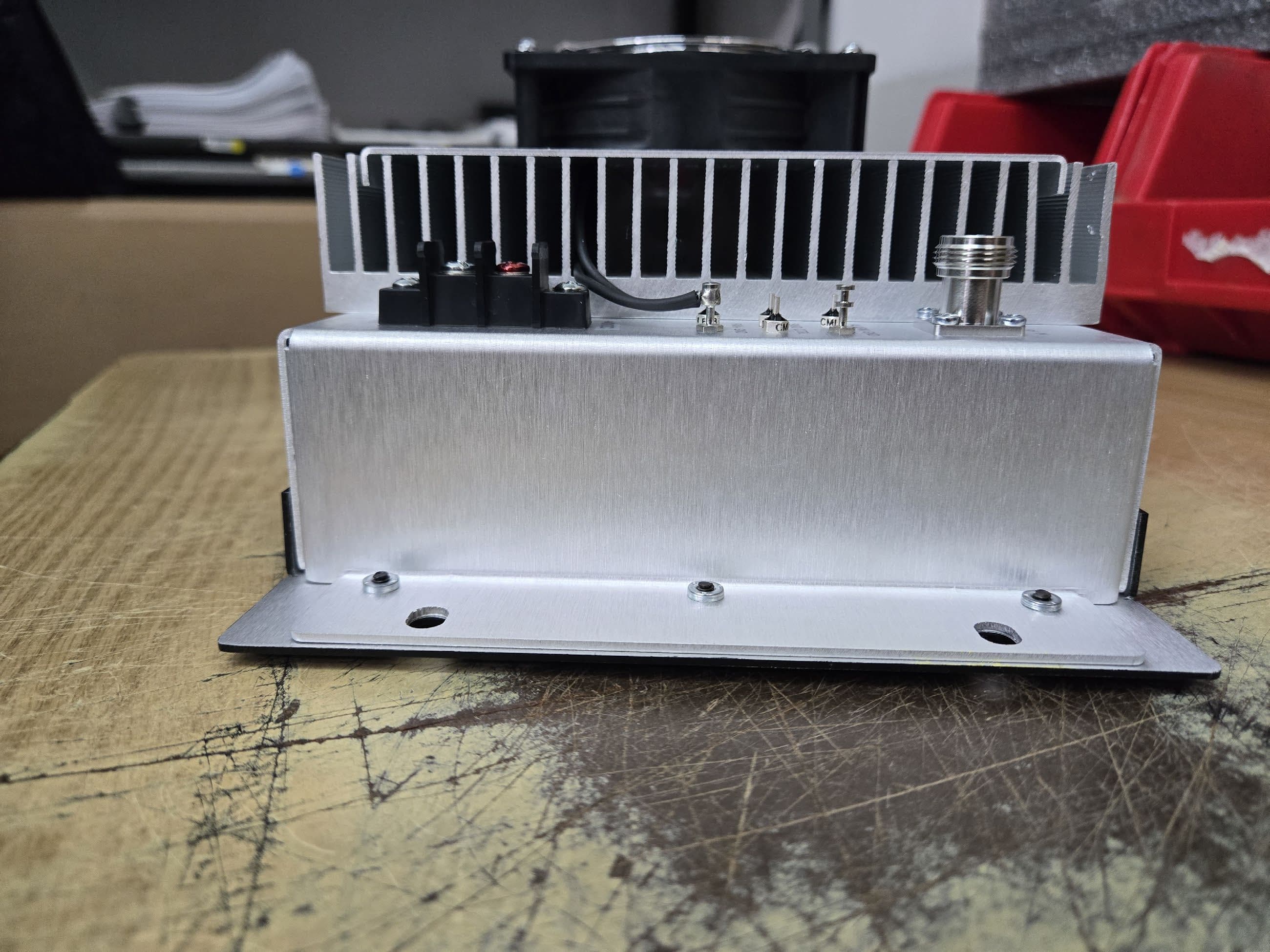
CWWP25XXDE4
Sep 17, 2025Power Amplifier AB to C Class
Equipment Class
B2I - Part 20 Industrial Booster (CMRS)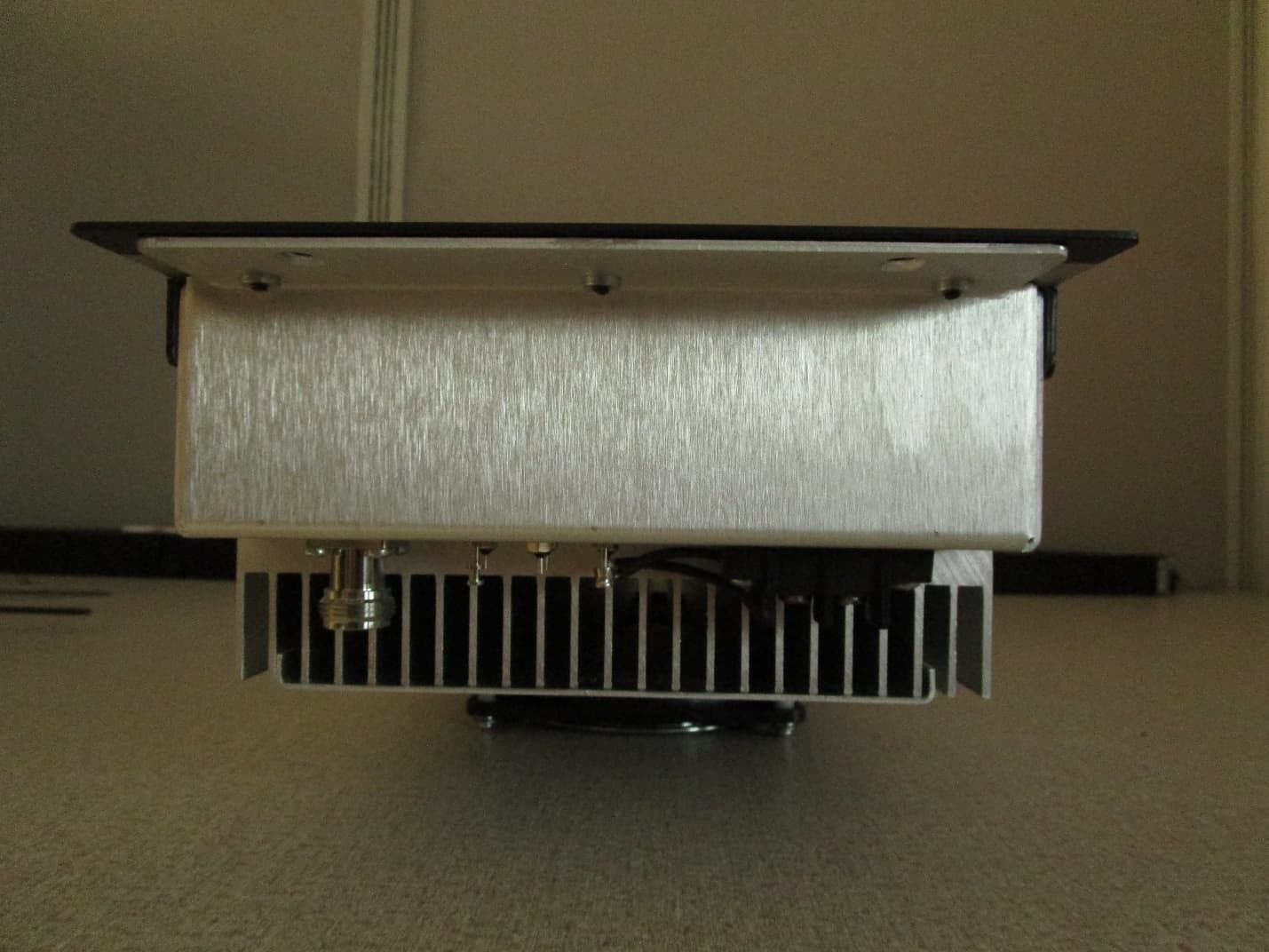
CWWP10XXDE1
Mar 10, 2020VHF AMPLIFIER
Equipment Class
B9B - Part 90 Class B Industrial Booster (non-SMR)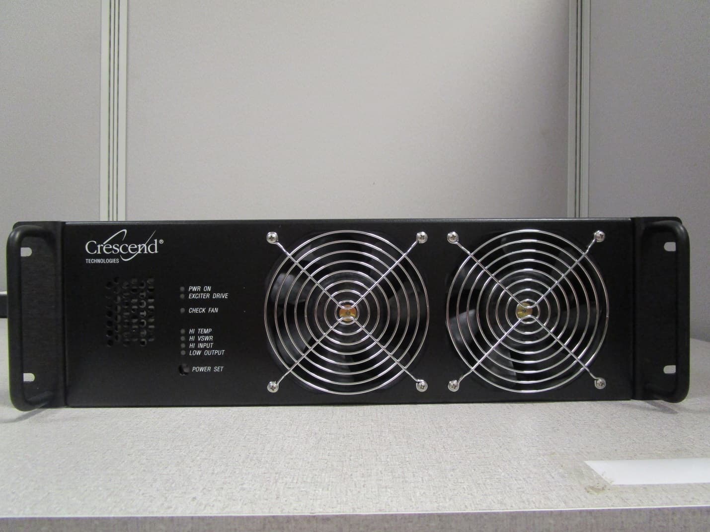
CWWP25XXHA3
Jan 27, 2020HIGH BAND HIGH POWER AMPLIFIER
Equipment Class
B9A - Part 90 Class A Industrial Booster (non-SMR)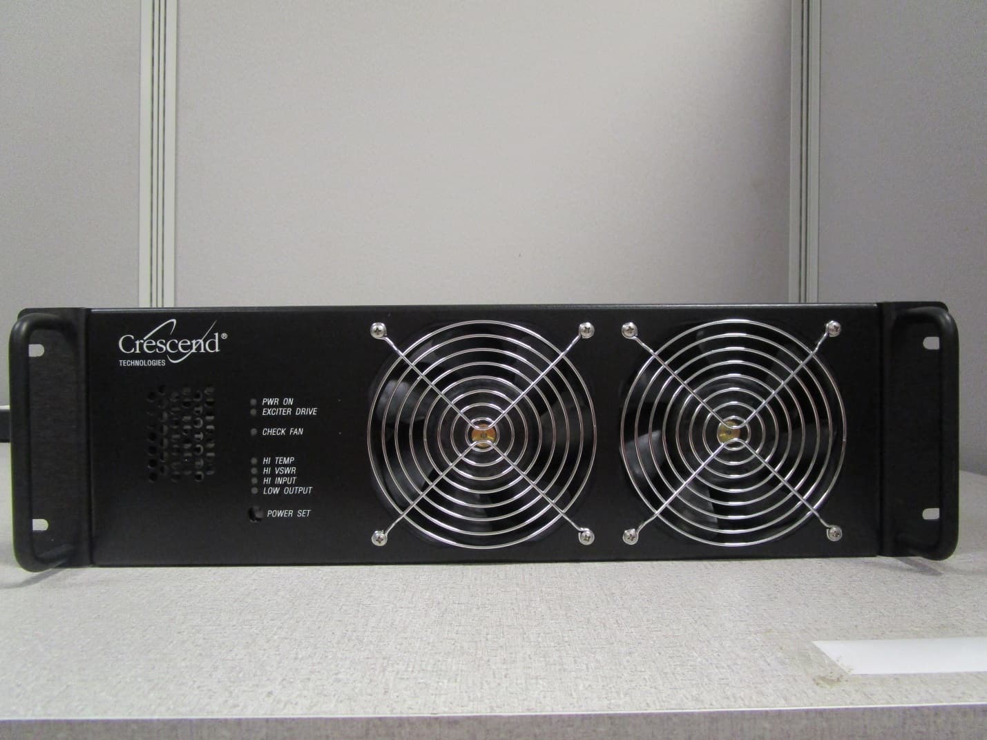
CWWP25XXGA3
Jan 21, 2020LOW BAND HIGH POWER AMPLIFIER
Equipment Class
B9A - Part 90 Class A Industrial Booster (non-SMR)
CWWP2RTK450
May 10, 201525Watt One-Way Amplifier
Equipment Class
AMP - Amplifier