D87-ZM5304-UZ-Wave Serial Interface Module with On-Board Antenna
Sigma Designs Inc
Click to zoom
Application Details
- Equipment Class
- DXX - Part 15 Low Power Communication Device Transmitter
- Date of Grant
- Aug 22, 2013
- Application Purpose
- Original Equipment
- Date of Application
- Aug 22, 2013
- Equipment Note
- Z-Wave Serial Interface Module with On-Board Antenna
- Frequency Range
- 908.40000000 - 916.00000000
- Company
- Sigma Designs Inc
- Country
- United States
Documents & Files
Document Text
Text extracted from the exhibit documents filed with the FCC. Open a document above to read the original.
Users Manual
DATASHEET: ZM5304 DSH12461-3 | 7/2013 1 FULLY INTEGRATED Z-WAVE® WIRELESS MODEM WITH ON-BOARD ANTENNA The Sigma Designs ZM5304 Modem is a fully integrated Z-Wave modem module in a small 27mmx15.2mmx5.5mm form factor. It is an ideal solution for home control applications such as access control, appliance control, AV control, building automation, energy management, lighting, security, and sensor networks in the “Internet of Things”. A baseband controller, sub-1 GHz radio transceiver, crystal, decoupling, SAW filter, matching, and the antenna is included to provide a complete Z-Wave solution to an application executing in an external host microcontroller. The ZM5304 Modem is certified with the FCC modular approval, ready to be used in any product without additional testing and license costs. The ZM5304 Modem is based on an 8-bit 8051 CPU core, which is optimized to handle the data and link management requirements of a Z-Wave node. The UART or USB interface can be used to access the Z-Wave stack available in the on-chip Flash memory, or to easily upgrade the modem firmware. FCC ID TBD IC ID TBD Features Complete Z-Wave stack available over UART or USB 32kB of byte addressable NVM memory Fully Integrated crystal, EEPROM, SAW filter, matching circuit, and antenna Supply voltage range from 2.3V-3.6V for optional battery operation No external components required FCC modular approval CE self-certified ITU G.9959 compliant Radio Transceiver Receiver sensitivity with SAW filter down to -103dBm Transmit power with SAW filter up to +2dBm Z-Wave 9.6/40/100kbps data rates Supports all Z-Wave sub-1 GHz frequency bands (865.2-926.3 MHz) Supports multi-channel frequency agility and listen before talk Regulatory Compliance ACMA: AS/NZS 4268 CE: EN 300 220/489 FCC: CFR 47 Part 15 Modular Approval IC: RSS-GEN/210 MIC: ARIB STD-T108 Modem UART speed up to 230.4kbps USB 2.0 full speed Z-Wave serial API accessed over UART or USB Firmware upgradeable via UART or USB TX mode current typ. 40mA @ +2dBm RX mode current typ. 32mA Normal mode current typ. 15mA Sleep mode current typ. 2μA Less than 1ms cold start-up time Power-On-Reset / Brown-out Detector Datasheet: ZM5304 2 DSH12461-3 | 7/2013 1 C ON T EN T 2 OVERVIEW .......................................................................................................................................................................... 4 2.1 PERIPHERALS ........................................................................................................................................................................... 4 2.1.1 Advanced Encryption Standard Security Processor ..................................................................................................... 4 2.1.2 Analog-to-Digital Converter ........................................................................................................................................ 5 2.1.3 Crystal Driver and System Clock .................................................................................................................................. 5 2.1.4 Interrupt Controller ..................................................................................................................................................... 5 2.1.5 Power-On-Reset / Brown-Out Detector ....................................................................................................................... 6 2.1.6 Reset Controller ........................................................................................................................................................... 6 2.1.7 Universal Asynchronous Receiver / Transmitter ......................................................................................................... 6 2.1.8 Universal Serial Bus ..................................................................................................................................................... 6 2.1.9 Watchdog .................................................................................................................................................................... 7 2.1.10 Wireless Transceiver.................................................................................................................................................... 7 2.2 MEMORY MAP ........................................................................................................................................................................ 7 2.3 MODULE PROGRAMMING .......................................................................................................................................................... 8 2.3.1 Entering In-System Programming Mode ..................................................................................................................... 8 2.3.2 Entering Auto Programming Mode ............................................................................................................................. 8 2.4 POWER SUPPLY REGULATOR ...................................................................................................................................................... 8 3 TYPICAL APPLICATION ........................................................................................................................................................ 9 4 PAD CONFIGURATION ....................................................................................................................................................... 10 4.1 PAD FUNCTIONALITY ............................................................................................................................................................... 10 5 ELECTRICAL CHARACTERISTICS .......................................................................................................................................... 12 5.1 TEST CONDITIONS ...........................................................…
Text truncated - open the document above for the full version.
Cover Letter(s)
Sigma Logo (not required) Emdrupvej 26A, 1., DK-2100 Copenhagen O, Demark Web Site: www.sigmadesigns.com Phone: +45 3913 004 FAX: +45 7020 9950 A G E N C Y A U T H O R I Z A T I O N L E T T E R FCC ID: D87-ZM5304-U Date: 2013.08.22 To whom it may concern: We, the undersigned, hereby authorize Bureau Veritas Consumer Products Services (H.K.) Ltd., Taoyuan Branch (BV CPS Taoyuan) of Taiwan to act on our behalf, as our agent, in the following matters related to the FCC approval of our products: report submittal, related correspondence, the signing of all documents relating to these matters, and any other lawful activity necessary to obtain such certification. Any act carried out by BV CPS Taoyuan within the scope of this authorization shall have the same effects as our own. This authorization shall expire 6 months from original date. If you have any questions regarding the authorization, please don’t hesitate to contact us. Thank you. Sincerely, Robert Pleva/ Director of Technical Marketing Sigma Designs, Inc TEL: 408-957-9767 Fax: 408-957-9741 E-Mail: [email protected]
Cover Letter(s)
FCC ID: D87-ZM5304-U Report No.: RF130710C16 Modular Approval Request Letter Bureau Veritas Consumer Products Services (H.K.) Ltd., Taoyuan Branch August 23, 2013 Dear Application Examiner, Sigma Designs, Inc., Z-Wave Serial Interface Module with On-Board Antenna, FCC ID: D87-ZM5304-U would like to have your authorization as a modular approval specific to the mobile RF exposure condition. The requirements of Public Notice DA00-1407 have been met and shown on the following statements. 1. “The modular transmitter must have its own RF shielding.” The radio portion of this module has been shielded, please see exhibition External Photo. 2. “The modular transmitter must have buffered modulation/data inputs.” The EUT has buffered data inputs, it is integrated in chip SD3503. 3. “The modular transmitter must have its own power supply regulation.” The part number of this regulator is SD3503. 4. “The modular transmitter must comply with the antenna requirements of section 15.203 and 15.204(C).” The EUT meets the FCC antenna requirements. The spurious emission, unique antenna connector and photo of antennas are shown in the test report. 5. “The modular transmitter must be tested in a stand-alone configuration” The EUT was tested in a stand-alone configuration via a USB extender. Please see section Photographs of Test Configuration in the test report, the EUT was plugged in this extender. 6. “The modular transmitter must be labeled with its own FCC ID number.” Please see exhibition Label Sample for the FCC ID of this module. And also in the exhibition Users Manual, there are instructions give to the OEM on how to label the end product. FCC ID: D87-ZM5304-U Report No.: RF130710C16 7. “The modular transmitter must comply with any specific rule or operating requirements applicable to the transmitter and the manufacturer must provide adequate instructions along with the module to explain any such requirements.” The EUT is compliant with all applicable FCC rules. Detail instructions for maintaining compliance are given in the Users Manual. 8. “The modular transmitter must comply with any applicable RF exposure requirements.” The EUT is compliant with all applicable RF exposure requirements. RF Exposure is addressed in the RF exposure exhibition. Please contact me if you have any further questions. Thanks for your attention. Best Regards, Robert Huang Senior Engineer Bureau Veritas Consumer Products Services (H.K.) Ltd., Taoyuan Branch
External Photos
Page 1 CONSTRUCTION PHOTOS OF EUT
ID Label/Location Info
Behind EUT Label sample Label location
Internal Photos
Page 2
Operational Description
FCC ID: D87-ZM5304-U Report No.: RF130710C16 Operational Description The transmitter of the EUT (Z-Wave Serial Interface Module with On-Board Antenna) is powered by 3.3Vdc from host equipment. The output power of this device is very low. Under normal use condition, the transmitter and the receiver are quite close, so high EIRP power is neither necessary nor allowed because of interference. For more detailed instruction, please take a look at the user’s manual.
Test Report
Report No.: RF130710C16 1 of 57 Report Format Version 5.0.0 FCC TEST REPORT REPORT NO.: RF130710C16 MODEL NO.: ZM5304-U FCC ID: D87-ZM5304-U RECEIVED: Jul. 10, 2013 TESTED: Jul. 19 ~ Aug. 07, 2013 ISSUED: Aug. 09, 2013 APPLICANT : Sigma Designs, Inc. ADDRESS : 1778 McCarthy Blvd., Milpitas, California, United States, 95035 ISSUED BY: Bureau Veritas Consumer Products Services (H.K.) Ltd., Taoyuan Branch LAB ADDRESS: No. 47, 14th Ling, Chia Pau Vil., Lin Kou Dist., New Taipei City, Taiwan ( R.O.C. ) TEST LOCATION: No. 19, Hwa Ya 2nd Rd, Wen Hwa Tsuen, Kwei Shan Hsiang, Taoyuan Hsien 333, Taiwan, R.O.C. This report is for your exclusive use. Any copying or replication of this report to or for any other person or entity, or use of our name or trademark, is permitted only with our prior written permission. This report sets forth our findings solely with respect to the test samples identified herein. The results set forth in this report are not indicative or representative of the quality or characteristics of the lot from which a test sample was taken or any similar or identical product unless specifically and expressly noted. Our report includes all of the tests requested by you and the results thereof based upon the information that you provided to us. You have 60 days from date of issuance of this report to notify us of any material error or omission caused by our negligence, provided, however, that such notice shall be in writing and shall specifically address the issue you wish to raise. A failure to raise such issue within the prescribed time shall constitute your unqualified acceptance of the completeness of this report, the tests conducted and the correctness of the report contents. Unless specific mention, the uncertainty of measurement has been explicitly taken into account to declare the com pliance or non-compliance to the specification. This report should not be used by the client to claim product certification, approval, or endorsement by TAF or any government agencies. Report No.: RF130710C16 2 of 57 Report Format Version 5.0.0 Table of Contents RELEASE CONTROL RECORD .............................................................................................................. 3 1. CERTIFICATION .......................................................................................................................... 4 2. SUMMARY OF TEST RESULTS ................................................................................................. 5 2.1 MEASUREMENT UNCERTAINTY .............................................................................................. 5 3. GENERAL INFORMATION .......................................................................................................... 6 3.1 GENERAL DESCRIPTION OF EUT ............................................................................................ 6 3.2 DESCRIPTION OF TEST MODES .............................................................................................. 6 3.2.1 TEST MODE APPLICABILITY AND TESTED CHANNEL DETAIL .............................................. 7 3.3 DESCRIPTION OF SUPPORT UNITS ........................................................................................ 8 3.3.1 CONFIGURATION OF SYSTEM UNDER TEST ......................................................................... 9 3.4 GENERAL DESCRIPTION OF APPLIED STANDARDS ............................................................. 9 4. TEST TYPES AND RESULTS ................................................................................................... 10 4.1 RADIATED EMISSION AND BAND EDGE MEASUREMENT .................................................. 10 4.1.1 LIMITS OF RADIATED EMISSION MEASUREMENT .............................................................. 10 4.1.2 TEST INSTRUMENTS ................................................................................................................ 11 4.1.3 TEST PROCEDURES ............................................................................................................... 12 4.1.4 DEVIATION FROM TEST STANDARD ..................................................................................... 12 4.1.5 TEST SETUP ............................................................................................................................. 13 4.1.6 EUT OPERATING CONDITIONS .............................................................................................. 13 4.1.7 TEST RESULTS ........................................................................................................................ 14 4.2 CONDUCTED EMISSION MEASUREMENT ............................................................................ 26 4.2.1 LIMITS OF CONDUCTED EMISSION MEASUREMENT ......................................................... 26 4.2.2 TEST INSTRUMENTS ............................................................................................................... 26 4.2.3 TEST PROCEDURES ............................................................................................................... 27 4.2.4 DEVIATION FROM TEST STANDARD ..................................................................................... 27 4.2.5 TEST SETUP ............................................................................................................................. 28 4.2.6 EUT OPERATING CONDITIONS .............................................................................................. 28 4.2.7 TEST RESULTS ........................................................................................................................ 29 4.3 RADIATED EMISSION MEASUREMENT (FOR 50dBc) ........................................................... 35 4.3.1 LIMITS OF RADIATED EMISSION MEASUREMENT .............................................................. 35 4.3.2 TEST INSTRUMENTS ..............................................................................................…
Text truncated - open the document above for the full version.
Test Setup Photos
1 PHOTOGRAPHS OF THE TEST CONFIGURATION CONDUCTED EMISSION TEST 2 3 RADIATED EMISSION TEST 4
Contact Information
Applicant
Robert Pleva(Director of Technical Marketing)
Test Firm
Bureau Veritas CPS (H.K.) Ltd., Taoyuan BranchRichard Chen
Technical Specifications
| # | Rule Parts | Frequency Range | Power Output |
|---|---|---|---|
| 1 | 15C | 908.4 MHz - 916 MHz | - |
Other Applications from Sigma Designs Inc
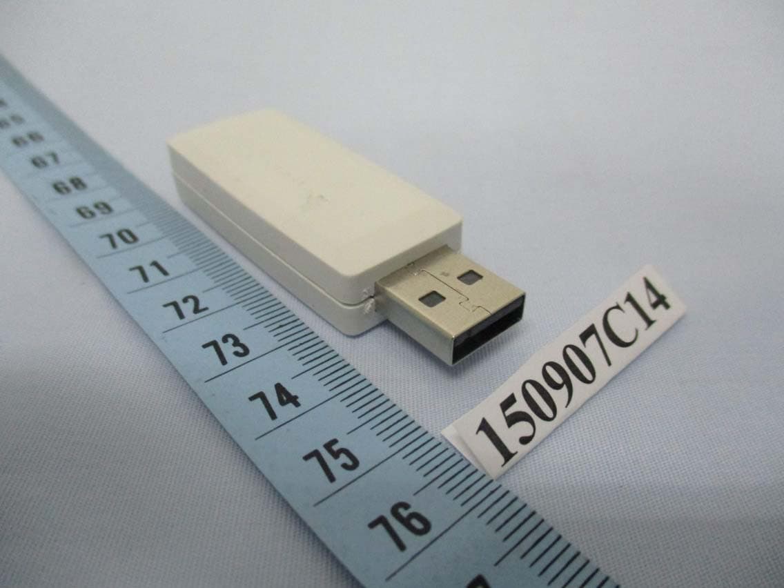
D87-UZB3-U
Oct 25, 2015Z-Wave USB Stick
Equipment Class
DXX - Part 15 Low Power Communication Device Transmitter
D87-SG-ZIRC3502
Aug 22, 2013Z-Wave & Infra Red Remote Control
Equipment Class
DXX - Part 15 Low Power Communication Device Transmitter
D87-SG-UZB3503
Aug 22, 2013Z-Wave USB Adapter
Equipment Class
DXX - Part 15 Low Power Communication Device Transmitter
D87-SG-ZIPR3503
Aug 22, 2013Z-Wave Over IP Gateway
Equipment Class
DXX - Part 15 Low Power Communication Device Transmitter
D87-SG-ZIRC
Sep 05, 2011ZIRC Z-Wave/Infra-red Audio Video Remote Control
Equipment Class
DXX - Part 15 Low Power Communication Device Transmitter