DCO-BN1-433AExpressGSM 433Tx/Rx Remote Controller BN1-433A
Alpha Arsenal LLC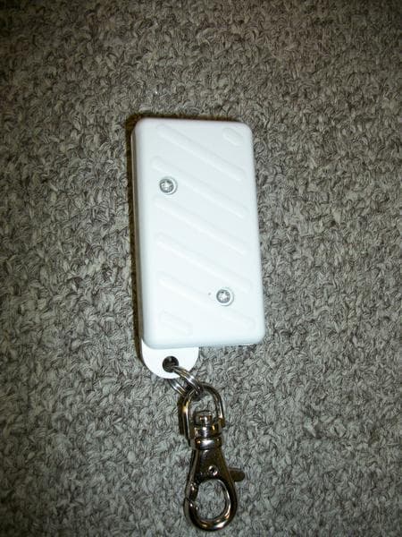
Click to zoom
Application Details
- Equipment Class
- DSR - Part 15 Remote Control/Security Device Transceiver
- Date of Grant
- May 08, 2012
- Application Purpose
- Original Equipment
- Date of Application
- May 08, 2012
- Equipment Note
- ExpressGSM 433Tx/Rx Remote Controller BN1-433A
- Frequency Range
- 434.50000000 - 434.50000000
- Company
- Alpha Arsenal LLC
- Country
- United States
Documents & Files
Document Text
Text extracted from the exhibit documents filed with the FCC. Open a document above to read the original.
Users Manual
User manual 2 Dear customer! Thank you for choosing our product. The efforts of different specialists of “Siberian Arsenal” scientific production association were put into creation of the modern high-quality technical security devices. Please look through this manual so that the device could serve for a long time and failure- free. In case you have any wishes or comments please use contact information given at the end of manual. W e appreciate your opinion. This user’s manual is intended for mounting and maintenance of GSM motion detector «EXPRESS GSM». The motion detector is designed to detect human movement within the protected premises and inform the user by GSM network about this. Protection mode is turned on/off by using the remote controller. The battery provides continuous operation of motion detector with a daily turning on/off the protection mode, from 6 to 12 months. Telephone number of the GSM motion detector SIM card: 3 Have you ever thought that set the alarm is expensive and troublesome, we also thought so! Now everything has become much easier. If you decide to protect yourself from the troubles, it would take only 10 minutes! Be sure you can handle easily! You rent a flat, and have no possibility to equip it with alarm. Set up the EXPRESS. W hen you move you can easily take it with you! In summer period burglaries become more frequent. You do not want to get into this unhappy statistics, but want to relax in the countryside. Set up the EXPRESS and relax with peace of mind! You build a house or a flat, no guard yet, but the valuables are already there. Set up temporarily the EXPRESS! You think your colleagues look at your table (cabinet). Follow up question by the EXPRESS! You already have protection with security office, but you think they could come to you when you are absent. Set up the EXPRESS and be sure! EXPRESS does not detect the movement of people through the glass, so the false alarms are impossible. Put it on a seat in the car when you leave to the store or to work! You are a builder and your facility has cabins and rooms, where you store valuables, construction equipment. Set up the EXPRESS! There is a watchman In your cottage community, negotiate with your neighbors and organize a real security, let the calls and SMS of the "Alert" come to the watchman and to you. Set up the EXPRESS! If you have reason to worry for the safety of your property, set up the EXPRESS GSM! 4 Settings For setting motion detector you will need: - SIM card with balance. PIN code request should be disabled; - Mobile telephone; - Remote controller; - motion detector; - Battery. For your ease you should record motion detector SIM card telephone number into your telephone book, for example «Cottage guard». Then in case you get alarm message, you will not guess who sent it. Helpful recommendations 1. Before operation in winter in unheated rooms it is desirable to install a new battery. 2. When replacing the battery installed options are remained. 3. It is advisable to use new SIM card for installation to motion detector. 4. It is desirable that the mobile operator of motion detector and your mobile operator coincide. This will speed up the transfer of SMS messages 5. Use tariff rate with the lowest cost of SMS messages. 6. Motion detector memory can store up to 6 remote controllers and up to 6 telephone numbers for warning. 7. Make sure that the place of motion detector installation has coverage area of cellular communication. 8. Receive or not receive the SMS with notification about turning on/off the protection 5 ! mode? Just change the jumper setting (see page 7). 9. Every 7 days you will receive test SMS messages with balance. 10. If you did not manage to record remote controller in motion detector’s memory or call the number of motion detector within defined period, remove the battery from the motion detector, wait 2-3 minutes. Then insert the battery observing the polarity, wait 30 seconds and record the remote controller or call motion detector number. 11. In case you changed SIM card, you should repeat the setting. 12. If you can not set the motion detector, make sure that - SIM card is installed correctly (see page 7); - jumper is in position 1 or 2 (see page 7); - the battery is installed with the correct polarity. 13. For more information you can read the manual on the site www.arsenal-npo.ru, in the Documentation section. Remember! The battery has a limited resource, so please use the economy mode. Attention! DO NOT REMOVE the SIM card when battery is installed. 6 For the initial setup of motion detector please follow several simple operations. 1 1.Remove the screw at the bottom part. 2. Remove the motion detector cap. 7 ! 2 Insert the SIM card into its holder. Set the jumper in position 1 or 2. 1. Normal mode. Set the jumper to the "S" position. You will receive SMS informing about turning on/off the protection mode. Protection mode can be turned off by remote controller in any time. 2. Economy mode. Remove the jumper. You will not receive SMS informing about turning on/off the protection mode. Turning off the protection mode will be possible after you get to detection zone. 3. GSM LED (Light-emitting diode). If the SIM card was used in the motion detector earlier, erase phone book. For this, please set the jumper to the "R" position, then MUST WAIT FOR 1 MINUTE and install the battery, observing polarity. Wait for the beep noise finish. Erasing completed. Remove the battery. Set the jumper in position 1 or 2. 8 3 Insert the battery into the motion detector slot observing polarity. At power-up, an audible beep sounds. Then three short beeps sound and the LED winks 1 time in 5 seconds. WARNING! Within 30 seconds after this you should record a phone number in motion detector memory (see next. page). 9 4 After 3 short beeps sound, during 30 seconds you should send SMS with your cell phone number to motion detector SIM card number in format: 1)+XXXXXXɏXXXX, where 1) – index number,…
Text truncated - open the document above for the full version.
Cover Letter(s)
ALPHA ARSENAL LLC. 910 Foulk Road, Suite 201, Wilmington, New Castle County, DE 19803 tel.: +1718-825-6292 emai: [email protected] March 21, 2012 Compliance Certification Services Certification Division 561F Monterey Road Morgan Hill, CA 95037 To whom it may concern: We, the undersigned, hereby authorize Advanced Compliance Laboratory, Inc., to act on our behalf in all manners relating to application for equipment authorization, including signing of all documents relating to these matters. Any and all acts carried out by Advanced Compliance Laboratory, Inc. on our behalf shall have the same effect as acts of our own. We, the undersigned, hereby certify that we are not subject to a denial of federal benefits, that includes FCC benefits, pursuant to Section 5301 of the Anti-Drug Abuse Act of 1988, 21 U.S.C. 853(a). In authorizing Advanced Compliance Laboratory, Inc. as our agent, we still recognize that we are responsible to: • comply with the relevant provisions of the certification program; • make all necessary arrangements for the conduct of the evaluation, including provision for examining documentation and access to all areas, records (including internal audit reports) and personnel for the purposes of evaluation (e.g. testing, inspection, assessment, surveillance, reassessment) and resolution of complaints; • make claims regarding certification only in respect of the scope for which certification has been granted; • do not use our product certification in such a manner as to bring the Certification Division into disrepute and not make any statement regarding our product certification which the Certification Division may consider misleading or unauthorized; • upon suspension or cancellation of certification, discontinue use of all advertising matter that contains any reference thereto and return any certification documents as required by the Certification Division; • use certification only to indicate the products are certified as being in conformity with specified standards; • endeavor to ensure that no certificate or report nor any part thereof is used in a misleading manner; • ensure that any reference to our product certification in communication media such as documents, brochures or advertising, complies with the requirements of the Certification Division; • keep a record of all complaints made known to the us relating to the product's compliance with requirements of the relevant standard and to make these records available to the Certification Division when requested; • take appropriate action with respect to such complaints and any deficiencies found in products or services that affect compliance with the requirements for certification; • document the actions taken. This authorization is valid until further written notice from the applicant. Sincerely Yours, Signature: Printed Name: Sergey Medvedev Title: General Manager Company: Alpha Arsenal LLC
Cover Letter(s)
March 21, 2012 Subject: FCC Confidentiality Request for FCC ID: DCO-BN1-433A To Whom It May Concern: Please accept this letter as an official request to have all Schematics, Bill of Materials, Block Diagrams and Methods of Operation of the DCO-BN1-433A, Express GSM Remote Controller application treated as confidential. This request is made pursuant to 47 CFR Section 0.457(d) of the Commission's Rules, and Section 552(b)(4) of the Freedom of Information Act. The information contained within represents many hours of engineering and design that should remain confidential as to protect our company's intellectual property and investments. Sincerely, Signature: Printed Name: Sergey Medvedev Title: General Manager Company: Alpha Arsenal LLC ALPHA ARSENAL LLC. 910 Foulk Road, Suite 201, Wilmington, New Castle County, DE 19803 tel.: +1718-825-6292 emai: [email protected]
External Photos
23 Figure 7.1 Front View 24 Figure 7.2 Rear View
ID Label/Location Info
8 2. PRODUCT LABELING Figure 2.1 FCC ID Label Figure 2.2 Location of Label on the Side of EUT Figure 2.2 FCC ID Label Location FCC ID: DCO-BN1-433A This device complies with part 15 of the FCC Rules. Operating is subject to the following two conditions: (1) This device may not cause harmful interference, and (2) this device must accept any interference received, including interference that may cause undesired operation. Figure 2.1 FCC ID Label FCC Label
Internal Photos
25 Figure 7.3 Cover opened_ Inside View 26 Figure 7.4 Component Side 27 Figure 7.5 Foil Side
Test Report
1 ELECTROMAGNETIC EMISSION COMPLIANCE REPORT of Express GSM MODEL: BN1-433A FCC ID: DCO-BN1-433A April 09, 2012 This report concerns (check one): Original grant x Class II change Equipment type: Low Power Intentional Radiator Deferred grant requested per 47 CF 0.457(d)(1)(ii)? yes no x If yes, defer until: (date) Company agrees to notify the Commission by (date) of the intended date of announcement of the product so that the grant can be issued on that date. Transition Rules Request per 15.37? yes no x If no, assumed Part 15, Subpart B for unintentional radiators - the new 47 CFR [10-1-90 Edition] provision. Report prepared for: ALPHA ARSENAL LLC Report prepared by: Advanced Compliance Lab Report number: 0048-120315-01 The test result in this report IS supported and covered by the NVLAP accreditation 6 Randolph Way Hillsborough, NJ 08844 Tel: (908) 927 9288 Fax: (908) 927 0728 Advanced Compliance Laboratory 2 Table of Contents Report Cover Page ..................................................................................................... 1 Table of Contents ....................................................................................................... 2 Figures ........................................................................................................................ 3 1. GENERAL INFORMATION ........................................................................................................... 4 1.1 Verification of Compliance .............................................................................................. 4 1.2 Equipment Modifications ................................................................................................. 5 1.3 Product Information ......................................................................................................... 6 1.4 Test Methodology ............................................................................................................ 6 1.5 Test Facility ..................................................................................................................... 6 1.6 Test Equipment ................................................................................................................ 6 1.7 Statement for the Document Use ...................................................................................... 7 2. PRODUCT LABELING .................................................................................................................. 8 3. SYSTEM TEST CONFIGURATION............................................................................................... 9 3.1 Justification...................................................................................................................... 9 3.2 Special Accessories .......................................................................................................... 9 3.3 Configuration of Tested System........................................................................................ 9 4. SYSTEM SCHEMATICS ................................................................................................................ 14 5. CONDUCTED EMISSION DATA .................................................................................................. 15 5.1 Test Methods and Conditions ........................................................................................... 15 5.2 Test Data ......................................................................................................................... 15 6. RADIATED EMISSION DATA ...................................................................................................... 18 6.1 Field Strength Calculation ............................................................................................... 18 6.2 Test Methods and Conditions ........................................................................................... 18 6.3 Test Data ......................................................................................................................... 18 6.4 Occupied Bandwidth ........................................................................................................ 20 7. PHOTOS OF TESTED EUT ............................................................................................................ 22 3 Figures Figure 2.1 FCC ID Label ........................................................................................... 8 Figure 2.2 Location of Label on Back of the EUT .................................................... 8 Figure 3.1 Radiated Test Setup, Position 1 ............................................................... 10 Figure 3.2 Radiated Test Setup, Position 2 ............................................................... 10 Figure 3.3 Radiated Test Setup, Position 3 ............................................................... 11 Figure 3.4 Conducted Test Setup, Front................................................................... 12 Figure 3.5 Conducted Test Setup, Rear .................................................................... 12 Figure 4.1 EUT Schematics ....................................................................................... 13 Figure 5.1 Line Conducted ........................................................................................ 15 Figure 5.2 Neutral Conducted .................................................................................. 16 Figure 6.1 Bandwidth Plot ........................................................................................ 19 Figure 6.2 Pulse Train ............................................................................................... 20 Figure 7.1 Front View ................................................................................................ 21 Figure 7.2 Rear View ................................................................................................. 22 Figure 7.3 Cover Opened_ Inside V…
Text truncated - open the document above for the full version.
Test Setup Photos
10 Figure 3.1 Radiated Test Setup, position 1-X 11 Figure 3.2 Radiated Test Setup, position 2-Y 12 Figure 3.3 Radiated Test Setup, position 3-Z
Contact Information
Applicant
Sergey Medvedev(General Manager)
Test Firm
Advanced Compliance LaboratoryWei Li
Technical Specifications
| # | Rule Parts | Frequency Range | Power Output |
|---|---|---|---|
| 1 | 15.231 | 434.5 MHz - 434.5 MHz | - |
Other Applications from Alpha Arsenal LLC

DCO-BN-3S-33
Oct 06, 2014Remote Controller BN-3S-33V (BN-3S-33RC)
Equipment Class
DSC - Part 15 Security/Remote Control Transmitter
DCO-EXPRESS-E3
Jan 07, 2013GSM Motion Detector Express-E3 GSM unit
Equipment Class
DSR - Part 15 Remote Control/Security Device Transceiver
DCO-EXPRESSGSM2
Aug 27, 2012Express GSM2 GSM Unit EXPRESSGSM2
Equipment Class
DSR - Part 15 Remote Control/Security Device Transceiver
DCO-BN3-433A
Aug 27, 2012Express GSM2 Remote Control BN3-433A
Equipment Class
DSR - Part 15 Remote Control/Security Device Transceiver
DCO-SN1-A
Aug 13, 2012EXPRESSGSM2 SIREN SN1-A
Equipment Class
DSR - Part 15 Remote Control/Security Device Transceiver