DGZPE0006535 Circuit Digital Control
Intermatic Inc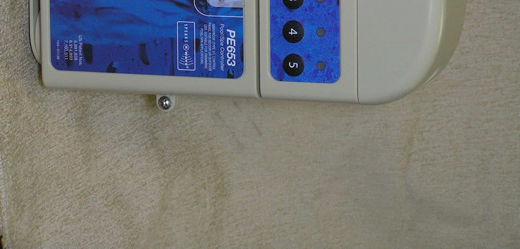
Click to zoom
Application Details
- Equipment Class
- DXT - Part 15 Low Power Transceiver, Rx Verified
- Date of Grant
- Apr 13, 2010
- Application Purpose
- Original Equipment
- Date of Application
- Apr 13, 2010
- Equipment Note
- 5 Circuit Digital Control
- Frequency Range
- 908.40000000 - 908.40000000
- Company
- Intermatic Inc
- Country
- United States
Documents & Files
Document Text
Text extracted from the exhibit documents filed with the FCC. Open a document above to read the original.
Users Manual
2 Multi-Wave PE653-PE953 Installation Guide Copyright © 2010 Intermatic, Inc. Important Safety Instructions All electrical work must be performed by a licensed electrician and conform to all national, state, and local codes. When installing and using this electrical equipment, basic safety precautions should always be followed, including the following: DANGER: To reduce the risk of injury, do not remove the suction fittings of your spa or hot tub. Never operate a spa or hot tub if the suction fittings are broken or missing. Never replace a suction fitting with one rated less than the flow rate marked on the equipment assembly. WARNING: Prolonged immersion in hot water may induce hyperthermia. Hyperthermia occurs when the internal temperature of the body reaches a level several degrees above the normal body temperature of 98.6°F. The symptoms of hyperthermia include dizziness, fainting, drowsiness, lethargy, and an increase in the internal temperature of the body. The effects of hyperthermia include: 1) unawareness of impending danger; 2) failure to perceive heat; 3) failure to recognize the need to exit spa; 4) physical inability to exit spa; 5) fetal damage in pregnant women; 6) unconsciousness resulting in a danger of drowning. WARNING: To Reduce the Risk of Injury — The water in a spa should never exceed 104°F (40°C). Water temperatures between 100°F • (38°C) and 104°F (40°C) are considered safe for a healthy adult. Lower water temperatures are recommended for young children and when spa use exceeds 10 minutes. Since excessive water temperatures have a high potential for causing fetal damage during • the early months of pregnancy, pregnant or possibly pregnant women should limit spa water temperatures to 100°F (38°C). Before entering a spa or hot tub, the user should measure the water temperature with an • accurate thermometer since the tolerance of water temperature-regulating devices varies. The use of alcohol, drugs, or medication before or during spa or hot tub use may lead to • unconsciousness with the possibility of drowning. Obese people and people with history of heart disease, low or high blood pressure, • circulatory system problems, or diabetes should consult a physician before using a spa. People using medication should consult a physician before using a spa or hot tub since some • medication may induce drowsiness while other medication may affect heart rate, blood pressure, and circulation. WARNING: Risk of electric shock – Install the control center at least five (5) feet (152.4cm) from the inside wall of the pool and/or hot tub using non-metallic plumbing. Canadian installations must be at least three (3) meters from the water. Safety 3 Providing a brighter solution.™ • Children should not use spas or hot tubs without adult supervision. Do not use spas or hot tubs unless all suction guards are installed to prevent body and hair • entrapment. People using medications and/or having an adverse medical history should consult a • physician before using a spa or hot tub. People with infectious diseases should not use a spa or hot tub.• To avoid injury, exercise care when entering or exiting the spa or hot tub.• Do not use drugs or alcohol before or during the use of a spa or hot tub to avoid • unconsciousness and possible drowning Pregnant or possibly pregnant women should consult a physician before using a spa or hot • tub. Water temperature in excess of 100°F (38°C) may be injurious to your health.• Before entering a spa or hot tub measure the water temperature with an accurate • thermometer. Do nut use a spa or hot tub immediately following strenuous exercise.• Prolonged immersion in a spa or hot tub may be injurious to your health.• Do not permit any electric appliance (such as a light, telephone, radio, or television) within 5 • feet (1.5m) of a spa or hot tub. The use of alcohol, drugs or medication can greatly increase the risk of fatal hyperthermia in • hot tubs and spas. Water temperature in excess of 100°F (38°C) may be hazardous to your health.• WARNING: To reduce the risk of electrical shock, connect the grounding terminal in the metal enclosure to the grounding terminal of your electric service or supply panel with a continuous copper conductor having green insulation and one that is equivalent in size to the circuit conductors supplying this equipment. In addition, a second wire connector should be bonded with a no. 8 AWG (4.115mm) copper wire to any metal ladders, water pipes, or other metal within five (5) feet (1.52m) of the tub. WARNING: A ground-fault circuit-interrupter must be provided if this device is used to control underwater lighting fixtures. The conductors on the load side of the ground-fault circuit- interrupter shall not occupy conduit, boxes or enclosures containing other conductors unless the additional conductors are also protected by a ground-fault circuit-interrupter. Refer to local codes for complete details. 4 Multi-Wave PE653-PE953 Installation Guide Copyright © 2010 Intermatic, Inc. Contents Important Safety Instructions ........................................................................................................... 2 Section 1: System Overview ......................................................................................................... 8 Additional Detail on Key Components ......................................................................................... 9 Hand-Held Controller (PE953) ................................................................................................ 9 24-Volt Valve Actuator (PE24VA) ............................................................................................ 9 Water Temperature Sensor (PA122) ......................................................................................... 9 24-Volt Valve/Pump Switch (P4243ME) ................................................................................ 10 Optional — Freeze (Air Temperature) Sensor (178PA28A) .......…
Text truncated - open the document above for the full version.
Users Manual
Three: PE653 Receiving Device Installation 29 Providing a brighter solution.™ 240V 2-Speed pump + 240V Booster Pump + 240V Actuator + Heater Figure 3-16 30 Multi-Wave PE653-PE953 Installation Guide Copyright © 2010 Intermatic, Inc. 240V 2-speed pump + 120V lights + 240V blower + heater Figure 3-17 Three: PE653 Receiving Device Installation 31 Providing a brighter solution.™ 240V 2-speed pump + 240V blower + 240V actuator + heater Figure 3-18 32 Multi-Wave PE653-PE953 Installation Guide Copyright © 2010 Intermatic, Inc. 240V 2-speed pump + 240V booster pump + 240V blower + heater Figure 3-19 Three: PE653 Receiving Device Installation 33 Providing a brighter solution.™ 240V 2-speed pump + 240V booster pump + 120V light + heater Figure 3-20 34 Multi-Wave PE653-PE953 Installation Guide Copyright © 2010 Intermatic, Inc. 240V 2-speed pump + 240V booster pump + other 120 VAC equipment + heater Figure 3-21 Three: PE653 Receiving Device Installation 35 Providing a brighter solution.™ Low-Voltage Wiring Water Temperature Sensor The Multi-Wave Control System comes equipped with a Water Temperature Sensor. This sensor is needed to monitor both the pool and spa water temperature depending on the position of the diverter valves. It must be installed for the thermostat control to work. Power must be disconnected when connecting the temp sensor. Only an Intermatic Sensor will work with this controller. Follow these directions to install and mount the water temperature sensor. Drill a 3/8” hole in the pipe between the filter 1. pump and filter and install the Water Temperature Sensor with hose clamp (not provided). Ensure the O-ring is in place. Run the wire to the Receiving Device. Insert both 2. wires into the 3rd and 4th terminals on the sensor connection block and tighten the 3rd and 4th terminal block screws shown in Figure 3-22. Freeze/Air Temperature Sensor The Multi-Wave Control System uses an optional Freeze /Air Temperature Sensor (178PA28A) for measuring air temperature and implementing the Freeze Protection Circuit—necessary for the freeze protection circuit and programming to work. Power must be disconnected when connecting the Freeze / Air Temperature Sensor. Only an Intermatic Freeze / Air Temperature Sensor will work with this controller. Install the Freeze /Air Temperature Sensor outside 1. the Receiving Device, preferably onto a piece of conduit at or near your equipment pad. Use the clip provided with the sensor. Do not install in direct sunlight or around motors or other heat sources. Run the wire to the Receiving Device. There is a 2. connector at the end of the wires coming from the sensor. For installation onto the PE653, this connector will not be needed. Cut the connector off using a wire cutter, strip the wire ends, and insert both wires into the 1st and 2nd terminals on the sensor connection block and tighten the 1st and 2nd terminal block screws shown in Figure 3-23. Figure 3-22 Figure 3-23 36 Multi-Wave PE653-PE953 Installation Guide Copyright © 2010 Intermatic, Inc. Communications to a Variable-Speed Pump If the Multi-Wave system includes a variable-speed pump, you must wire the pump’s communications cable to the PE653 so the two devices can communicate. Connect one end of the control 1. cable to the proper terminals on the variable-speed pump. Refer to the manufacturer’s instructions. The pump manufacturer includes a cable with a plug for the motor. OBSERVE POLARITY. Connect the 2. other two wires to the wiring block at the far right of the top of the PE653. (Use the color code shown in Figure 3-4.) Motorized Valve Actuator Connection and Synchronizing The Multi-Wave Control System is capable of controlling Motorized Valve Actuators using Model P4243ME Valve/Pump Switch Mechanism. When used, the P4243ME must be installed in an enclosure that is separate from the PE653RC system. The P4243ME is prompted to position the 24 volt motorized actuators when the P /S (Pool / Spa) button is pushed on the PE953 Hand Held Transmitter. Figure 3-24 Figure 3-25 Three: PE653 Receiving Device Installation 37 Providing a brighter solution.™ The actuators must be installed to automatically rotate your valves between the pool and spa plumbing. The 24 VAC power for the Valve Actuators is produced by a transformer in the P4243ME. All power to both units must be turned OFF when connecting the black and white actuator control leads to the PE653 (see diagram above). Refer to the installation and wiring directions for the P4243ME Actuator Control and PE24VA Actuators for additional instructions for each unit. Remove power from the P4243ME and the Multi-Wave Receiving Device. Attach the valve actuators (PE24VA) to the water valves. (See instructions included with 1. actuators). Run the actuator cable(s) to the P4243ME control through the low voltage raceway.2. Remove the access door at the top right of the P4243ME mechanism. 3. Insert the three-pin connector of the motorized valve actuator to any of the three available 4. connectors on the P4243ME circuit board. Connect 120 or 240 VAC power leads to the correct colored wires of the P4243ME 5. transformer (see above). Connect the two Actuator Control wire leads as shown above in Figure 3-25.6. Apply power to both the PE653 and the P4243ME and synchronize the actuators as follows:7. Make sure that circuit number 4 is OFF (Green Load ON indicator is OFF). This indicates a. that the switch is in POOL mode. If either of the Actuators is positioned backwards, flip the switch on the back to reverse b. position. Turn circuit number 4 ON (Green Load ON indicator is ON). This indicates that the switch c. is in SPA mode. Verify that the Actuators are correctly synchronized with your installation.d. Fireman’s Switch Connection The Intermatic Multi-Wave Control System is capable of controlling most heaters or heat pumps in the market today. Circuit number 5 in the PE653 is configured to control the heater using the 24 VAC thermostatic circuitry. Locate your type …
Text truncated - open the document above for the full version.
Users Manual
Five: Everyday Use of the PE953 Hand-Held Controller 57 Providing a brighter solution.™ Manually Turning Equipment On and Off At the Receiving Device For service purposes, the five circuits and / or the pool/spa actuators can be operated manually at the PE653 Receiving Device. Simply press any of the circuit buttons on the PE653 Receiving Device to toggle between ON and OFF. Any manual OFF/ON circuit activation performed at the PE653 Receiving Device will be reflected on the screen of the Hand-Held Controller. 58 Multi-Wave PE653-PE953 Installation Guide Copyright © 2010 Intermatic, Inc. Section 6: Advanced Features The PE953 controller is able to listen to Z-Wave commands while the controller is awake. (For example: requesting the controller to report Version or Manufacturer Specific information.) To wake up the controller, press any key. Configuring Two or More Hand-Held Controllers Many installations will find it convenient to use two Hand-Held Controllers. Once you have linked and programmed one Hand-Held to the Receiving Device, it’s easy to add additional units. NOTES: The first Hand-Held you link to the Receiving Device is considered the PRIMARY control and all other Hand-Held units are SECONDARY. Only the PRIMARY Controller can be used to add or remove devices from a network in • the Intermatic Multi-Wave system. SECONDARY controllers cannot add or remove devices from the network in the • Intermatic Multi-Wave system — they can only control devices on the network. You can tell the status of a Hand-Held from the VER (version) code at the top right corner of the display on the programming screens: the letter “P” = PRIMARY; the letter “S” = SECONDARY. The PRIMARY control must be used to “introduce” or include any additional (SECONDARY) Hand-Held units to the system. If the PRIMARY Hand-Held must be replaced (due to loss, damage, etc.,), you must reprogram from scratch to create a new PRIMARY unit, then reprogram any additional Hand-Helds as SECONDARY controls. If necessary, press and release any button on the Hand-Held 1. Controller to wake it from sleep. If the screen is not displaying LEARN MODE, press and hold the <P/S> and <ENTER> buttons at the same time to put the device into programming mode. You are in programming mode when the LEARN MODE screen is displayed, as shown at the right. Press the 2. DOWN arrow button to view the CNTRL OPTION screen as shown Press the 3. <2> button to select CONTROLLER COPY. Six: Advanced Features 59 Providing a brighter solution.™ On the Primary Hand-Held used to set up and configure the 4. network, press and release the <3> button to select SEND NET AND CONFG. On the new Hand-Held you are adding to the network, follow Steps 1-3, then press and 5. release the <4> button to select RECV NET AND CONFG. The words INCLUDING DEVICE will appear at the bottom of the primary controller’s screen. The screen will briefly display the words SENDING NET INFO, then SENDING SCENE INFO, then SENDING CFG INFO during the transfer of info to the secondary device. After a few seconds the controller will return to the CNTRL COPY screen. The words WAITING FOR INCLUDE will appear at the bottom of the secondary controller’s screen. Upon completion of the info transfer the word SUCCESSFUL will then appear. After a few seconds the controller will return to the Main screen. On the new Hand-Held (secondary) controller, press and hold the 6. <P/S> and then the <ENTER> buttons to return to the LEARN MODE screen. You will notice the screen display will have the following differences: The letter “S” will show at the top right corner of the • screen following the version number, indicating that it is a secondary control. Selections 2 and 3 are now blank. These options are not • available on a secondary controller. Press the down arrow button to display the CNTRL OPTION 7. screen. Notice that items 2, 3 and 5 have been changed to show the options that a secondary remote can perform. Press the 8. <ENTER> button on both controls as necessary to return to the Main screen. NOTE: Any time you add something new to the network, you must repeat this procedure to copy the new item to all secondary Hand-Held Controllers. Otherwise, the secondary units will not know about the new item(s). 60 Multi-Wave PE653-PE953 Installation Guide Copyright © 2010 Intermatic, Inc. Changing a Secondary Remote Control into a Primary Control There are several situations where you might want to create a primary remote control out of a secondary control. For example, an installer might set up similar customer systems using a master Hand-Held Controller (already programmed), and then want to transfer primary status to the customer’s remote. The procedure is known as “shifting.” “Controller Shift” swaps the roles of the two Hand Held units involved. The Primary Controller will become a Secondary Controller and the Secondary will become the Primary Controller. NOTE: There can only be one Primary Controller in the network at a time. If necessary, press and release any button on both Hand-Held Controllers to wake them from 1. sleep. If the screens on both Hand-Held Controllers are not displaying LEARN MODE, press and hold the <P/S> and <ENTER> buttons at the same time on each to put the devices both into programming mode. You are in programming mode when the LEARN MODE screen is displayed. Press the 2. DOWN arrow button on each Hand-Held Controller to view the CNTRL OPTION screen. On the PRIMARY Hand-Held, press and release the 3. <3> button to select CONTROLLER SHIFT. Once the button is pressed on the controller, it displays PRESS BUTTON ON DEVICE TO INCLUDE INCLUDING DEVICE. On the SECONDARY Hand-Held (the one you are shifting to 4. PRIMARY status), press and release the <3> button to select RECEIVE NET AND CFG. Both Hand-Helds will restart, and when finished, the screen displays will have several differences: The words INCLUDING DEVICE will appear at the bottom • of the primary controller’s screen. The screen wil…
Text truncated - open the document above for the full version.
ID Label/Location Info
MODEL: PE653 5 CIRCUIT DIGITAL CONTROL FCC ID: DGZPE000653 IC: 4898A-P00653 This device complies with part 15 of the FCC rules. Operation of this device is subject to the following two conditions: (1) This device may not cause harmful interference, and (2) This device must accept any interference including interference that may cause undesired operation. SUITABLE FOR INDOOR AND OUTDOOR USE. INTERMATIC INC., Spring Grove, IL 60081-9698 www.intermatic.com 154--01021
ID Label/Location Info
1 2 3 4 5 6 TOP OF LABEL 7 CENTER LABEL ON BACK OF UNIT IN APPROXIMATE LOCATION AS SHOWN KEEPING LABEL STRAIGHT. BACK VIEW TOP OF LABEL 8 SEE NOTE 2 9 TOP OF LABEL TOP OF LABEL SEE NOTE 3 NOTES: 1) SECURE ITEM 1 TIGHTLY TO ITEM 2 USING ITEMS 3 & 4 AS SHOWN. 2) OPEN 5-CIRCUIT RECEIVER DOOR AND PLACE ITEM 8 ON INSIDE OF DOOR. THEN RESCREW DOOR SHUT. 3) OPEN DOOR ON METAL CASE AND PLACE ITEM 9 ON INSIDE OF DOOR. RJN NONE 1:3 2 MM 2-23-10 REV HEAT TREAT REVISED REVISION DESCRIPTION FINISH MAT'L NAME INTERMATIC INCORPORATED MODEL SUPERSEDES APPROVED DRAWN TOLERANCES: DECIMALS (UNLESS OTHERWISE SPECIFIED) - TWO PLACE (.00) + /- .015 - THREE (.000) +/- .005 ANGLES +/- 30 MINUTES - ALL DIMENSIONS MUST BE MET BEFORE PLATING SCALE: 193--00281A ENCL ASSY-PE653RC SEE B/M NONE ADDED ITEM 9 AND NOTE 3 2-23-10 RJN DO NOT REVISE RASTER FILE REVISE AGILE VENDOR DOCUMENT 193--00281A 2-23-10 DIMENSIONING SYSTEM: ALL DIMENSIONS ARE IN INCHES UNLESS OTHERWISE SPECIFIED -METRIC DIMS IN BRACKETS IF DUAL DIMENSIONED
Test Report
Engineering Test Report No. 0903403-01 Measurement of RF Interference from a Model PE653 Pool/Spa Controller Transceiver For : Intermatic 7777 Winn Road Spring Grove, IL 60081 P.O. No. : 910645 Date Tested : December 14 and 15, 2009 Test Personnel : Mark E. Longinotti Specification : FCC "Code of Federal Regulations” Title 47 Part 15, Subpart B, for receivers and Subpart C, Section 15.249 for Intentional Radiators Operating within the 902MHz to 928MHz band Industry Canada RSS-210 Industry Canada RSS-GEN Test Report By : Mark E. Longinotti Senior EMC Test Engineer Partially Witnessed by : Patrick Alog Intermatic Approved By : Raymond J. Klouda Registered Professional Engineer of Illinois - 44894 Elite Electronic Engineering Inc. 1516 Centre Circle Downers Grove, IL 60515 Tel : (630) 495-9770 Fax: (630) 495-9785 www.elitetest.com Engineering Test Report No. 0903403-01 THIS REPORT SHALL NOT BE REPRODUCED, EXCEPT IN FULL, WITHOUT THE WRITTEN APPROVAL OF ELITE ELECTRONIC ENGINEERING INCORPORATED. Page 2 of 45 TABLE OF CONTENTS PARAGRAPH DESCRIPTION OF CONTENTS PAGE NO. 1 INTRODUCTION ............................................................................................................................................... 4 1.1 Scope of Tests .......................................................................................................................................... 4 1.2 Purpose .................................................................................................................................................... 4 1.3 Deviations, Additions and Exclusions....................................................................................................... 4 1.4 EMC Laboratory Identification .................................................................................................................. 4 1.5 Laboratory Conditions .............................................................................................................................. 4 2 APPLICABLE DOCUMENTS ............................................................................................................................ 4 3 TEST ITEM SETUP AND OPERATION............................................................................................................ 5 3.1 General Description .................................................................................................................................. 5 3.1.1 Power Input .......................................................................................................................................... 5 3.1.2 Peripheral Equipment........................................................................................................................... 5 3.1.3 Interconnect Cables ............................................................................................................................. 5 3.1.4 Grounding............................................................................................................................................. 5 3.2 Operational Mode ..................................................................................................................................... 5 3.3 Test Item Modifications............................................................................................................................. 5 4 TEST FACILITY AND TEST INSTRUMENTATION..........................................................................................5 4.1 Shielded Enclosure................................................................................................................................... 5 4.2 Test Instrumentation ................................................................................................................................. 5 4.3 Calibration Traceability ............................................................................................................................. 5 4.4 Measurement Uncertainty ........................................................................................................................ 5 5 TEST PROCEDURES ....................................................................................................................................... 6 5.1 Powerline Conducted Emissions .............................................................................................................. 6 5.1.1 Receiver ............................................................................................................................................... 6 5.1.1.1 Requirements ............................................................................................................................... 6 5.1.1.2 Procedures ................................................................................................................................... 6 5.1.1.3 Results ......................................................................................................................................... 6 5.1.2 Transmitter ........................................................................................................................................... 7 5.1.2.1 Requirements ............................................................................................................................... 7 5.1.2.2 Procedures ................................................................................................................................... 7 5.1.2.3 Results ......................................................................................................................................... 7 5.2 Radiated Measurements .......................................................................................................................... 8 5.2.1 Receiver .......................................................................................................................................…
Text truncated - open the document above for the full version.
Test Setup Photos
Engineering Test Report No. 0903403-01 Page 13 of 45 Figure 2 Test Setup for Conducted Emissions Engineering Test Report No. 0903403-01 Page 14 of 45 Figure 3 Test Setup for Radiated Emissions – 30MHz to 1GHz – Horizontal Polarization Test Setup for Radiated Emissions – 30MHz to 1GHz - Vertical Polarization Engineering Test Report No. 0903403-01 Page 15 of 45 Engineering Test Report No. 0903403-01 Page 16 of 45 Figure 4 Test Setup for Radiated Emissions – 908MHz - Horizontal Polarization - Transmitter Test Setup for Radiated Emissions – 908MHz – Vertical Polarization - Transmitter Engineering Test Report No. 0903403-01 Page 17 of 45 Engineering Test Report No. 0903403-01 Page 18 of 45 Figure 5 Test Setup for Radiated Emissions, 1GHz to 10GHz – Horizontal Polarization Test Setup for Radiated Emissions, 1GHz to 10GHz – Vertical Polarization
Contact Information
Applicant
Kimberly Boland(Director of Engineering)
Test Firm
Elite Electronic Engineering Inc.Kevin Halpin
Technical Specifications
| # | Rule Parts | Frequency Range | Power Output |
|---|---|---|---|
| 1 | 15C | 908.4 MHz - 908.4 MHz | - |
Other Applications from Intermatic Inc
DGZALC24B
Mar 17, 2024Programmable Switches
Equipment Class
DTS - Digital Transmission System
DGZPE000953
Apr 13, 2010Hand Held Transceiver
Equipment Class
DXT - Part 15 Low Power Transceiver, Rx Verified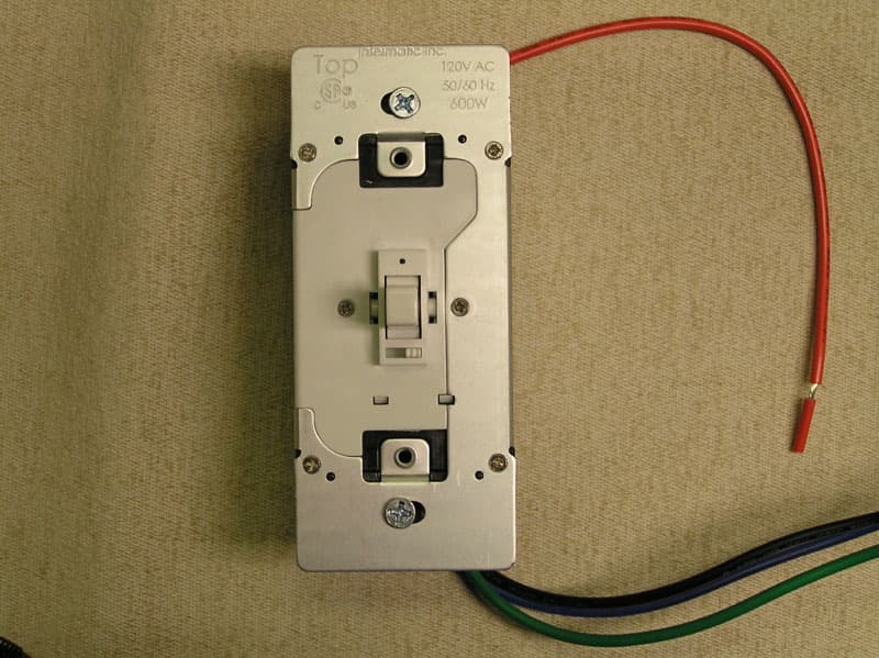
DGZHA000020P2
Mar 30, 2008In-Wall Toggle-Style Dimmer Switch
Equipment Class
DXX - Part 15 Low Power Communication Device Transmitter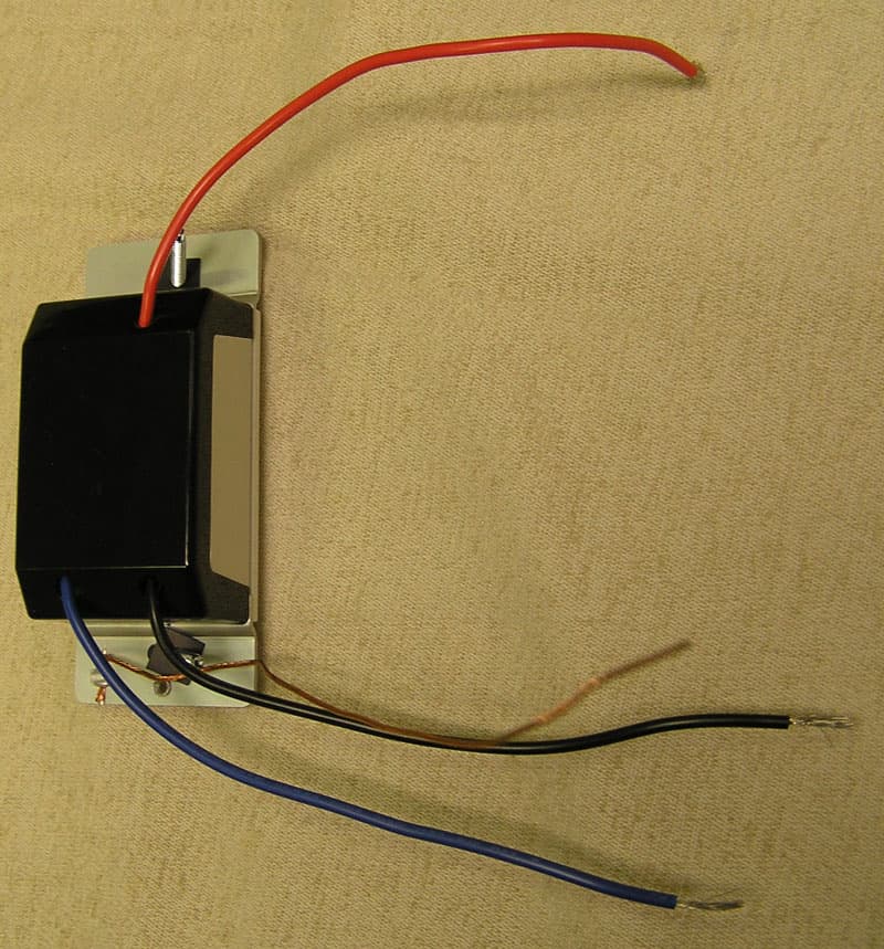
DGZHA000014P2
Mar 30, 2008In-Wall Dimmer Switch
Equipment Class
DXX - Part 15 Low Power Communication Device Transmitter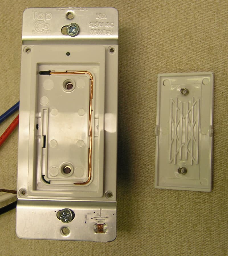
DGZHA000018P2
Mar 30, 2008In-Wall Switch
Equipment Class
DXX - Part 15 Low Power Communication Device Transmitter