DJ7-418100W EXTERNAL RF AMPLIFIER
Ten Tec Inc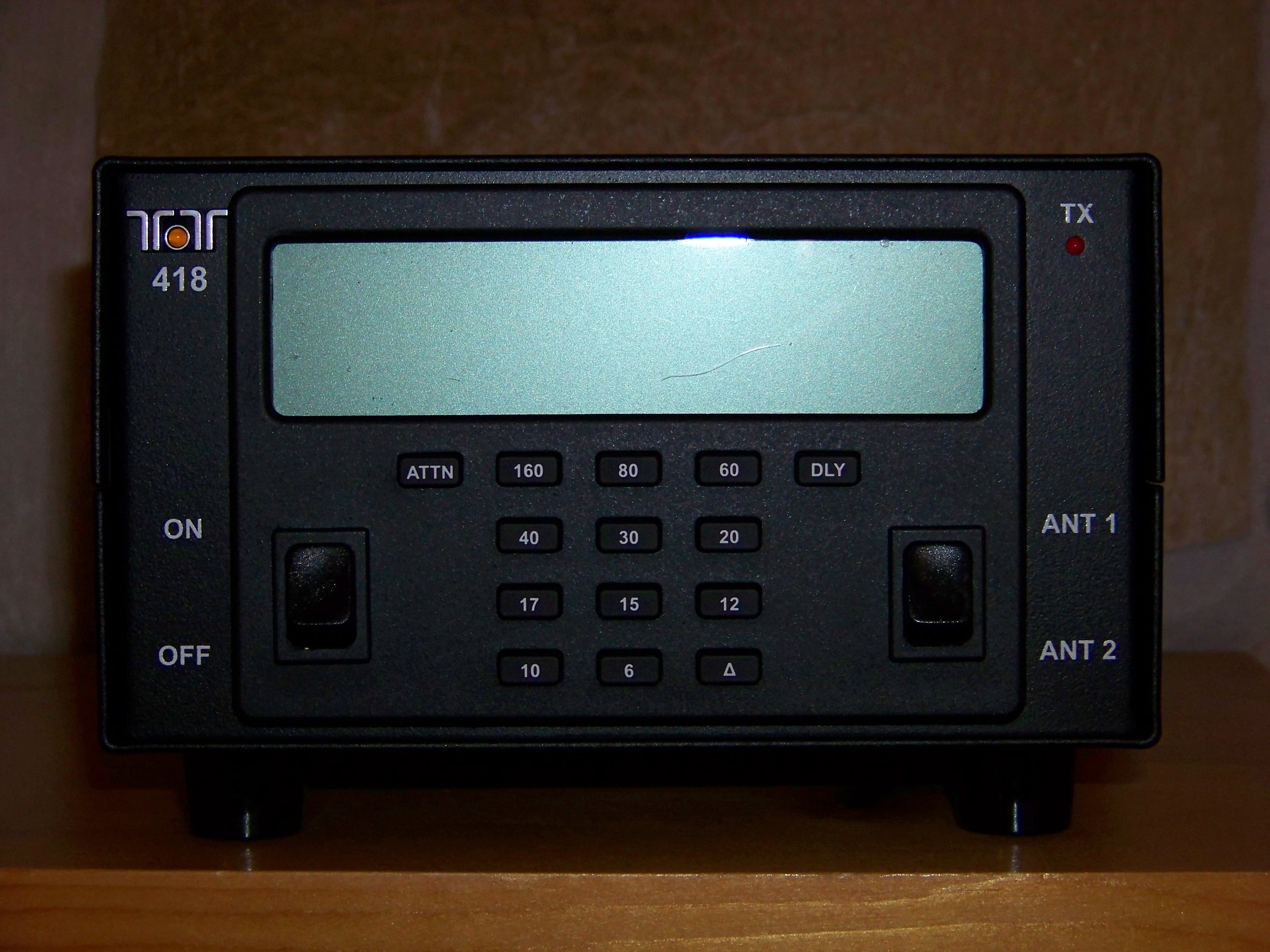
Click to zoom
Application Details
- Equipment Class
- AMP - Amplifier
- Date of Grant
- Mar 01, 2012
- Application Purpose
- Original Equipment
- Date of Application
- Mar 01, 2012
- Equipment Note
- 100W EXTERNAL RF AMPLIFIER
- Frequency Range
- 50.00000000 - 54.00000000
- Company
- Ten Tec Inc
- Country
- United States
Documents & Files
Document Text
Text extracted from the exhibit documents filed with the FCC. Open a document above to read the original.
Users Manual
418 Users manual Release 1.00 – NOVEMBER, 2011 Part #74468 Printed in USA 1 Table of Contents 1. Your new 418 ______________________________________________________________ 3 1.1. Unpacking 418 __________________________________________________________________ 3 1.2. About this Manual _______________________________________________________________ 3 1.3. Accessory package _______________________________________________________________ 3 1.4. Connection to Antenna & Power Supply_____________________________________________ 4 1.5. A word about grounding __________________________________________________________ 4 1.6. Philosophy of design _____________________________________________________________ 4 2. 418 FRONT PANEL ________________________________________________________ 6 2.1. Switches _______________________________________________________________________ 6 2.2. Band Buttons ___________________________________________________________________ 6 2.3. Attenuator Button _______________________________________________________________ 6 2.4. Delay Button____________________________________________________________________ 6 2.5. Delta Button ____________________________________________________________________ 6 2.6. Leds ___________________________________________________________________________ 6 2.7. Display ________________________________________________________________________ 6 2.8. Backlight _______________________________________________________________________ 6 3. 418 Rear Panel _____________________________________________________________ 7 3.1. ACC 1 _________________________________________________________________________ 7 3.2. Key In / Out ____________________________________________________________________ 8 3.3. Power _________________________________________________________________________ 8 3.4. Fuse ___________________________________________________________________________ 8 3.5. Antennas _______________________________________________________________________ 8 4. Amplifier Hookup __________________________________________________________ 9 4.1. 418 to 539 ______________________________________________________________________ 9 4.2. 418 to other _____________________________________________________________________ 9 5. Fault ____________________________________________________________________ 11 5.1. Fault conditions ________________________________________________________________ 11 5.2. List of faults ___________________________________________________________________ 11 6. Specifications _____________________________________________________________ 12 7. Block Diagram ____________________________________________________________ 13 8. In Case of Difficulty________________________________________________________ 14 9. Warranty & Return Policy ___________________________________________________ 14 418 Users manual Release 1.00 – NOVEMBER, 2011 Part #74468 Printed in USA 2 NOTES: 418 Users manual Release 1.00 – NOVEMBER, 2011 Part #74468 Printed in USA 3 1. Your new 418 1.1. Unpacking 418 Examine the 418 for signs of shipping damage. Should any damage be apparent, notify the delivering carrier immediately, stating the full extent of the damage. Save all damaged cartons and packing material. Liability for any shipping damage rests with the shipping carrier. 1.2. About this Manual A complete description of the features and functions on the 418 is included within the pages of this manual. The latest version of the 418 manual is also available for viewing at www.TENTEC.com. You may also find a full set of schematic diagrams at this same web location. 1.3. Accessory package The additional hardware and accessories listed in Fig 1.3-1 come standard with your new 418.Look over the items listed and refer to the 5 digit TEN-TEC part number and description should you find the need to replace an accessory. To purchase additional accessories and parts or to report an item missing from this list, please contact Service at TEN-TEC, INC. Qty Part # Description 1 46216 3.5mm to 2 RCA jacks cable 1 27091 Auto Style Fuse, 25 Amp 32V 1 35241 8 PIN DIN Connector 1 35263 Plug – Stereo, 3.5MM (1/8) 1 46174 8 PIN DIN TO 8 PIN DIN cable 2 41073 Fork Terminal 1 46214 Power Cable 1 74020 Warranty card 1 74244 Standard Warranty Sheet 1 74468 Manual for 418 1 74450 How do I become a Ten-Tec Ambassador Table 1.3-1 418 Packing List 418 Users manual Release 1.00 – NOVEMBER, 2011 Part #74468 Printed in USA 4 1.4. Connection to Antenna & Power Supply The 418 is designed for use with any antenna system providing 50 Ohm resistive impedance at the desired operating frequency. Every effort should be made to ensure the impedance of the antenna system is as close as possible to the specified 50-Ohm value. Note: that the “G5RV” type antenna and some Windom’s do not provide 50-Ohm impedance on all HF Amateur bands, and an external wide-range antenna coupler may be needed with this type antenna. Any antenna to be used with the 418 must, ultimately, be fed with 50 Ohm coaxial cable. The 418 requires a source of well-filtered and regulated DC voltage. The supply voltage on the 418 is 13.8 Vdc nominal +/- 15% to allow for mobile and battery operation. The voltage source must be capable of supplying 23 amperes continuous duty. The model 940 or 941 TEN-TEC power supplies will meet or exceed your voltage and current requirements. We recommend using the included DC power cable (P/N 46214). Use of #12 stranded wire is recommended for mobile and in home use to accommodate the required current demand during transmit. Note: Always enable the power source first and then the amplifier. If a generator or battery connected to a charger is used to supply the DC source, always turn off the amplifier before starting or shutting off the DC source equipment. These recharging devices often generate large voltage spikes that can damage the amplifier. 1.5. A word about grounding A good ground system is essential for optimum operation …
Text truncated - open the document above for the full version.
Block Diagram
Block Diagram 13.8VDC + - POWER RELAY ANT6ANT2ANT1RADIO ANTENNA RELAYS T/R RELAYS ATTENUATOR POWER AMPLIFIER LOW PASS FILTERS KEY ACC 1 REGULATORS IN/OUT CPU LOWPASS FILTER FRONT PANEL DISPLAY KEY PAD POWER SWITCH ANTENNA SWITCH EEPROM PIC IC(DISPLAY) 2 CLK,DAT,ENA(KEYPAD) POWER RELAYFAN CONTROL CONTROL 5V,3.3V C L K , D A T , E N A TEMP,Ic,E NA TEMP,Ic,ENA I/O REAR PANEL KEY IN,KEY OUT PWR RLY CONTROLFAN CONTROL 1/8" JACK 8 PIN DIN
Cover Letter(s)
Federal Communications Commission Authorization and Evaluation Division 1435 Oakland Mills Road Columbia, MD 21046 Date: February 10, 2012 SUBJECT: FCC Application for DJ7-418 To Whom It May Concern: We, the undersigned, hereby attest to the fact that we will apply the Declaration of Conformity procedure to the class B digital device portion of this composite filing. Regards, Jack Burchfield President Ten-Tec, Inc. 1185 Dolly Parton Parkway Sevierville, TN 37862 Ph. (865)453-7172 ext. 108 Fax (865)428-4483 [email protected] www.tentec.com
External Photos
FRONT VIEW
External Photos
REAR VIEW
External Photos
TOP VIEW
External Photos
BOTTOM VIEW
External Photos
RIGHT SIDE VIEW
External Photos
LEFT SIDE VIEW
ID Label/Location Info
This document provides a sample FCC ID label with compliance statement per Part 15 Section 19 (a) (3). The label will be permanently affixed to the external case of the radio with a permanent adhesive (see the label location file for the exact location). FCC ID DJ7-418 This device complies with Part 15 of the FCC Rules. Operation is subject to the following two conditions: (1) this device may not cause harmful interference, and (2) this device must accept any interference received, including interference that may cause undesired operation.
Internal Photos
TOP VIEW
Internal Photos
BOTTOM VIEW
Internal Photos
RIGHT SIDE VIEW
Internal Photos
LEFT SIDE VIEW
Internal Photos
78397 REV B REAR PANEL BOARD (TOP VIEW)
Internal Photos
78397 REV B REAR PANEL BOARD (BOTTOM VIEW)
Internal Photos
78398 REV C MOTHERBOARD (TOP VIEW)
Internal Photos
78398 REV C MOTHERBOARD (BOTTOM VIEW)
Internal Photos
78399 REV B LOWPASS FILTER BOARD (TOP VIEW)
Internal Photos
78399 REV B LOWPASS FILTER BOARD (BOTTOM VIEW)
Internal Photos
78400 REV C DISPLAY BOARD (TOP VIEW)
Internal Photos
78400 REV C DISPLAY BOARD (BOTTOM VIEW)
Internal Photos
78401 REV B AMPLIFIER BOARD (TOP VIEW)
Internal Photos
78401 REV B AMPLIFIER BOARD (BOTTOM VIEW)
Operational Description
Theory of Operation With the Model 418, Ten-Tec has created a 100-watt solid state silicon MOSFET amplifier combining automatic and manual control for ease of operation in the 160 through 6 meter ham band. Refer to the Block Diagram for the following discussion. Receive signals are routed through the antenna connector to the antenna relays on to the T/R relay switching on the Lowpass Filter Board. From here the receive signals are passed on to the Radio connector. Transmit signals are applied at the Radio connector and routed to the T/R relay switching on the Lowpass Filter Board and then on to the input attenuator, input power bridge and frequency counter. The transmit signal is then applied to the 100-watt MOSFET amplifier and passed back to a lowpass filter to be applied to the correct filter and then on to the antenna relays, and finally, to the antenna connector. The PIC processor in the CPU module executes the firmware to perform certain functions. Those functions include: 1. checking input power and frequency 2. enabling bias to the MOSFET amplifier 3. checking SWR 4. checking current 5. checking output power 6. checking temperature The PIC performs these functions based on input from the front panel buttons, key in jack or data from the ACC 1 connector. Cooling is achieved with the two internal fans that are also controlled by the CPU.
Parts List/Tune Up Info
LEVELP/NDESCRIPTIONQTY 0418100 WATT AMP 127091FUSE ATO STYLE 25 AMP 32V1.0000 132131SWITCH DPDT CURVETTE2.0000 151007WASHER-FLAT,#10,7/16 OD,2.0000 151034WASHER-LOCK,# 10 INTERNAL1.0000 152041BUTTON SPACER PER TT SPEC1.0000 154005NUT-HEX,10X321.0000 154017NUT-WING,10X321.0000 160001SCREW-ST,4X40,1/4 LG,PH2.0000 160003SCREW-ST,4X40,3/8LG,PAN,P2.0000 160011SCREW-ST,10X32,1/2LG,PAN1.0000 160032SCREW-ST,4X40,1/4LG,BD,PH4.0000 160054SCREW-ST,2X56,3/16LG,PAN6.0000 160069SCREW 440 X 3/8 PH PAN8.0000 160080SCREW - 440-3/16 UNDERCUT4.0000 160118SCREW 4-40 X 1/4 PAN HD14.0000 165028SCREW-SM, 4X24, 7/16 LG,4.0000 172238RUBBER KEYPAD FOR 4181.0000 182070CPU BOARD S/A FOR 5991.0000 .223464L/F CAP-SMD 0805 15 PF2.0000 .223525L/F CAP-TANT SMD AP 10UF1.0000 .223683L/F CAP-SMD 0402 0.1UF25.0000 .225722PIC18F87J50-I/PT SMD1.0000 .22572324LC32A-I/SN SMD1.0000 .225727SN74LVC2T45DCTT SMD3.0000 .228124L/F DIODE MMSD914T1G,SMD,1.0000 .230698L/F RES-SMD 0805 1.0M OHM1.0000 .230863LF RES-SMD 0402 10K OHM3.0000 .230866L/F RES-SMD 0402 4.7K OHM2.0000 .230902L/F RES-SMD 0402 470 OHM1.0000 .230903L/F RES-SMD 0402 100 OHM1.0000 .238229INSULATOR OPTN BI HC491.0000 .248344LOW PROFILE CRYSTAL 20MHZ1.0000 .278378-ECPU PC BOARD FOR 5991.0000 .299999LABOR TEST0.0628 182096REAR PANEL S/A 4181.0000 .223245L/F CAP-FXD,.001 MF,20%1.0000 .223260L/F CAP-FXD,.01 MF,20%2.0000 .223261L/F CAP-FXD,.1MF,+80,-20%3.0000 .223677CAP-470UF 35V1.0000 .227090BLADE FUSE HOLDER1.0000 .228000DIODE-POWER, 1N4002,SIL1.0000 .228098RECTIFIER 6A10-T .1KV 6A1.0000 .232067RELAY-SPST, NO, 12V, 30A1.0000 .232072COVER FOR PB T90N RELAY1.0000 .235007L/F JACK-COAX, S02394.0000 .235068L/F CONNECTOR-PC MTG,51.0000 .23539225 AMP HOUSING, RED1.0000 .23539325 AMP HOUSING, BLACK1.0000 .235394PCB PINS 25 AMP, ANDERSON2.0000 .25303053035R-THDD PC #4 X 1/88.0000 LEVELP/NDESCRIPTIONQTY .278397-AREAR PANEL PC BOARD 4181.0000 .293971SPACER SO239 0.05 THICK4.0000 ..312001AL 3003H14 .050 X48 X1201.3600 182097I/O BOARD S/A 4181.0000 .221179CHOKE WIDE BAND L/F2.0000 .221246L/F INDUCTOR S/M 100 UH1.0000 .221708S/M INDUCTOR 3.3 UH 4.1A1.0000 .223228L/F CAP-FXD 470MF 16V EL1.0000 .223486LFCAP-SMD 0805 1000PF 50V6.0000 .223487LFCAP-SMD 0805 0.01UF 50V2.0000 .223488LF CAP-SMD 0805 0.1MF 16V8.0000 .223500CAP-SMD 0805 3300PF1.0000 .223577L/F CAP-SM-10UP TANT-16V3.0000 .223684L/F CAP-SMD TANT 220UF3.0000 .223724CAP-SMD 0805 10UF 16 V3.0000 .225375LF TRANS-SMD MMBT3904LT1G4.0000 .225379L/F TRANSISTOR SMD1.0000 .225383L/F IC-LM358DG SMD OP-AMP1.0000 .225507SMD MJD50T4G OR MJD50TF1.0000 .225591L/F LM1117DTX-3.3-ND SMD1.0000 .225618SINGLE CHIP BUFFER LF SMD3.0000 .225730IC REG STEPDOWN 3A 900KHZ1.0000 .225749THYRISTOR SCR 0.8A 200V1.0000 .228124L/F DIODE MMSD914T1G,SMD,2.0000 .228125L/F DIODE SMD 1N40071.0000 .228126ZENER 3.9V SMD1.0000 .228127L/F ZENER SMD 5.1V1.0000 .228145DIODE 9.1V MMSZ9V1T1 SMD1.0000 .228159DIODE-ZENER 16V SMD1.0000 .230633L/F RES-SMD 0805 3.3 OHM2.0000 .230658L/F RES-SMD 0805 470 OHM3.0000 .230662L/F RES-SMD 0805 1.0K OHM3.0000 .230664L/F RES-SMD 0805 1.5K OHM4.0000 .230668L/F RES-SMD 0805 3.3K OHM1.0000 .230670L/F RES-SMD 0805 4.7K OHM1.0000 .230674L/F RES-SMD 0805 10K OHM4.0000 .230680L/F RES-SMD 0805 33K OHM2.0000 .230682L/F RES-SMD 0805 47K OHM4.0000 .230686L/F RES-SMD 0805 100K OHM2.0000 .235065L/F CONNECTOR-PC MTG,22.0000 .235066LF/ CONNECTOR-PC MTG,32.0000 .235067L/F CONNECTOR-PC MTG,42.0000 .235068L/F CONNECTOR-PC MTG,52.0000 .235071L/F CONNECTOR-PC MTG,81.0000 .235223L/F SOCKET DIN 8 PIN PCB1.0000 .235225L/F JACK-MINICOAX TMP1.0000 .235252HEADPHONES (NARROW BAND1.0000 .235408CONN,M-E .050, LP, TIN PL1.0000 .25303053035R-THDD PC #4 X 1/84.0000 .278398-AI/O PC BOARD 4181.0000 LEVELP/NDESCRIPTIONQTY 182098LOWPASS FILTER S/A 4181.0000 .221007L/F CHOKE-RF, 1 MHY2.0000 .221129CHOKE-RF, 27 UH 5%1.0000 .221219L/F INDUCTOR S/M .56 UH1.0000 .221239L/F INDUCTOR S/M 27 UH1.0000 .221246L/F INDUCTOR S/M 100 UH2.0000 .221340L/F COIL # 10 FOR 819701.0000 .2216923.65UH #24 ON T50-21.0000 .2216934.53UH #24 ON T50-21.0000 .2216942.06UH #20 ON T50-21.0000 .2216951.57UH #20 ON T50-21.0000 .2216961.0UH #20 ON T50-21.0000 .2216971.3UH #20 ON T50-21.0000 .221698.65UH #20 ON T50-21.0000 .221699.49UH #20 ON T50-22.0000 .221701.363UH #20 ON T50-21.0000 .221702.264UH #20 ON T50-61.0000 .221703.331UH #20 ON T50-61.0000 .221704.154UH #20 ON T50-102.0000 .221706.124UH #20 ON T50-101.0000 .223125./F CAP-FXD,100PF,1KV3.0000 .223165L/F CAP-FXD,330PF,1KV,CER1.0000 .223168CAP-VAR,3/22PF,TRIMMER,1.0000 .223173CAP-FXD,5PF,500V,CER,5%,1.0000 .223211L/F CER CAP 1KV 120PF 5%1.0000 .223371CAP-CER 10PF 1KV +/-5%2.0000 .223372CAP-CER 15PF 1KV +/-5%7.0000 .223375CAP-CER 27PF 1KV +/-5%3.0000 .223376CAP-CER 33PF 1KV +/-10%3.0000 .223378CAP-CER 47PF 500V+-5%N7508.0000 .223402CAP-CER 680PF 1000V +/-5%2.0000 .223421CAP-SMD 1206-CDG-50V 10PF1.0000 .223462L/F CAP-SMD 0805 10 PF2.0000 .223474L/F CAP-SMD 0805 100 PF1.0000 .223478L/F CAP-SMD 0805 220 PF1.0000 .223482L/F CAP-SMD 0805 470 PF2.0000 .223494CAP-FXD,150PF N80 5%4.0000 .223570CAP-FXD,220PF,1KV CLASS 16.0000 .223571CAP-FXD,470PF,1KV CLASS 13.0000 .223572CAP-FXD,1000PF 1KV CLASS13.0000 .223664CAP, 0603 0.1 UF SMD23.0000 .223704.01MF 0603 SMD22.0000 .223712CAP-FXD 560 PF 1KV SL2.0000 .223713CAP-FXD 180 PF 1KV SL6.0000 .223714CAP-FXD 82PF 500V NPO1.0000 .225375LF TRANS-SMD MMBT3904LT1G1.0000 .225462MC12080DR2 PRESCALER SMD1.0000 .225618SINGLE CHIP BUFFER LF SMD4.0000 .225734MIC5891YWM 8 BIT SERIAL2.0000 .228124L/F DIODE MMSD914T1G,SMD,2.0000 .228142SCHOTTKY-TMMBAT41FILM SMD3.0000 LEVELP/NDESCRIPTIONQTY .230060RES-FXD,68,5%,3/4W1.0000 .230638L/F RES-SMD 0805 10 OHM2.0000 .230654L/F RES-SMD 0805 220 OHM5.0000 .230658L/F RES-SMD 0805 470 OHM2.0000 .230661L/F RES-SMD 0805 820 OHM1.0000 .230662L/F RES-SMD 0805 1.0K OHM1.0000 .230663L/F RES-SMD 0805 1.2K OHM1.0000 .230664L/F RES-SMD 0805 1.5K OHM1.0000 .230673L/F RES-SMD 0805 8.2K OHM1.0000 .230674L/F RES-SMD 0805 10K OHM8.0000 .230678L/F RES-SMD 0805 22K OHM1.0000 .230683L/F RES-SMD 0805 56K OHM1.0000 .23…
Text truncated - open the document above for the full version.
Parts List/Tune Up Info
Connection to Antenna & Power Supply The 418 is designed for use with any antenna system providing 50 Ohm resistive impedance at the desired operating frequency. Every effort should be made to ensure the impedance of the antenna system is as close as possible to the specified 50-Ohm value. The 418 requires a source of well-filtered and regulated DC voltage. The supply voltage on the 418 is 13.8 Vdc nominal +/- 15% to allow for mobile and battery operation. The voltage source must be capable of supplying 23 amperes continuous duty. We recommend using the included DC power cable (P/N 46214). Use of #12 stranded wire is recommended for mobile and in home use to accommodate the required current demand during transmit. Note: Always enable the power source first and then the amplifier. If a generator or battery connected to a charger is used to supply the DC source, always turn off the amplifier before starting or shutting off the DC source equipment. These recharging devices often generate large voltage spikes that can damage the amplifier. A word about grounding A good ground system is essential for optimum operation of any HF transmitter. The best solution is to connect all the station equipment to a single ground connection. Refer to Local and National Electrical Codes before making any connections with the 418. Another source of information on grounding can be found in the ARRL Handbook. A good ground system can contribute to the station efficiency in a number of ways including minimizing the possibility of electrical shock, and minimizing RF currents flowing on the shield of the coax cable causing interference to electrical equipment and transceiver accessories. It is critical that the power supply, the 418, and other equipment in the station be properly grounded to an Earth ground. Improper grounding can lead to various issues, including RFI, ground loops, or even death. Therefore it is extremely important to refer to the Local and National Electrical Codes and ARRL Handbook with regards to grounding. Amplifier Hookup 418 to 539 The 418 can be interfaced to the 539 using only the 8 pin din cable. The 539 will control band changes and keying the amplifiler 418 to other The 1/8” key jack provides a key input on the tip and a key output on the ring to allow the 418 to key other transceiver. Some methods are shown below. Cable number 46216
Schematics
B
Test Report
FCC Test Report Ten-Tec Model 418 100W RF External Power Amplifier The following sections of CFR Title 47: Telecommunication apply to the DUT and are included in this report Parts 2.815, 2.1033, 2.1046, 2.1053 Parts 97.305, 97.307 (d) (e), 97.313, 97.315, 97.317 Parts 15.107, 15.109, 15.207 Testing Performed at Global Testing Labs (See GTL’s report beginning on page 12) 1185 Dolly Parton Parkway 1185 Dolly Parton Parkway1185 Dolly Parton Parkway 1185 Dolly Parton Parkway Sevierville, TN 37862 Sevierville, TN 37862Sevierville, TN 37862 Sevierville, TN 37862 FCC ID: DJ7-418 Tested By: Lee Jones & Boyd Lichlyter Test Report: Mike Webber Date: 2/10/12 Test Results: The Ten-Tec Model 418 100W RF External Amplifier has been tested and passed and therefore meets the requirements of each FCC section listed above. 2 TABLE OF CONTENTS GENERAL INFORMATION PAGE 3 ATTESTATION STATEMENT PAGE 3 OTHER INFORMATION PAGE 4 TEST SETUP & CONDITIONS PAGE 5 EQUIPMENT LIST PAGE 5 TEST PROCEDURES PAGE 5 RF POWER OUTPUT PAGE 6 STRENGTH SPURIOUS EMISSIONS PAGE 7 GLOBAL TESTING LABS REPORT (PART 15) PAGE 12 3 GENERAL INFORMATION Device Under Test: 100W HF Linear Power Amplifier FCC ID: DJ7-418 Model Number: 418 Serial Number: N/A Operating Frequency: 1.8 – 54 MHz (Amateur Bands Only) Power Source: External DC Power Supply +13.8V @ 17A (typical) Unit Tested: Prototype Equipment Type: Fixed ATTESTATION STATEMENT The Ten-Tec Model 418 has been tested according to the requirements of CFR Title 47: Telecommunication. The Ten-Tec Model 418 has met these requirements, and the results are documented in this report. The tests were performed according to the measurement procedures also shown in this report. We attest that the Part 2 and Part 97 tests were completed at: Ten-Tec, Inc. 1185 Dolly Parton Parkway Sevierville, TN 37862 Boyd Lichlyter Lee Jones Mike Webber The Part 15 tests were completed at Global Testing Labs. This data is in a separate report appended to the end of this report and contains its own attestations. 4 OTHER INFORMATION The amplifier operates only in the amateur radio bands below 30 MHz and also in the 6 meter amateur band (50-54 MHz). The amplifier is NOT capable of operation on any frequency outside of the amateur bands including 26-28 MHz and also will NOT operate above 54 MHz. The amplifier typically requires 4-6 Watts of drive to obtain full output power depending upon which transmit band it is on. The gain of the amplifier is less than 15dB on all bands under all conditions. In off or standby positions the amplifier does NOT amplify. The exciter energy is simply passed on to the antenna at the same level in which it entered the amplifier. The spurious emissions of the transceiver remain unaffected. PART 2.815 (b) (1) (2) The Ten-Tec Model 418 external RF amplifier is not capable of amplification in the frequency band 26-28 MHz and cannot be modified to operate in the 26-28 MHz frequency band. Any attempt to drive the amplifier in the 26-28 MHz frequency band will result in 0 dB gain from input to output of the amplifier. PART 97.313 The output power will not exceed 115 Watts into 50 Ohm resistive load. Therefore, it is impossible for the output power to reach or exceed the 1500 Watts PEP legal limit. PART 2.1033 (c) (8) Input Power: DC Voltage (13.75 Volts) x DC Current (16 Amps) = 220 Watts 5 TEST SETUP AND CONDITIONS The data collected to verify conformity with Part 2.1046 (a), Part 2.1053, Part 97.307 (d) (e) and Part 97.317 were taken at Ten-Tec, Inc located at 1185 Dolly Parton Parkway, Sevierville, TN 37862. The temperature was 23°C. EQUIPMENT LIST Ten-Tec Model 599 (Exciter) Bird Thruline Model 43 (Wattmeter) Bird Termaline (50 Ohm Load) Anritsu MS2601B (Spectrum Analyzer) TEST PROCEDURES The test procedures used to perform measurements on the Model 418 were taken from the following sections of CFR Title 47: Telecommunication. Part 2.1033 (b) (6) Part 15.31 (a) (3) [see also] Note to paragraph (a) (3) Part 97 The details of the test setup for each test are described in the sections that follow. 6 RF POWER OUTPUT The setup to measure the RF power output was made by connecting the output of a Ten- Tec Model 599 transceiver (the exciter) to the input of the Ten-Tec Model 418 amplifier. A watt-meter was placed in-line between the amplifier and a 50 ohm load. The exciter was tuned to a frequency in the center of each band shown. The amplifier was powered with the voltage and current previously indicated. The input and output power was recorded, and the gain was calculated. The gain does not exceed 15dB and the output power is under 1.5kW PEP into a 50 ohm load. Part 2.1046 (a), Part 97.317 (a) (2) Band (Meters) Input Power (W) Output Power (W) Gain 160 3.8 100 14.2 80 4.2 100 13.8 60 4.9 100 13.1 40 6 100 12.2 30 4 100 14 20 4.7 100 13.3 17 4.2 100 13.8 15 4.9 100 13.1 12 4 100 14 10 3.8 100 14.2 6 5 100 13 7 STRENGTH OF SPURIOUS EMISSIONS The setup to measure the strength of spurious emissions was made by connecting the output of a Ten-Tec Model 599 transceiver (the exciter) to the input of the Ten-Tec Model 418 amplifier. A 50 ohm load was connected to the amplifier, and a spectrum analyzer was connected to the 50 ohm load. The exciter was tuned to the frequency shown and each harmonic of that frequency up to the tenth was observed on the spectrum analyzer. Part 2.1053, Part 97.307 (d) (e) Frequency (MHz) Harmonic dB Below Main >43dB Below 1.9 1.9 0 1.9 3.8 65 Yes 1.9 5.7 >70 Yes 1.9 7.6 >70 Yes 1.9 9.5 >70 Yes 1.9 11.4 >70 Yes 1.9 13.3 >70 Yes 1.9 15.2 >70 Yes 1.9 17.1 >70 Yes 1.9 19 >70 Yes 8 Frequency (MHz) Harmonic dB Below Main >43dB Below 3.75 3.75 0 3.75 7.5 >70 Yes 3.75 11.25 >70 Yes 3.75 15 >70 Yes 3.75 18.75 >70 Yes 3.75 22.5 >70 Yes 3.75 26.25 >70 Yes 3.75 30 >70 Yes 3.75 33.75 >70 Yes 3.75 37.5 >70 Yes Frequency (MHz) Harmonic dB Below Main >43dB Below 5.357 5.357 0 5.357 10.714 66 Yes 5.357 16.071 >70 Yes 5.357 21.428 >70 Yes 5.357 26.785 >70 Yes 5.357 32.142 >70 Yes 5.357 37.49…
Text truncated - open the document above for the full version.
Test Setup Photos
Page 1 Photograph: Conducted Emissions Report # G1201013 Page 2 Photograph: Conducted Emissions Report # G1201013 Page 3 Photograph: Conducted Emissions Report # G1201013 Page 4 Photograph: Conducted Emissions Report # G1201013 Page 5 Photograph: Conducted Emissions Report # G1201013 Page 6 Photograph: Conducted Emissions Report # G1201013 Page 7 Photograph: Conducted Emissions Report # G1201013 Page 8 Photograph: Conducted Emissions Report # G1201013 Page 9 Photograph: Radiated Emissions Report # G1201013 Page 1 0 Photograph: Radiated Emissions Report # G1201013 Page 1 1 Photograph: Radiated Emissions Report # G1201013 Page 1 2 Photograph: Radiated Emissions Report # G1201013 Page 1 3 Photograph: Radiated Emissions Report # G1201013 Page 1 4 Photograph: Radiated Emissions Report # G1201013 Page 1 5 Photograph: Radiated Emissions Report # G1201013 Page 1 6 Photograph: Radiated Emissions Report # G1201013
Contact Information
Applicant
Jack Burchfield(President)
Test Firm
Global Testing Laboratory, LLCCaile Gonzalez
Technical Specifications
| # | Rule Parts | Frequency Range | Power Output | Emission |
|---|---|---|---|---|
| 11 | 97 | 50 MHz - 54 MHz | 100 W | XXX |
Other Applications from Ten Tec Inc

DJ7-539
Nov 13, 2012HF AMATEUR RADIO TRANSCEIVER
Equipment Class
JBP - Part 15 Class B Computing Device Peripheral
DJ7-599
Oct 04, 2010SCANNING RECEIVER
Equipment Class
CSR - Scanning Receiver
DJ7-588
Nov 15, 2006HF AMATEUR RADIO TRANSCEIVER
Equipment Class
CSR - Scanning Receiver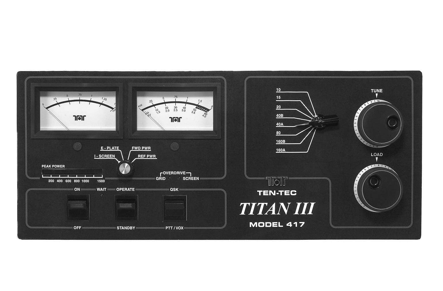
DJ768FTT417
Mar 16, 2003AMP - Amplifier
Equipment Class
AMP - Amplifier
DJ7-526
Apr 04, 20012-6 Meter Scanning RX/TX
Equipment Class
CXX - Communications Rcvr for use w/ licensed Tx and CBs