DJ7-588HF AMATEUR RADIO TRANSCEIVER
Ten Tec Inc
Click to zoom
Application Details
- Equipment Class
- CSR - Scanning Receiver
- Date of Grant
- Nov 15, 2006
- Application Purpose
- Original Equipment
- Date of Application
- Nov 15, 2006
- Equipment Note
- HF AMATEUR RADIO TRANSCEIVER
- Frequency Range
- 30.00000000 - 54.00000000
- Company
- Ten Tec Inc
- Country
- United States
Documents & Files
Document Text
Text extracted from the exhibit documents filed with the FCC. Open a document above to read the original.
Users Manual
Section 1 – YOUR NEW OMNI-VII Our aim in designing and producing OMNI- VII was to meet the demands of increasingly intense competition in DXing and contesting, while adding many non-performance related features that the active ham can also appreciate. OMNI-VII offers superb reception and transmission of CW, SSB, digital modes, FM, and AM on all 10 HF amateur bands and 50 MHz. UNPACKING OMNI-VII Examine OMNI-VII for signs of shipping damage. Should any damage be apparent, notify the delivering carrier immediately, stating the full extent of the damage. Retain all damaged cartons. Liability for shipping damage rests with the carrier. We recommend that you keep the carton and fillers in the event that storage, moving, or shipment becomes necessary. The hardware and accessories listed in Figure 1-1 come standard with your OMNI- VII. Make sure that you have not overlooked anything. ABOUT THIS MANUAL The OMNI-VII is a firmware updateable transceiver. Features and functions on the transceiver can change as time passes when new firmware revisions are issued via Ten-Tec’s www.rfsquared.com firmware download website. The latest version of the OMNI-VII manual is posted in .pdf format on the OMNI-VII section of the Ten-Tec website at www.tentec.com. Schematic diagrams are not included in this manual but are available for download from the www.rfsquared.com firmware website. This manual was written by Scott E. Robbins, W4PA. Qty Part # Description 1 #27074 Mini-ATC Blade Fuse, 25 Amp. 1 #35003 Phono Plug 1 #35363 8-pin Microphone Connector 1 #35165 2-pin Power Connector Shell 2 #41020 Female Power Pins 1 #35017 Phone Plug, 3- circuit 1 #38040 .050 Hex Wrench 1 #38088 .062 Hex Wrench 1 #38313 T10 Torx Wrench 1 #46172 Serial Cable 1 #46176 Accessory Cable. 5-pin DIN to phono female 1 #74020 Warranty Card 1 #74409 User’s Manual 1 #86095 DC Power Cord Figure 1-1 OMNI-VII Packing Kit CONNECTING A POWER SUPPLY The OMNI-VII transceiver requires a source of well-filtered and regulated DC voltage. The supply voltage can range from +12.8 to +15.0 Vdc but +13.8 Vdc is the optimum value. The voltage source must be capable of supplying 22 amperes continuous duty. We recommend using the included DC power cable (P/N 86095). We have also included spare connector pins (P/N 41020) and a spare 2 pin power connector shell (P/N 35165) for building your own cable. The power supply plug will attach in only one direction to the polarized two-pin DC connector on the OMNI-VII rear panel. Use no less than #14 gauge (#12 recommended) stranded wires for three-foot long connections to accommodate the required current demand during transmit. Use heavier gauge wire for longer power supply leads. NOTE: always enable the power source first and then the transceiver. If a generator or alternator supports the dc source, always turn off the transceiver before starting or 588 manual Initial release – October 2006 1 Part #74409 Printed in USA shutting off the dc source equipment. These recharging devices often generate large voltage spikes that can damage the transceiver. A WORD ABOUT GROUNDING A good ground system is essential for optimum operation of any HF transmitter. The best solution is to connect all the station equipment chassis together using a heavy gauge of flat ground braid. Use a short length of braid to connect to a ground rod. If you are not using a linear amplifier, a less ideal ground may suffice. A ground connection to a copper cold water pipe was often suitable, but that is now a violation of the National Electrical Code. Be aware that many modern water connections use plastic pipe, and are not suitable ground connections. Antenna type and its proximity to the station are also factors in choosing ground methods. With good resonant antennas located away from the station, the AC ground in your house wiring might be adequate. PHILOSOPHY OF DESIGN Ten-Tec’s goal with the OMNI-VII transceiver was to provide an HF transceiver that meets several disparate criteria. 1) Be easy for the average amateur to operate. 2) Have a feature set that experienced amateurs expect a top of the line piece of equipment to include. 3) Offer Amateur Radio’s first completely Ethernet controllable HF rig, with an eye to remote operation becoming more and more popular as time passes. 4) Include general coverage HF receive capability plus 50 MHz. The filtering system in the OMNI-VII uses what we refer to as “distributed” roofing filters. The definition of roofing filters varies; in Amateur Radio terms the term has come to mean a crystal or mechanical filter that allows for the preservation of available receiver performance for realistic on-the-air situations, as opposed to lab conditions when only two signals at a given spacing are present for test purposes. General coverage HF transceivers today are of an upconverting, VHF level first I-F, followed by two or three more conversion stages. This VHF I-F first stage is somewhat problematic due to physics to create an adequate mode-appropriate roofing filter. At the same time, some amateurs are reluctant to use a ham bands- only HF transceiver that may have a low frequency first I-F and be generally more suited to high performance applications than a general coverage HF rig. The question was how to combine a general coverage receiver with a mode-appropriate system of filtering appropriate for high-end Amateur Radio receiver performance. We refer to the roofing filters in the OMNI-VII as “distributed” because filters are spread across both the first and second I-F stages. The conversion stages in the OMNI-VII are 70 MHz first I-F, 455 kHz second I-F, 12 kHz (DSP) third I-F. Monolithic filters at 20 and 6 kHz are present at the first I-F stage. Selectable second I-F filters at bandwidths of 2.5 kHz, 500 Hz (optional) and 300 Hz (optional) can be cascaded with the first I-F monolithic filter at 6 kHz bandwidth. Bandwidth filtering is done in DSP at the third I-F and is controlled by the BW encoder on the tra…
Text truncated - open the document above for the full version.
Attestation Statements
November 6, 2006 Federal Communications Commission Authorization and Evaluation Division 7435 Oakland Mills Road Columbia, MD 21046 USA Re: FCC ID: DJ7-588 Subject: Attestation Letter Gentlemen: The scanner receiver equipment meets the requirements of the FCC Rules, 15.121(a). Compliance is achieved through the following methods: The scanner receiver in this equipment is incapable of tuning, or readily being altered, by the user to operate within the frequency bands allocated to the Domestic Public Cellular Telecommunications Service in Part 22. Blocking of the cellular frequencies is implementedin the firmware of the unit’s main control central processing unit (CPU). Thus coverage of 824– 849 MHz and 869– 894 MHz is not possible, since it is done in the microprocessor, and cannot be re-enabled by any user-accessible procedure, software or hardware, including diode, resistor, or jumper changes, nor by connection of any external device such as a personal computer, nor by installation of any “special” enabling semiconductor device. Sincerely, Mike Webber RF Engineer Ten-Tec, Inc. 1185 Dolly Parton Parkway Sevierville, TN 37862 Ph. (865)453-7172 ext. 230 Fax (865)428-4483 [email protected] www.tentec.com
External Photos
MODEL 588 Front View MODEL 588 Rear View MODEL 588 Top View MODEL 588 Bottom View
ID Label/Location Info
This view of the Model 588 shows the location of the warning label as required by FCC Part 15 Doc Section 15.121 (f). The label reads as follows and the sample is provided in the label sample file. WARNING: MODIFICATION OF THIS DEVICE TO RECEIVE RADIOTELEPHONE SERVICE SIGNALS IS PROHIBITED UNDER FCC RULES AND FEDERAL LAW. MODEL 588 SERIAL REM POD ACC 2 ACC 1 SPKR KEY SPARE SPARE TX EN TX OUT REAR PANEL MODEL 588 93757 10/31/06 PO# XXXXX DC OUT ETHERNET ANT 1 ANT 2 AUX RX FCC ID DJ7-588 This device complies with Part 15 of the FCC Rules. Operation is subject to the following two conditions: (1) this device may not cause harmful interference, and (2) this device must accept any interference received, including interference that may cause undesired operation. FUSE 25A DC IN + - .5 A MAX TEN-TEC, INC. SEVIERVILLE, TN MADE IN USA WWW.TENTEC.COM
Parts List/Tune Up Info
LEVELPART IDDESCRIPTIONDATEQTY/ASSY UOM 0588HF RADIO OMNI 706/10/20EA 138295L/F BERYLLIUM COPPER FING06/05/310.0625 EA 141039L/F LUG-LOCK,INT.TOOTH #405/04/191.0000 EA 142020BUMPER-RUBBER,3/4 DIA,3/805/04/192.0000 EA 142027BUSHING-.750 X 15/16 X 1/05/04/1912.0000 EA 142042BUSHING .5 X 23/32 X13/3605/04/192.0000 EA 146046WIRE-HOOKUP, #20 BLUE ST05/04/190.8750 FT 146178L/F 3 IN 30 CONDUCTOR05/04/191.0000 EA 146197DISPLAY CABLE FOR 58806/04/251.0000 EA 151001WASHER-LOCK,#6 INT TOOTH05/04/192.0000 EA 151002WASHER-LOCK,#4 INT TOOTH05/04/196.0000 EA 151007WASHER-FLAT,#10,7/16 OD,05/04/192.0000 EA 151034WASHER-LOCK,INTERNAL TOOT05/04/192.0000 EA 152023SPEAKER GASKET 3 IN ROUND05/04/191.0000 EA 154002NUT-4X40,.089THK,.250FLAT05/04/196.0000 EA 154005NUT-HEX,10X3205/04/191.0000 EA 154017NUT-WING,10X3205/04/191.0000 EA 160025SCREW-ST,6X32,1/4LG,PAN P05/04/194.0000 EA 160035SCREW-ST,10X32,3/4LG,PAN05/04/191.0000 EA 160069SCREW 440 X 3/8 PH PAN05/04/1919.0000 EA 160080SCREW - 440-3/16 UNDERCUT05/04/194.0000 EA 165003SCREW-SM,#6,3/8LG,PAN PHI05/04/192.0000 EA 165026SCREW-SM,#6,5/8LG,PAN PHP05/04/194.0000 EA 165028SCREW-SM, 4X24, 7/16 LG,05/04/1915.0000 EA 165056SCREW-TAPTITE 4-40 X 5/1605/04/1910.0000 EA 165057SCREW- #4 X 3/8 PANHEAD,05/04/194.0000 EA 165067SCREW-#10 X 32 X 1/205/04/194.0000 EA 177007TIE-CABLE,PANDUIT SSTIM05/04/195.0000 EA 181972SYNTHESIZER S/A MODEL 58805/04/211.0000 EA .221205L/F FB201209T-800Y-S SMD06/09/198.0000 EA .221222L/F INDUCTOR S/M 1.0 UH05/04/211.0000 EA .221226L/F INDUCTOR S/M 2.2UH05/04/211.0000 EA .221234L/F INDUCTOR S/M 10 UH05/04/2114.0000 EA .221297INDUCTOR-SMD COILCRAFT05/04/211.0000 EA .221325INDUCTOR 180NH SM080505/04/211.0000 EA .221326INDUCTOR 390NH SM080505/04/211.0000 EA .2213270805CS-820XJBB SMD05/04/217.0000 EA .221344VHF-TRI TRANSFORMER SMD05/04/212.0000 EA .221347220NH COILCRAFT 120606/09/223.0000 EA .22134839NH COILCRAFT 120606/09/221.0000 EA .221352L/F INDUCTOR-200 NH 080505/04/211.0000 EA .221376L/F VCO-2-3-4 OSC. COIL06/07/103.0000 EA .221377L/F VCO # 1 OSC. COIL06/07/101.0000 EA .223309L/F CAP-FXD,100MF,25V06/10/051.0000 EA .223452CAP-SMD 0805 1.5PF05/04/214.0000 EA .223454L/F CAP-SMD 0805 2.2 PF05/04/212.0000 EA .223456L/F CAP-SMD 0805 3.3 PF05/04/211.0000 EA .223457L/F CAP-SMD 0805 3.9 PF05/04/211.0000 EA .223458L/F CAP-SMD 0805 4.7 PF05/04/212.0000 EA .223460L/F CAP-SMD 0805 6.8 PF05/04/212.0000 EA .223461L/F CAP-SMD 0805 8.2 PF05/04/219.0000 EA .223462L/F CAP-SMD 0805 10 PF05/04/214.0000 EA .223464L/F CAP-SMD 0805 15 PF05/04/211.0000 EA .223465L/F CAP-SMD 0805 18 PF05/04/211.0000 EA .223466L/F CAP-SMD 0805 22 PF05/04/215.0000 EA .223467L/F CAP-SMD 0805 27 PF06/09/222.0000 EA .223468L/F CAP-SMD 0805 33 PF05/04/216.0000 EA .223469L/F CAP-SMD 0805 39 PF05/04/212.0000 EA .223472L/F CAP-SMD 0805 68 PF05/04/214.0000 EA .223474L/F CAP-SMD 0805 100 PF05/04/2115.0000 EA .223482L/F CAP-SMD 0805 470 PF05/04/214.0000 EA .223486LFCAP-SMD 0805 1000PF 50V05/04/2152.0000 EA .223487LFCAP-SMD 0805 0.01MF 50V05/04/214.0000 EA .223488LF CAP-SMD 0805 0.1MF 16V05/04/2152.0000 EA .223500L/F CAP-SMD 0805 3300PF06/09/063.0000 EA .223510L/F CAP-SMD 0805 .022MF05/04/211.0000 EA .223573CAP, TRIMMER 2.5-10 PF SM05/04/213.0000 EA .223575L/F CAP-SMD TANT 22UF 16V05/04/219.0000 EA .223577L/F CAP-SM-10UP TANT-16V05/04/2132.0000 EA .223640AVX CAP 1000 PF +/-5% X7R06/09/221.0000 EA .223642CHIP-CAP 27 PF SMD06/08/302.0000 EA .225095L/F LM340T5G05/04/211.0000 EA .225375LF TRANS-SMD MMBT3904LT1G05/04/214.0000 EA .225377L/F FET MMBFJ310LT1 SMD05/04/215.0000 EA .225380TRANS MMBR5179LT1 SMD05/04/212.0000 EA .225428L/F MC74HC04AD SMD05/04/211.0000 EA .225496L/F MC78L05ACDG 5V/VOLTAG05/04/211.0000 EA .225498MC78L08ACD 8 V VOLTAGE SM05/04/211.0000 EA .225522IC, PLL, 500HMZ SMD05/04/211.0000 EA .225568LM111-ADJ-REGULATOR SMD05/04/212.0000 EA .225569L/F IC-74HC238MS0I SMD05/04/211.0000 EA .225570IC-MC100EP140D SMD05/04/211.0000 EA .225571L/F IC-GALI51F MMIC AMP05/04/215.0000 EA .225573IC-AD9951 SMD05/04/211.0000 EA .225574IC-LT1964-LD-NEG-200M-REG05/04/211.0000 EA .225588RF SWITCH HMC194MS8 SMD05/04/214.0000 EA .225590L/F LM1117DTX-1.8V 800MA05/04/212.0000 EA .225591L/F LM1117DTX-3.3-ND SMD05/04/212.0000 EA .225592AD829AR SMD05/04/211.0000 EA .225593SANYO 2SK1740-4-TB-E SMD06/10/121.0000 EA .225616L/F MMIC AMP GALI-7406/08/301.0000 EA .228124L/F DIODE MMSD914T1G,SMD,05/04/214.0000 EA .228131DIODE, VARACTOR BB132 SMD05/04/219.0000 EA .228173L/F LED, GREEN 0805, SMD,06/09/221.0000 EA .230629L/F RES-SMD 0805 O OHM05/04/2115.0000 EA .230638L/F RES-SMD 0805 10 OHM05/04/214.0000 EA .230641L/F RES-SMD 0805 18 OHM05/04/212.0000 EA .230644L/F RES-SMD 0805 33 OHM05/04/211.0000 EA .230646L/F RES-SMD 0805 47 OHM05/04/218.0000 EA .230649L/F RES-SMD 0805 82 OHM05/04/212.0000 EA .230650L/F RES-SMD 0805 100 OHM05/04/2123.0000 EA .230652L/F RES-SMD 0805 150 OHM05/04/2110.0000 EA .230654L/F RES-SMD 0805 220 OHM05/04/216.0000 EA .230655L/F RES-SMD 0805 270 OHM05/04/215.0000 EA .230662L/F RES-SMD 0805 1.0K OHM05/04/215.0000 EA .230663L/F RES-SMD 0805 1.2K OHM05/04/212.0000 EA .230669L/F RES-SMD 0805 3.9K OHM05/04/212.0000 EA .230670L/F RES-SMD 0805 4.7K OHM05/04/211.0000 EA .230674L/F RES-SMD 0805 10K OHM05/04/217.0000 EA .230675L/F RES-SMD 0805 12K OHM05/04/211.0000 EA .230680L/F RES-SMD 0805 33K OHM06/09/221.0000 EA .230681L/F RES SMD 0805 39K OHM05/04/211.0000 EA .230682L/F RES-SMD 0805 47K OHM05/04/214.0000 EA .230688L/F RES-SMD 0805 150K OHM05/04/214.0000 EA .230690L/F RES-SMD 0805 220K OHM05/04/211.0000 EA .230694L/F RES-SMD 0805 470K OHM06/09/221.0000 EA .230698L/F RES-SMD 0805 1.0M OHM05/04/215.0000 EA .230738L/F RES-SMD-0805-120 OHM05/04/2112.0000 EA .230739L/F RES-SMD-0805-51 OHM05/04/214.0000 EA .230741RES-SMD-0805-12 OHM 5%05/04/216.0000 EA .230750L/F RM10J201CT 0805 20005/04/212.0000 EA .230751L/F POT 10K OHM 2MM SMD05/04/211.0000 EA .230756L/F RES-16 OHM 0805 1%06/04/211.0000 EA .230757L/F RES-36 OHM 0805 1%06/04/212.0000 EA .230805L/F RES 22 5% 0603 SMD06/10/031.0000 EA .235068L/F CONNECTOR-PC MT…
Text truncated - open the document above for the full version.
Test Report
Page 1 of 56 MEASUREMENT TECHNICAL REPORT FOR Ten-Tec, Inc. 1185 Dolly Parton Parkway Sevierville, Tennessee 37862 MODELS: 588 Report: G610199r1 r1 add ANSI Refernce Report Date: October 17, 2006 Date Test Sample Received: October 11, 2006 This report concerns: EMC (FCC Part 15) Testing of Amateur Radio Receiver Test report was prepared by and test performed at: GLOBAL TESTING LABORATORIES, LLC 3029 East Governor John Sevier Highway Knoxville, Tennessee 37914-6424 Written By October 17, 2006 Joe G. Clark Date Senior Mgr. Regulatory Affairs Reviewed By October 17, 2006 Roger Williams Date Senior Mgr. Engineering Authorized By October 17, 2006 Date Deborah Walker General Mgr Page 2 of 56 LIST OF EXHIBITS Report # G610199 1. Summary of Results 2. Engineering Statement 3. System Test Configuration 4. Radiated Emissions (FCC Part 15) 5. Conducted Emissions (FCC Part 15) 6. Receivers Ability to Reject Strong Cellular Signals (FCC Part 15) Page 3 of 56 SECTION 1 SUMMARY OF RESULTS Report Number G610199 The measurement uncertainty of this data (Report # G610199) is ±3 db. This report covers only the listed Model: 588,which indicates that the previously mentioned equipment MEETS,the requirements as set forth by the following standards for the listed Test: Test and Standard: Comments: Radiated Emissions (FCC Part 15) MEETS Conducted Emissions (FCC Part 15) MEETS Immunity to Cellular Phone Signals (FCC Part 15) MEETS Mass production of final instrument systems utilizing the exact electrical/ mechanical components, lead dress, and RF ground paths as tested by Global Testing Laboratories, LLC will not likely cause harmful interference to any radio communication, radio navigation or safety services. Any deviation in design from the system tested by our facility will require further verification of Compliance by Global Testing Laboratories, LLC. This test report is the confidential property of Ten-Tec, Inc.. Extracts from this test report shall not be reproduced except in full without our written approval. Senior Manager Regulatory Affairs Global Testing Laboratories, LLC Page 4 of 56 SECTION 2 ENGINEERING STATEMENT Report Number G610199 Engineering Statement All measurement data, in this report, was taken pursuant to the FCC Part 15, by Global Testing Laboratories, LLC (NVLAP Code: 200409-0), located in Knoxville, Tennessee. Although this data is taken under stringent laboratory conditions and to the best of our knowledge, represents accurate data, it must be recognized that emissions from this type of equipment may be greatly affected by the final installation of the equipment. Therefore, Global Testing Laboratories, LLC, while supporting the accuracy of the data in this report, takes no responsibility for use of equipment based on these tests. The manufacturer of this equipment must take full responsibility for any field problems, which may arise, and agrees that Global Testing Laboratories, LLC, in performing its functions in accordance with its objectives and purposes, does not assume or undertake to discharge any responsibility of the manufacturer to any other party or parties. Testing on the Ten-Tec, Inc. Model 588 was performed on October 11, 2006. The data contained within this technical report was compiled and approved by: Joe G. Clark Global Testing Laboratories, LLC 3029 East Governor John Sevier Highway Knoxville, Tennessee 37914-6424 Page 5 of 56 SECTION 3 SYSTEM TEST CONFIGURATION Report Number G610199 The Ten-Tec, Inc. Model 588was configured into a simulated installation. The specific setup for each test performed is described in each section Page 6 of 56 SECTION 4 RADIATED EMISSIONS Report Number G610199 PROCEDURE-RADIATED EMISSIONS FCC Part 15 (2006) Radiated Emissions measurements are investigated and taken pursuant to the procedures of ANSI C63.4 (2003). The EUT was placed on a wooden platform in a typical configuration .8m above metal turntable mounted level with the metal ground plane. A Biconical antenna was placed 10 meters away from the EUT on a 4-meter fiberglass mast. The receiving antenna was connected to the 50 ȍ input of the HP8566B spectrum analyzer. The EUT was powered by a 120VAC 60Hz, and was configured into its normal operational mode. The 30 MHZ to 40 MHZ band was observed on the spectrum analyzer while the EUT power and control leads were adjusted to maximize emissions. The remote turntable was rotated 360 degrees to find the maximum emissions. The peak frequencies for this band were recorded. This search for emissions continued from 40 MHZ up to 1 GHz. The receiving antennas were varied in height from 1 to 4 meters, for frequencies from 30MHZ to 1GHZ and the remote turntable was rotated 360 degrees to find the maximum emissions. This test was performed for all modes of operation. All significant emissions are reported on the attached data report. To verify that the E.M.I. emissions measured were generated by the E.U.T., the system power was interrupted at peak reading while observing the Spectrum Analyzer. Unless otherwise specified, all Radiated Emissions are recorded as "PEAK" spectrum analyzer readings. The Radiated Field Strength was calculated as follows: Maximum Emission Received (dB) + Antenna Factor (dB) + Cable Loss (dB) = Field Strength dBuv/Meter. Equipment Used During Testing: HP 8566B s/n: 6612 Spectrum Analyzer HP 85650A s/n: 1001 Quasi-Peak Adapter HP 85685A s/n: 0627 RF Pre-selector EMCO 3110 s/n: 1549 Biconical Antenna EMCO 3146 s/n: 3455 Log-Periodic Antenna Page 7 of 56 SUPPLEMENTAL DATA 6-METER BAND Report#: G610199 GLOBAL TESTING LABORATORIES, LLC 3029 GOV. JOHN SEVIER HWY. KNOXVILLE, TENNESSEE 37914 TEL:(865)523-9972 FAX:(865)637-7598 OPEN FIELD RADIATION MEASUREMENT FCC PART 15 CLASS "B" LIMITS REPORT #: G610199 MANUFACTURE: Ten-Tec MODEL # 588 DATE: 10/11/2006 NOTE: 6 meter DELTA REFERS TO THE dB DIFFERENCE BETWEEN THE HORIZONTAL OR VERTICAL READING AND THE dB LIMIT AT THAT FREQUENCY. THE FOLLOWING ARE PEAK READINGS WITH CABLE AND ANTENNA F…
Text truncated - open the document above for the full version.
Test Setup Photos
Page 18 of 56 Photograph: Radiated Emissions REPORT #G610199 Page 19 of 56 Photograph: Radiated Emissions REPORT #G610199 Page 43 of 56 Photograph: Conducted Emissions REPORT #G610199 Page 44 of 56 Photograph: Conducted Emissions REPORT #G610199 Page 45 of 56 Photograph: Conducted Emissions REPORT #G610199 Page 55 of 56 Photograph: Immunity REPORT #G610199 Page 56 of 56 Photograph: Immunity REPORT #G610199
Contact Information
Applicant
Jack Burchfield(President)
Test Firm
Global Testing Laboratory, LLCCaile Gonzalez
Technical Specifications
| # | Rule Parts | Frequency Range | Power Output |
|---|---|---|---|
| 1 | 15B | 30 MHz - 54 MHz | - |
Other Applications from Ten Tec Inc

DJ7-539
Nov 13, 2012HF AMATEUR RADIO TRANSCEIVER
Equipment Class
JBP - Part 15 Class B Computing Device Peripheral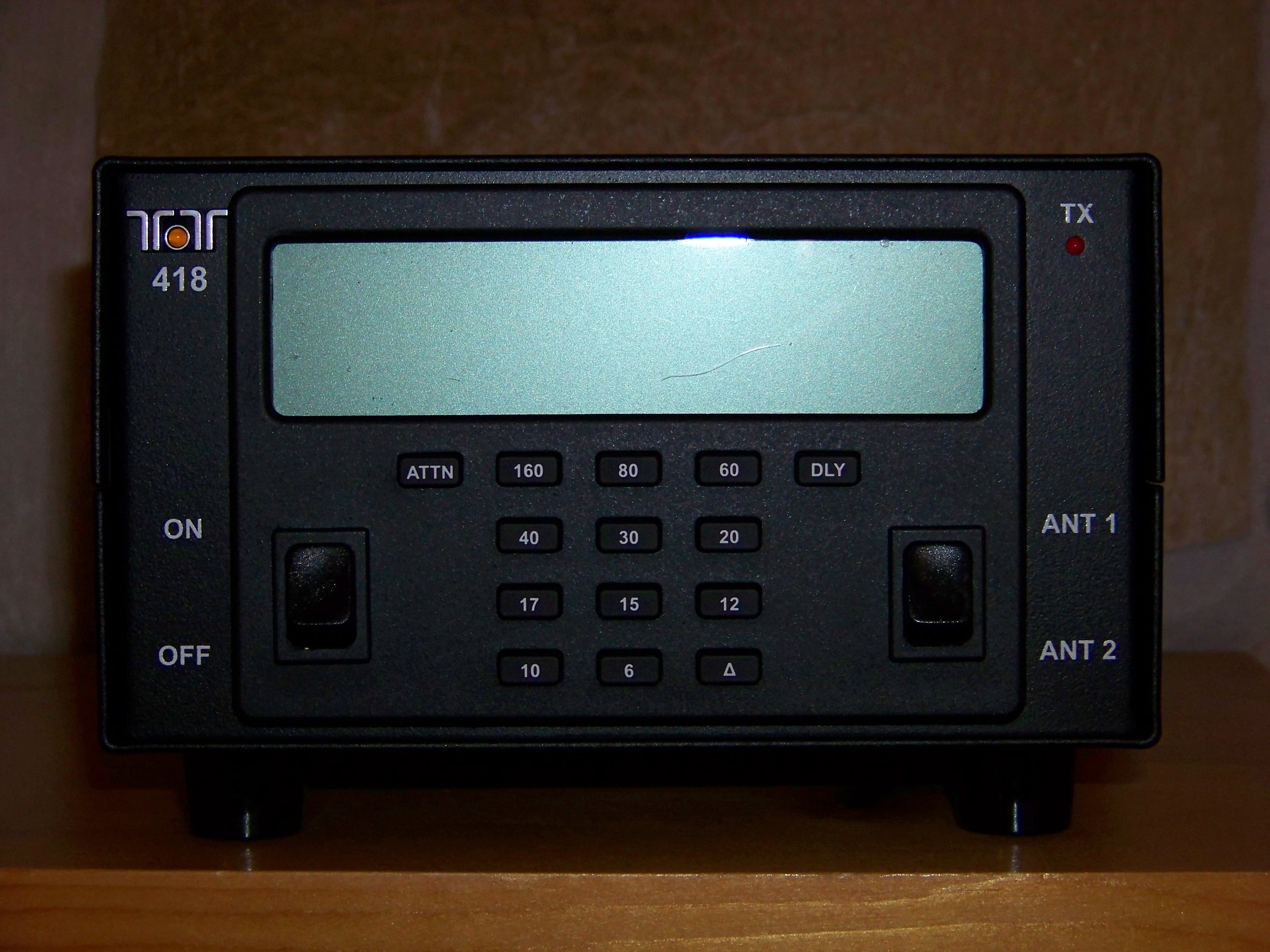
DJ7-418
Mar 01, 2012100W EXTERNAL RF AMPLIFIER
Equipment Class
AMP - Amplifier
DJ7-599
Oct 04, 2010SCANNING RECEIVER
Equipment Class
CSR - Scanning Receiver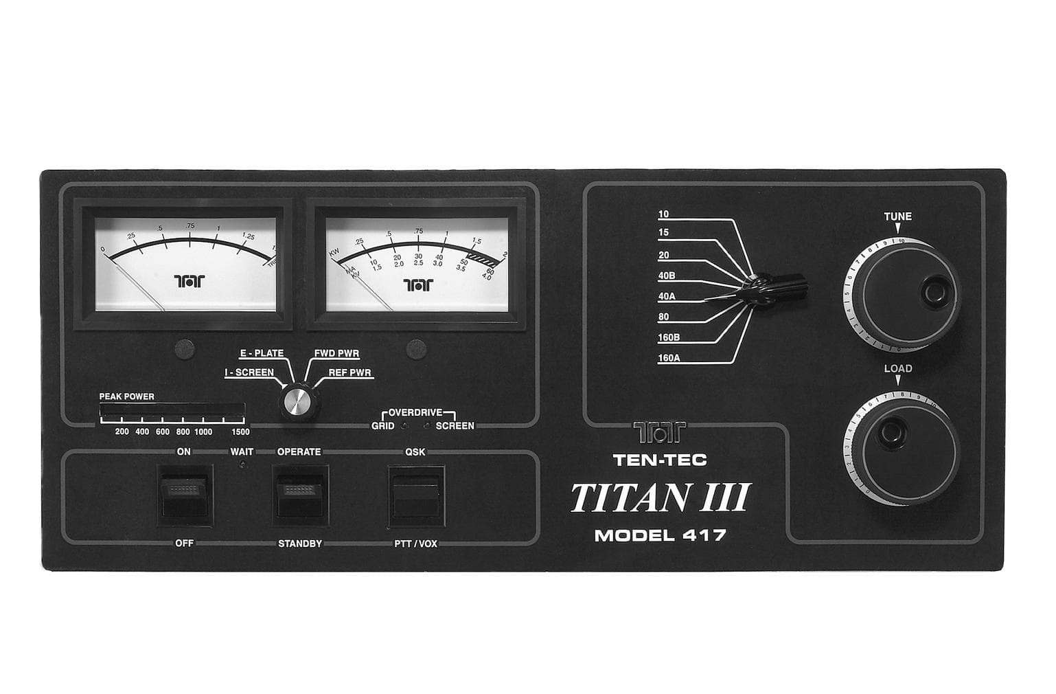
DJ768FTT417
Mar 16, 2003AMP - Amplifier
Equipment Class
AMP - Amplifier
DJ7-526
Apr 04, 20012-6 Meter Scanning RX/TX
Equipment Class
CXX - Communications Rcvr for use w/ licensed Tx and CBs