DJ7-5262-6 Meter Scanning RX/TX
Ten Tec Inc
Click to zoom
Application Details
- Equipment Class
- CXX - Communications Rcvr for use w/ licensed Tx and CBs
- Date of Grant
- Apr 04, 2001
- Application Purpose
- Original Equipment
- Date of Application
- Apr 04, 2001
- Equipment Note
- 2-6 Meter Scanning RX/TX
- Frequency Range
- 136.00000000 - 174.00000000
- Company
- Ten Tec Inc
- Country
- United States
Documents & Files
Document Text
Text extracted from the exhibit documents filed with the FCC. Open a document above to read the original.
Test Report
1 PHILIPS TESTING SERVICE Knoxville TN. TEST REPORT Customer: TEN-TEC Product: Amateur Transceiver, Model 526 Date: 30 March 2001 Purpose: Compliance Test of a new Scanning Receiver, per Federal Regulation 47 CFR 15.121 (b), “Scanning Receiver and Frequency Converters used with Scanning Receivers” Test Engineers: Bill Kaylor and Lyle Randall Test Conditions: Equipment: 1 each, TEN-TEC Amateur Transceiver, model 526 w/outboard Power Supply 2 each, Hewlett Packard RF Signal Generators, model 8640B 1 each, Sound Design Audio Distortion Analyzer, model 1700B 3 each, ANZAC Low-loss Impedance Transformers, model TP-75-4 1 each, Wide-band RF Signal Combining Network, 2 inputs/1 output Assorted cables, connectors, and between-series adaptive connectors Environment: Normal in-door temperature and humidity conditions were maintained. This test was not conducted inside of a RF shielded room or screen cage. Power Source: Non-preconditioned, unregulated 120 VAC power. Connections and configurations:(See referenced drawings and figures attached) All equipment w as allow ed a 30-minute w arm-up before testing w as begun. Test Procedure: The testing of the TEN-TEC model 526 transceiver's receiver was divided into two separate tests. The first test was to investigate the receiver’s ability to reject any response to a strong cellular signal that was presented at any of the receiver’s antenna inputs. To perform this test, the following conditions were established: (1) One of the Hewlett Packard RF Generators was connected directly to one of the transceivers two antenna inputs (Figure 1) (2) The transceivers “Mode” switch was set to select FM receiver operation within the band for the antenna the RF generator was connected to (3) The receiver “Volume” control was adjusted to mid-range and the “Squelch” control was adjusted for a constant noise in the speaker. (4) The HP RF Generator was set to provide a RF output on one of the selected Cellular Telephone frequencies with an output power level of –47 dBm. This signal was FM modulated with a 1000 Hz tone for a deviation of 3 kHz. With these conditions maintained, the transceiver’s receiver was slowly tuned from one limit to the other (50 to 54 MHz or 136 to 174 MHz). Any responses (demodulated audio at the speaker) that 2 contained a 1000 Hz tone modulation was presumed to be a response to the RF generator’s input signal. At the completion of the tuned sweep of one of the receivers bands, the RF generator signal was transferred to the other antenna input. The receiver “BAND” switch was depressed to change to the other operational band. A slow tuning of this second band was performed while listening for any audio responses in the speaker audio that contained a 1000 Hz modulated tone. When this second receiver tuned sweep was completed, the frequency of the RF generator was set to the next Cellular Band frequency and these two receiver tests were begun again. The transceiver receiver w as tested using six (6) separate Cellular Band frequencies and any responses w ere noted. TEST RESULTS, Test #1. Test # \\ Generator Freq. (MHz) \\ Receiver Band \\ Responses 1a824 MHz50 to 54 MHzNone observed 1b824 MHz136 to 174 MHz None observed 1c836.5 MHz50 to 54 MHzNone observed 1d836.5 MHz136 to 174 MHz None observed 1e849 MHz50 to 54 MHzNone observed 1f849 MHz136 to 174 MHz None observed 1g869 MHz50 to 54 MHzNone observed 1h869 MHz136 to 174 MHz None observed 1j881 MHz50 to 54 MHzNone observed 1k881 MHz136 to 174 MHz None observed 1m881 MHz50 to 54 MHzNone observed 1n881 MHz136 to 174 MHz None observed The second of the two tests on this receiver was conducted to examine it’s performance when two separate signals were presented to the receiver’s antenna input simultaneously, one in-band and the second, a strong Cellular Band signal. To perform this test, the following conditions were established: (1) Tw o HP RF Signal generators w ere connected to the RF input of the transceiver through a low-loss, wide band RF combining network. (Figure 2) (2) HP RF Signal generator #1 was the source of the “Undesired” signal. It supplied a Cellular Band signal at a –47 dBm, FM modulated with a 1000 Hz tone. HP RF Signal generator #2 supplied the “Desired” signal to the receiver. This was a frequency that was either at the low end, mid-range, or upper end of the selected transceiver receiver’s operating band. The generator output was set to provide a 30 uV signal, FM modulated with a 400 Hz tone. (3) The transceivers “Mode” switch was set to select FM receiver operation within the band for the antenna the combined RF generators was connected to. (4) The receiver “Volume” control was adjusted to mid-range and the “Squelch” control was adjusted for a constant noise in the speaker. With these conditions maintained, the transceiver’s receiver was slowly tuned from one limit to the other (50 to 54 MHz or 136 to 174 MHz). Any responses other than a clean 400 Hz modulated tone (demodulated audio at the speaker) was presumed to be a response to either the Undesired signal or a mix product of the Undesired and the Desired signals. At the completion of the tuned sweep of each of the receivers bands, the RF generator's signal was transferred to the other antenna input. The receiver “BAND” switch was depressed to change to the other operational band. The frequency of the Desired generator w as reset to the next appropriate test frequency w ithin the band being tested. Then, while listening for any audio responses other than a 400 Hz tone in the speaker output audio, another slow tuning of the receiver was performed. When this second receiver tuned sweep was completed, the frequency of the Undesired RF generator was set to the next Cellular 3 Band frequency and these two receiver bands were tested again. The transceiver receiver was tested using six (6) separate Cellular Band frequencies and any response other than a 400 Hz response is noted. TEST RESULTS, Test #2. Test # \\ Gen. Undesired \\ Gen. Des…
Text truncated - open the document above for the full version.
Contact Information
Applicant
Jack Burchfield(President)
Test Firm
Global Testing Laboratory, LLCCaile Gonzalez
Technical Specifications
| # | Rule Parts | Frequency Range | Power Output |
|---|---|---|---|
| 2 | 15B | 136 MHz - 174 MHz | - |
Other Applications from Ten Tec Inc

DJ7-539
Nov 13, 2012HF AMATEUR RADIO TRANSCEIVER
Equipment Class
JBP - Part 15 Class B Computing Device Peripheral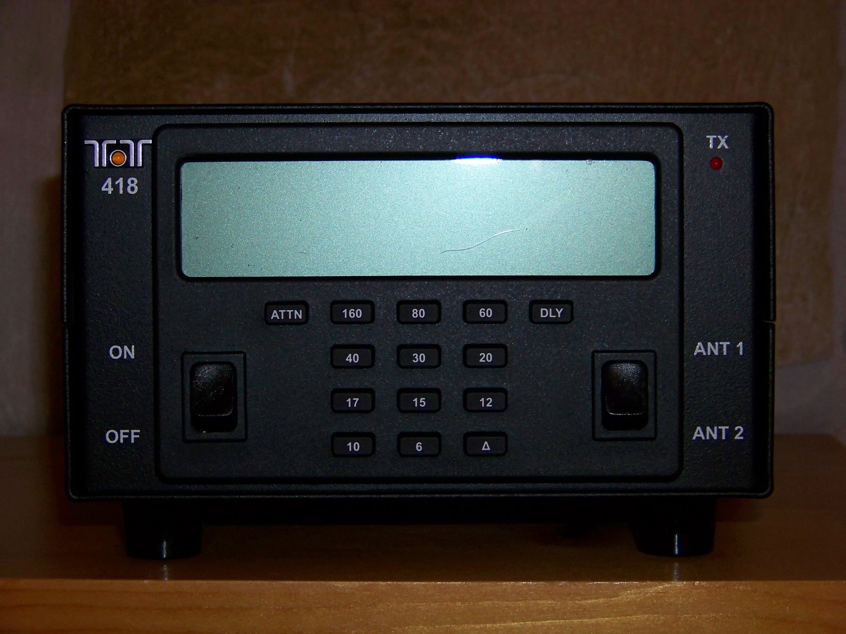
DJ7-418
Mar 01, 2012100W EXTERNAL RF AMPLIFIER
Equipment Class
AMP - Amplifier
DJ7-599
Oct 04, 2010SCANNING RECEIVER
Equipment Class
CSR - Scanning Receiver
DJ7-588
Nov 15, 2006HF AMATEUR RADIO TRANSCEIVER
Equipment Class
CSR - Scanning Receiver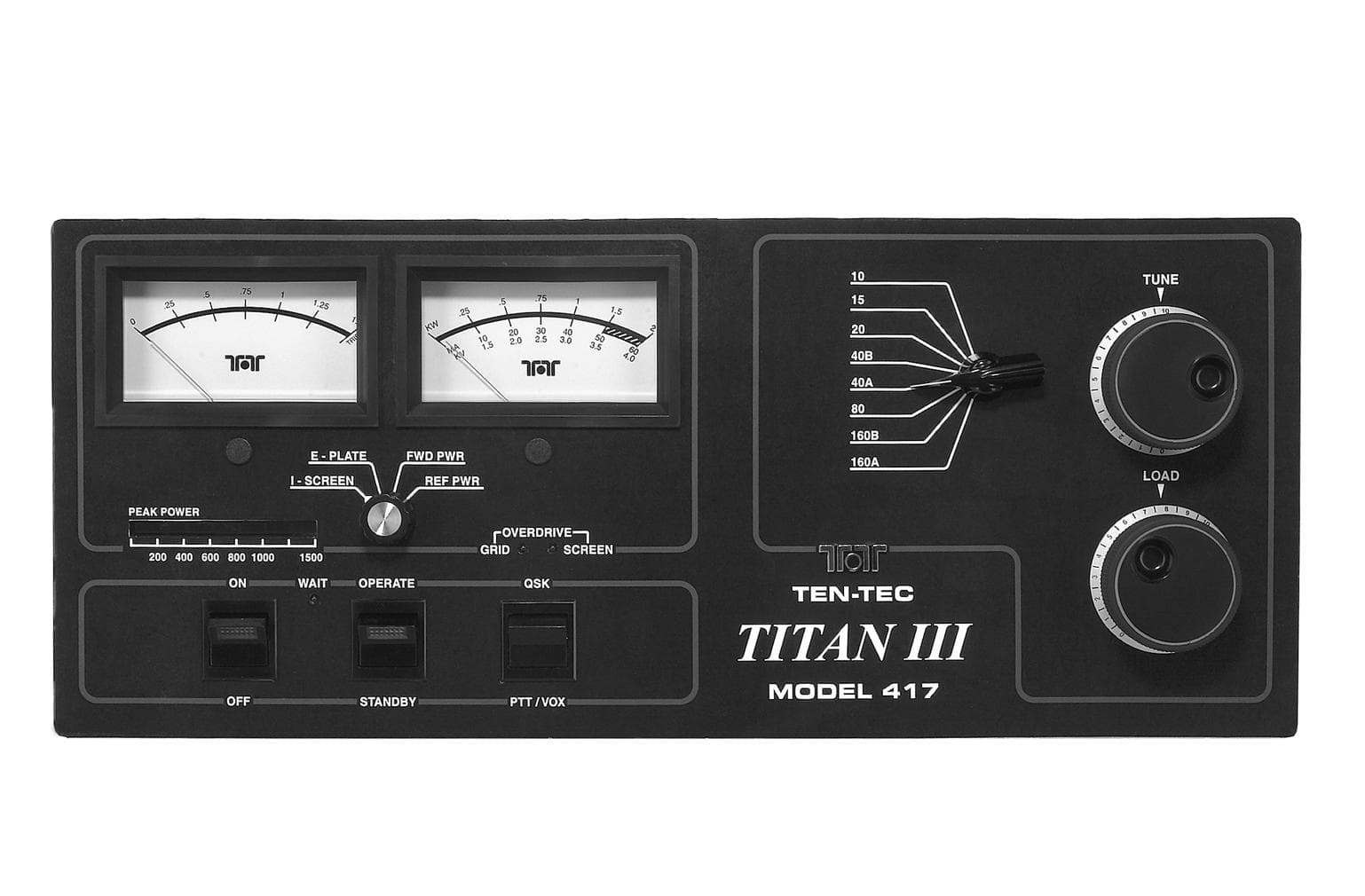
DJ768FTT417
Mar 16, 2003AMP - Amplifier
Equipment Class
AMP - Amplifier