DJ7-539HF AMATEUR RADIO TRANSCEIVER
Ten Tec Inc
Click to zoom
Application Details
- Equipment Class
- JBP - Part 15 Class B Computing Device Peripheral
- Date of Grant
- Nov 13, 2012
- Application Purpose
- Original Equipment
- Date of Application
- Nov 13, 2012
- Equipment Note
- HF AMATEUR RADIO TRANSCEIVER
- Company
- Ten Tec Inc
- Country
- United States
Documents & Files
Document Text
Text extracted from the exhibit documents filed with the FCC. Open a document above to read the original.
Users Manual
Table of Contents 1.Your new Argonaut VI 539..............................................................................................................................................3 1.1.Unpacking Argonaut VI Model 539..........................................................................................................................3 1.2.About this Manual......................................................................................................................................................3 1.3.Accessory package.....................................................................................................................................................3 1.4.Connection to Antenna & Power Supply...................................................................................................................4 1.5.A word about grounding............................................................................................................................................4 1.6.Philosophy of design..................................................................................................................................................5 2.Easy Operation Guide.......................................................................................................................................................6 2.1.Front Panel Indicators................................................................................................................................................6 TX/ALC LED.............................................................................................................................................................6 S-Meter / SWR Meter.................................................................................................................................................6 2.2.Front Panel Controls..................................................................................................................................................7 2.3.General Operations....................................................................................................................................................8 Power Switch (1)........................................................................................................................................................8 AF Gain Control (1)...................................................................................................................................................8 RF Gain Control (2)...................................................................................................................................................8 BW (3) Bandwidths..................................................................................................................................................9 PBT (4) Pass Band Tuning.......................................................................................................................................9 Band (7).....................................................................................................................................................................9 Split (8)......................................................................................................................................................................9 AGC (9)......................................................................................................................................................................9 A/B (10).....................................................................................................................................................................9 RIT (7).....................................................................................................................................................................10 POWER (7).............................................................................................................................................................10 Mode (10).................................................................................................................................................................10 Headphones (20 on rear panel)................................................................................................................................10 Tuning Steps and VFO LOCK (8)...........................................................................................................................10 PRE (8)....................................................................................................................................................................10 Recalling A Stored Memory (9)...............................................................................................................................11 Storing a Frequency to Memory (8)........................................................................................................................11 NR/NB (9) Noise Reduction/Noise Blanker..........................................................................................................12 2.4.SSB Mode Operation...............................................................................................................................................13 Monitor Level (3, 5, 7).............................................................................................................................................13 Speech Processing (3, 5, 8)......................................................................................................................................13 Auto Notch (9)..........................................................................................................................................................13 MIC Connector ..................................................................................................…
Text truncated - open the document above for the full version.
Block Diagram
10M 15M 160M ANT FWDREV LOW PASS / PA AGC LO1 10.8-39 MHz LO2 9.024 LL TX FIL TX AGC RX IF CLK, DAT, ENA MISO/MOSI FRONT PANEL/CPU LCD DISPLAY LCD DRIVER KEYPAD ENCODER EEPROM PWR ON/OFF 13.8V MIC MIC AMP MIC AUDIO REC AUDIO SPEAKER AMP SPU CODEDSP CLK, DAT, ENA TO SWITCHES PRESELECTOR R T MODEL 539 LINE IN/OUT ~22.5 kHz TX IF SYNTHESIZER REAR PANEL POWER REGULATOR 7.5A DC OUT PPTC 500 MA USB R T ROOFING FILTERS (9.0015 MHz) TX/RX F1 F2 F3 VGA R T R L I R T DDS R L I SWR BRIDGE TCXO ÷4 9MHz IF Output BACKLIGHT PIC 5V POT BOARD AF/RF BW/PBT POT A/D 10M 15M 160M R T
External Photos
FRONT VIEW REAR VIEW
External Photos
TOP SIDE VIEW BOTTOM SIDE VIEW
External Photos
LEFT SIDE VIEW RIGHT SIDE VIEW
ID Label/Location Info
This document providesa sample FCC ID label with compliance statement per Part 15 Section 19 (a) (3). The labelwill be permanently affixed to the rear panel of the radio with a permanent adhesive (see the label location file for the exact locations). FCC ID DJ7-53 9 This device complies with Part 15 of the FCC Rules. Operation is subject to the following two conditions: (1) this device may not cause harmful interference, and (2) this device must accept any interference received, including interference that may cause undesired operation.
ID Label/Location Info
This view of the Model 539 Rear Panel shows the location of the FCC ID label with compliance statement as required by Section 15.19 (a) (3). A sample of the label is provided in the label sample file.
Internal Photos
TOP VIEW BOTTOM VIEW
Internal Photos
TOP VIEW (W/O FILTER COVER)
Internal Photos
LEFT SIDE VIEW RIGHT SIDE VIEW
Internal Photos
SIGNAL PROCESSING UNIT TOP SIGNAL PROCESSING UNIT BOTTOM
Internal Photos
MOTHERBOARD TOP MOTHERBOARD BOTTOM
Internal Photos
DISPLAY BOARD TOP DISPLAY BOARD BOTTOM
Internal Photos
POT BOARD TOP POT BOARD BOTTOM
Internal Photos
LO BOARD TOP LO BOARD BOTTOM
Internal Photos
PRESELECTOR BOARD TOP PRESELECTOR BOARD BOTTOM
Internal Photos
POWER SUPPLY UNIT TOP POWER SUPPLY UNIT BOTTOM
Internal Photos
TX/RX BOARD WITH FILTER COVER TOP TX/RX BOARD WITHOUT FILTER COVER BOTTOM
Internal Photos
TX/RX BOARD WITHOUT FILTERS TOP TX/RX BOARD BOTTOM
Internal Photos
2800 Hz FILTER BOARD TOP 2800 Hz FILTER BOARD BOTTOM 700 Hz FILTER BOARD TOP 700 Hz FILTER BOARD BOTTOM
Internal Photos
10 WATT PA LOWPASS FILTER BOARD TOP 10 WATT PA LOWPASS FILTER BOARD BOTTOM
Internal Photos
REGULATOR BOARD TOP REGULATOR BOARD BOTTOM
Test Report
Page 1 of 1 6 MEASUREMENT TECHNICAL REPORT FOR Ten-Tec, Inc 1185 Dolly Parton Parkway Sevierville, TN 37862 M O D E L : 5 3 9 ( F C C I D : D J 7 - 5 3 9 ) A D D I T I O N A L M O D E L S : N o n e R E P O R T N U M B E R : G 1 2 1 1 1 3 2 R e p o r t D a t e : N o v e m b e r 6 , 2 0 1 2 Da t e T e s t S a m p l e Re c e i v e d : No v e m b e r 1 , 2 0 1 2 T h i s r e p o r t c o n c e r n s : ANS I C6 3 . 4 ( 2 0 0 9 ) wi t h F C C M e t h o d 4 7 C F R P a r t 1 5 , S u b p a r t B T e s t r e p o r t w a s p r e p a r e d b y a n d t e s t p e r f o r m e d a t : G L O B A L T E S T I N G L A B O RAT O RI E S , L L C 3 0 2 9 E a s t G o v e r n o r J o h n S e v i e r H i g h w a y K n o x v i l l e , T e n n e s s e e 3 7 9 1 4 - 6 4 2 4 Tested By November 5, 2012 Ben Gervais Date EMC technician Written By November 6, 2012 Cailé Gonzalez Date Vice President of Operations Approved By November 7, 2012 Deborah Walker Date CEO/President Page 2 of 1 6 LIST OF EXHIBITS REPORT # G1211132 1.Summary of Results 2.Engineering Statement 3.System Test Configuration 4.Conducted Emissions (FCC Part 15) 5.Radiated Emissions (FCC Part 15) 6.Copy NVLAP Certificate Page 3 of 1 6 SECTION 1 SUMMARY OF RESULTS REPORT # G1211132 This Test Report in no way constitutes or implies product certification, approval, or endorsement by NIST or any Government Agency and may not be used to imply such endorsement. The equipment used in this test provided a Test Uncertainty Ratio better than 4:1. Uncertainties are expressed at approximately 95% confidence level (k=2). This report covers only the listed Model: 539, which indicates that the previously mentioned equipment MEETS the requirements as set forth by the following standards: Conducted Emissions (FCC Part 15) Radiated Emissions (FCC Part 15) Mass production of final instrument systems utilizing the exact electrical/ mechanical components, lead dress, and RF ground paths as tested by Global Testing Laboratories, LLC will not likely cause harmful interference to any radio communication, radio navigation or safety services. Any deviation in design from the system tested by our facility will require further verification of Compliance by Global Testing Laboratories, LLC. This test report is the confidential property of Ten Tec. Extracts from this test report shall not be reproduced except in full without our written approval. Cailé Gonzalez Global Testing Laboratories, LLC Page 4 of 1 6 SECTION 2 ENGINEERING STATEMENT REPORT # G1211132 Engineering Statement All measurement data on the attached reports was taken pursuant to ANSI C63.4 by Global Testing Laboratories, LLC located in Knoxville, Tennessee. Although this data is taken under stringent laboratory conditions and to the best of our knowledge, represents accurate data, it must be recognized that emissions from this type of equipment may be greatly affected by the final installation of the equipment. Therefore, Global Testing Laboratories, LLC, while supporting the accuracy of the data in this report, takes no responsibility for use of equipment based on these tests. The manufacturer of this equipment must take full responsibility for any field problems, which may arise, and agrees that Global Testing Laboratories, LLC, in performing its functions in accordance with its objectives and purposes, does not assume or undertake to discharge any responsibility of the manufacturer to any other party or parties. The testing on the Ten Tec Model: 539 was performed on November 5, 2012. The data contained within this technical report was compiled and approved by: Cailé Gonzalez Global Testing Laboratories, LLC 3029 East Governor John Sevier Highway Knoxville, Tennessee 37914-6424 Page 5 of 1 6 SECTION 3 SYSTEM TEST CONFIGURATION REPORT # G1211132 The Ten Tec Model: 539 was configured into a simulated installation. The specific setup for each test performed is described in the following Sections. 539 (EUT) Hand Mic. RF Load (Support Equipment) Astron Power Supply (Support Equipment) USB Cable CW Key (Support Equipment) Head Phones (Support Equipment) Acc. Cable 120VAC 60Hz Page 6 of 1 6 SECTION 4 CONDUCTED EMISSIONS REPORT # G1211132 TEST PROCEDURE: ANSI C63.4 (2009) with FCC Method 47 CFR Part 15, Subpart B ACRONYMS: (E.M.I.) Electromagnetic Interference (E.U.T.) Equipment Under Test (L.I.S.N.) Line Impedance Stabilization Network CONDUCTED EMISSIONS: The (2) 50 ohm/50 micro-Henry LISN's were placed next to the EUT. For each test required, the AC power leads were connected to two (2) 50 ohm/50 micro-Henry L.I.S.N.s as described in section 9 Method of measurement of terminal interference voltage of CISPR 22/EN 55022. The system was energized and placed into its normal operating mode. The 50-ohm output of the L.I.S.N. was connected to the R&S ESCI Spectrum Analyzer. The EUT was observed from 150 kHz to 30 MHz to identify the frequency of the emission that had the highest amplitude relative to the limit. For each mode of operation and for each current carrying conductor, cable and/or wire manipulation was performed while observing the Spectrum Analyzer. For this series of tests the emission that had the highest amplitude relative to the limit was recorded. The EUT was powered by 120 VAC 60 Hz. Based on the preliminary tests, the EUT and the cable and/or wire configuration and mode of operation which produced the highest emission relative to the limit was selected for the final AC power line conducted emissions test. The final test on all current carrying conductors of the power cords that comprise the EUT was performed without variation of the configuration determined during the preliminary tests. The X-Y plots of EMI generated by the E.U.T. were taken. Calibration: Equipment Used During Testing: Cal. Date: Cal. Due: 02/22/12 02/22/13 R&S ESCI s/n: 100389 Spectrum Analyzer (1009) 11/30/11 11/30/12 Fisher 50 /50μH s/n: 9705 LISN (2001) 11/30/11 11/30/12 Fisher 50 /50μH s/n: 9706 LISN (2002) Software Rohde & Schwarz EMC32 V…
Text truncated - open the document above for the full version.
Test Setup Photos
Page 1 of 3 Photograph: Conducted Emissions Report # G1211132 Page 2 o f 3 Photograph: Radiated Emissions Report # G1211132 Page 3 o f 3 Photograph: Radiated Emissions Report # G1211132
Contact Information
Applicant
Jack Burchfield(President)
Test Firm
Global Testing Laboratory, LLCCaile Gonzalez
Technical Specifications
| # | Rule Parts | Frequency Range | Power Output |
|---|---|---|---|
| 1 | 15B | - | - |
Other Applications from Ten Tec Inc
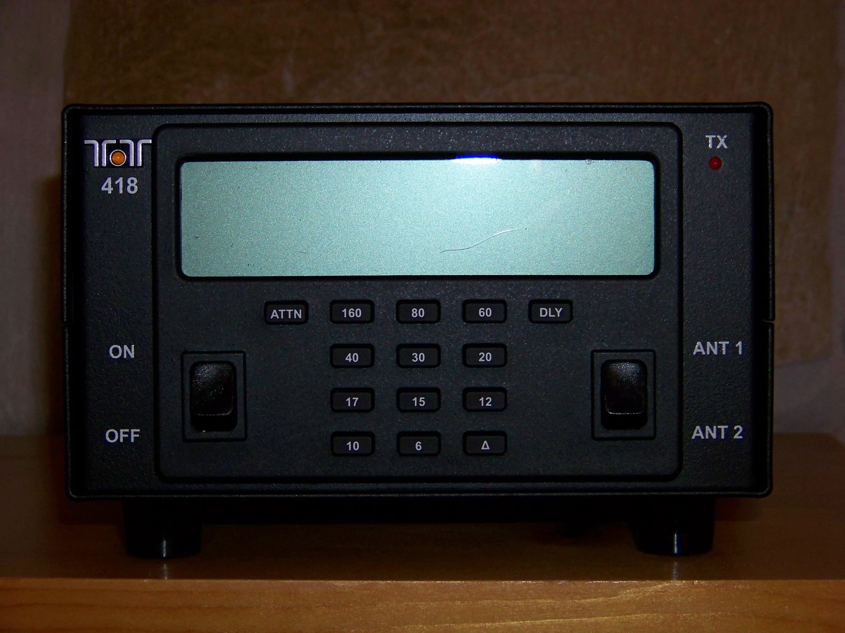
DJ7-418
Mar 01, 2012100W EXTERNAL RF AMPLIFIER
Equipment Class
AMP - Amplifier
DJ7-599
Oct 04, 2010SCANNING RECEIVER
Equipment Class
CSR - Scanning Receiver
DJ7-588
Nov 15, 2006HF AMATEUR RADIO TRANSCEIVER
Equipment Class
CSR - Scanning Receiver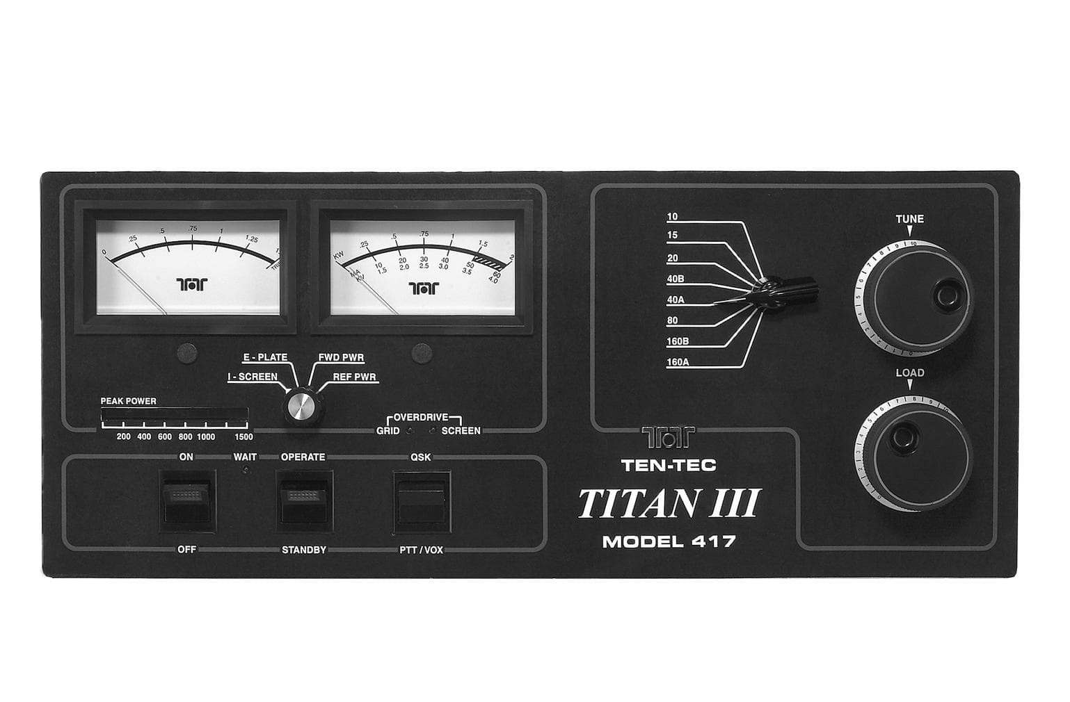
DJ768FTT417
Mar 16, 2003AMP - Amplifier
Equipment Class
AMP - Amplifier
DJ7-526
Apr 04, 20012-6 Meter Scanning RX/TX
Equipment Class
CXX - Communications Rcvr for use w/ licensed Tx and CBs