DWNDECOFLEX2Decoflex RTS In-Wall Mount 1810830
Somfy Systems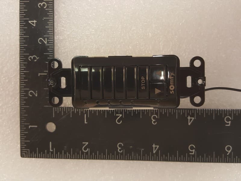
Click to zoom
Application Details
- Equipment Class
- DSC - Part 15 Security/Remote Control Transmitter
- Date of Grant
- Feb 25, 2026
- Application Purpose
- Original Equipment
- Equipment Note
- Decoflex RTS In-Wall Mount 1810830
- Frequency Range
- 433.42000000 - 433.42000000
- Company
- Somfy Systems
- Country
- United States
Documents & Files
Document Text
Text extracted from the exhibit documents filed with the FCC. Open a document above to read the original.
Users Manual
DecoFlex Keypad Instructions DECOFLEX WIREFREE™ RTS (Ref: 1810813 +others) DECOFLEX™ DIGITAL WALL SWITCHES SDN (Ref: 1811253 +others) DECOFLEX™ DIGITAL WALL SWITCHES SDN GROUP CONTROL (Ref: 1811749, 1811750) DECOFLEX™ DIGITAL WALL SWITCHES ANIMEO® IP (Ref: 1811289 +others) DECOFLEX DRY CONTACT KEYPAD for IGC 4n1 Motor Controller (Ref: 1811402) ASSEMBLY ASSEMBLE MULTIPLE BUTTON SWITCHES Begin with a standard (assembled) 1 or 5 control button DecoFlex switch. Using a small flat blade screw driver, carefully separate the SWITCH BASE ASSEMBLY from the FACEPLATE (as shown in figure 1). Add or remove CONTROL BUTTONS (as required) from the SWITCH BASE ASSEMBLY (as shown in figure 2). Be certain the SWITCH BASE ASSEMBLY remains intact. Attach new multiple button face plate (as shown in figure 3 & 4). 1 2 3 Applies to the following keypads: Figure 1. Figure 3. Figure 2. Figure 4. 5 Channel DecoFlex Wall Switch (Exploded view) Removable Channel Buttons Switch Base Assembly Wall Plate 8 Button Faceplate REPLACE STANDARD CONTROL BUTTONS Using a small flat blade screw driver, carefully separate the SWITCH BASE ASSEMBLY from the FACEPLATE (as shown in figure 1). Replace standard (blank) or temporarily labeled CONTROL BUTTON(s) with new engraved CONTROL BUTTON(s). Attach new CONTROL BUTTON FACE PLATE (as shown in figure 3 & 4). 1 2 3 5 Button Switch Assembly 6 Button Switch Assembly 7 Button Switch Assembly Battery Replacement: (RTS only) The DecoFlex WireFree™ RTS switch is designed to provide years of maintenance-free performance. Should the battery become discharged, the LED indicator lights will no longer function when the channel button is selected or an up, stop or down command is activated. As a result, the radio signal will be reduced or not communicated to the RTS receiver or motor. The battery can be easily replaced by exposing the SWITCH BASE ASSEMBLY board of the DecoFlex WireFree™ switch. Simply slide the battery out of its holder and replace with a new 3V Lithium battery (type 2450) maintaining the correct polarity. NOTE: Batteries should be disposed of properly according to local regulations. RTS Assembly/Installation/Operating Instructions SDN Cable Pinout: (RJ45 connector) ANSI/TIA/EIA 568-B Standard Keypad RJ45 Pinout: SDN, animeo IP and Dry Contact CAT-5e or higher TIA-568B standard with RJ-45 Pin #Color SDN & animeo IP Function Dry Contact Function 1Orange WhiteSDN RS485 ( + )IP1 2OrangeSDN RS485 ( - )IP2 3Green WhiteReservedIP3 4BluePower 24v DC ( + )12V+ 5Blue WhitePower 24v DC ( - )N/A 6GreenReservedDown 7Brown WhiteSDN RS485 GroundUp 8BrownSDN RS485 GroundGround KEYPAD PROGRAMMING Download and install Programming Guides and Software from this link. https://www.somfypro.com/services-support RTS: Follow our RTS Pocket Programming Guide to setup DecoFlex RTS keypads Dry Contact: Arrange switch for control in IGC 4n1 Motor Controller *Before installing keypads all motors must be wired to the controller, have limits set and be working properly. SDN: The DecoFlex Digital Keypads for SDN have programmable buttons which can be configured to control any motor or group using the SDN Keypad Programming Guide and SDN Keypad Configuration Software. Once a keypad is fully configured, all of the settings can be exported to a file for backup. animeo® IP: Keypads are configured within the animeo® IP commissioning software after installation on the SDN bus. Use animeo® IP Visual Configuration software. POWERING DECOFLEX KEYPADS DecoFlex Keypad P-0035 INSTALLATION © Copyright 1/2019 SOMFY SYSTEMS, INC. SAVE THESE INSTRUCTIONS FOR FUTURE REFERENCE Included is a special SOMFY low voltage device mounting bracket which attaches to drywall and eliminates the need for an electrical box. The bracket can be used in two mounting type configurations: The bracket is specifically designed for mounting the DecoFlex range wall switches to an adjacent (pre-existing) Decora-style light switch (see below).This unique mounting bracket allows the necessary spacing for 2 adjacent switches and a new “Double Gang” (2 Gang) wall plate to be installed (see photo 8) resulting in an aesthetically pleasing professional installation. NOTE: When following configuration 1, the mounting bracket is not designed to be used inconjunction with “old-work” or retrofit electrical boxes. (Please check local codes to determine if an electrical box is required for your installation.) For increased radio performance, Somfy recommends the use of non-metallic electrical enclosures. The bracket can also be used for individual or “stand-alone” (1 switch) mounting configurations. 1 2 Tools required for installation: Screw drivers (phillips and bladed), dry-wall saw, wall stud sensor, non-marring tape and pencil 1 Locate an existing light switch and remove wall plate exposing electrical box. Somfy recommends shutting off power to the exposed electrical box prior to installation. NOTE: If not installing keypad with an existing switch, skip to step 2. 2 Using a stud sensor, locate the stud nearest to exposed electrical box. Then mark (for reference) with removable tape or pencil. 3 Place the flat side of mounting bracket (included) against the wall and align the thin side over the outside edge of the existing electrical box (opposite the stud side). Center the bracket to align the mounting screw height with existing switch, then trace the inside shape of the bracket on wall using a pencil or thin marker. Using a dry-wall saw (or similar) begin to cut the drywall along the traced outline. Do not cut hole larger than outline as this may result in a loose fitting bracket. *For greater accuracy please refer to the recommended hole dimensions on reverse page. 4 5 Insert bracket (as shown) into hole, keeping the thin side closest to the edge of the existing switch box. 6 Carefully bend bracket tabs 90 degrees behind the dry-wall to ensure a tight secure fit. 7 Position the DecoFlex switch into mounting bracket aligning the screw holes. Secure switch to…
Text truncated - open the document above for the full version.
Attestation Statements
Somfy Systems, Inc., 121 Herrod Blvd., Dayton, NJ 08810 CFR 47 §2.911 (d)(7) Agent Designation Attestation Date: 06/18/2025 FCC ID: DWNDECOFLEX2 To: Federal Communications Commission 7435 Oakland Mills Road Columbia, MD 21046 USA Somfy Systems, Inc. (“the applicant”) as required by section 2.911(d)(7), will also serve as the agent for service of process for the above referenced FCC ID. The applicant acknowledges that they will maintain an agent for no less than one year after the grantee has terminated all marketing and importation or the conclusion of any Commission-related proceeding involving the equipment. The applicant further acknowledges their responsibility to inform the FCC whenever the agent’s information changes. Contact Person: Jim Hellander Company Name: Somfy Systems, Inc. (FRN# 0006579940) Company US Address: 121 Herrod Blvd., Dayton, NJ 08810 Email: [email protected] Sincerely yours, Jim Hellander
Attestation Statements
Rev 1/26/2023 Federal Communications Commission Authorization and Evaluation Division 7435 Oakland Mills Road Columbia, MD 21046 USA Date: 07-10-2025 Ref: Attestation Statements Part 2.911(d)(5)(i) Filing FCC ID: DWNDECOFLEX2 Somfy Systems, Inc. (“the applicant”) certifies that the equipment for which authorization is sought is not “covered” equipment prohibited from receiving an equipment authorization pursuant to section 2.903 of the FCC rules. Somfy Systems, Inc. (“the applicant”) certifies that the equipment for which authorization is sought does not include cybersecurity or anti-virus software produced or provided by Kaspersky Lab, Inc. or any of its successors and assignees, including equipment with integrated Kaspersky Lab, Inc. (or any of its successors and assignees) cybersecurity or anti-virus software pursuant to DA-24-886 and KDB 986446 D01 Covered Equipment Guidance section B(2a). Device is inherently compliant based on hardware limitations or software controls. or A Software Bill of Materials (SBOM) is provided to the TCB for review, and The end-user or third parties cannot install additional software on this device. Sincerely, Jim Hellander Rev 1/26/2023 Federal Communications Commission Authorization and Evaluation Division 7435 Oakland Mills Road Columbia, MD 21046 USA Date: 07-10-2025 Ref: Attestation Statements Part 2.911(d)(5)(ii) Filing FCC ID: DWNDECOFLEX2 Somfy Systems, Inc. (“the applicant”) certifies that, as of the date of the filing of the application, the applicant is not identified on the Covered List (as a specifically named entity or any of its subsidiaries or affiliates) as an entity producing “covered” equipment. Sincerely, Jim Hellander
Cover Letter(s)
Date: September 10, 2025 Ref: Application for FCC & ISED Certification on Somfy Tx under FCC ID: DWNDECOFLEX2 & IC:12049A-DECOFLEX2 Ctrl#: 0048-250910-01 From: Wei Li, Advanced Compliance Laboratory To Whom It May Concern: Dear Sir/ Madam, We, Advanced Compliance Laboratory, as EMC testing lab and agent, would like to represent the applicant, Somfy Systems to apply for your approval on product authorization for new certification under FCC ID: DWNDECOFLEX2 & IC:12049A-DECOFLEX2. The investigation for the EMC performance of the EUT(s), DECOFLEX RTS In-Wall Mount, Model# 1810830, performed in May, 2025 on behalf of the applicant. It was found that EUTs comply with the requirements of FCC Part 15.231(a) & RSS-210, RSS-Gen. The system was configured as the typical condition during the test. Enclosed please find the test data/report with application forms. The testing facility used to collect the emission data is located at Hillsborough, New Jersey, USA. This site is accepted by FCC to perform measurements under Part 15 or 18 (MRA designation No. US3288) and also designated by ISED with CAB ID# US0100 ( test site # IC 3130A). The ANAB Lab code for accreditation of FCC EMC Test Method is: AT-3288. Should you need more information, please contact me at (908) 392-3378 or email me to [email protected]. Your attention is highly appreciated. Sincerely, Wei Li Manager Advanced Compliance Laboratory, Inc. 210 Cougar Court Hillsborough, NJ 08844 Tel: (908) 927 9288 Fax: (908) 927 0728 Advanced Compliance Lab
Cover Letter(s)
Somfy Systems, Inc. 121 Herrod Blvd., Dayton, NJ 08810 July 10, 2025 To Whom it may Concern: I, the undersigned, hereby authorize, Wei Li, Advanced Compliance Lab, to act on behalf of Somfy Systems, Inc. in all matters to the current FCC and ISED applications for authorization, including signing of all documents relating to these matters. Sincerely, Jim Hellander Somfy Systems, Inc. FRN# 0006579940 [email protected]
Cover Letter(s)
7/ 10/25 FCC ID: DWNDECOFLEX2 IC ID: 12049A-DECOFLEX2 FCC and IC Confidentiality Request In accordance with 0.459 & 0.457 of CFR 47, please, accept this letter as an official request to have the schematics, block diagram, operational description of the EUT treated as confidential. The information contained within is a result of extensive investment and development effort by Somfy Systems, Inc. and its disclosure will compromise Somfy's Intellectual Property and competitive edge. We thus ask the FCC and IC NOT to publish the information mentioned above, in order to protect Somfy's Intellectual Property. Regards, Somfy Systems, Inc. Jim Hellander Electronics Engineer
External Photos
Product name: Decoflex RTS In-Wall Mount Model No: 1810830 FCC ID: DWNDECOFLEX2 IC: 12049A-DECOFLEX2 ______________________________________________________________________________________________ 21 7. PHOTOS OF TESTED EUT The following photos show the inside details of the EUT. Figure 7.1 Top/Front View (Dimension) Figure 7.2 Bottom/ Rear Label View Product name: Decoflex RTS In-Wall Mount Model No: 1810830 FCC ID: DWNDECOFLEX2 IC: 12049A-DECOFLEX2 ______________________________________________________________________________________________ 22 Figure 7.3 EUT Front View Figure 7.4 EUT Rear View Product name: Decoflex RTS In-Wall Mount Model No: 1810830 FCC ID: DWNDECOFLEX2 IC: 12049A-DECOFLEX2 ______________________________________________________________________________________________ 23 Figure 7.5 EUT Left View Figure 7.6 EUT Right View
ID Label/Location Info
Product name: Decoflex RTS In-Wall Mount Model No: 1810830 FCC ID: DWNDECOFLEX2 IC: 12049A-DECOFLEX2 ______________________________________________________________________________________________ 7 2. PRODUCT LABELING Figure 2.1 FCC ID Label Figure 2.2 Location of Label on the Side of EUT Figure 2.2 ID Label Location Figure 2.1 ID Label ID Label DECOFLEX RTS In-Wall Mount Model No.: 1810830 FCC ID: DWNDECOFLEX2 IC: 12049A-DECOFLEX2
Internal Photos
Product name: Decoflex RTS In-Wall Mount Model No: 1810830 FCC ID: DWNDECOFLEX2 IC: 12049A-DECOFLEX2 ______________________________________________________________________________________________ 24 Figure 7.7 EUT components side Product name: Decoflex RTS In-Wall Mount Model No: 1810830 FCC ID: DWNDECOFLEX2 IC: 12049A-DECOFLEX2 ______________________________________________________________________________________________ 25 Figure 7.8 EUT Push Button side Product name: Decoflex RTS In-Wall Mount Model No: 1810830 FCC ID: DWNDECOFLEX2 IC: 12049A-DECOFLEX2 ______________________________________________________________________________________________ 26 Figure 7.9 EUT Antenna Size Product name: Decoflex RTS In-Wall Mount Model No: 1810830 FCC ID: DWNDECOFLEX2 IC: 12049A-DECOFLEX2 ______________________________________________________________________________________________ 27 Figure 7.10 EUT cover view
RF Exposure Info
Product name: Decoflex RTS In-Wall Mount Model No: 1810830 FCC ID: DWNDECOFLEX2 IC: 12049A-DECOFLEX2 ______________________________________________________________________________________________ 28 8. MAXIMUM PERMISSIBLE EXPOSURE LIMITS for FCC RF Exposure Evaluation §1.1310 The criteria listed in Table 1 shall be used to evaluate the environmental impact of human exposure to radio-frequency (RF) radiation as specified in §1.1307(b), except in the case of portable devices which shall be evaluated according to the provisions of §2.1093 of this chapter. Product name: Decoflex RTS In-Wall Mount Model No: 1810830 FCC ID: DWNDECOFLEX2 IC: 12049A-DECOFLEX2 ______________________________________________________________________________________________ 29 LIMITS per ISED RSS-102 (issue 6) Section 5.3.2 Table 7&8 for Exemption Limits for Routine Evaluation – RF Exposure Evaluation (10MHz ro300GHz) In these cases, the information contained in the RF exposure technical brief may be limited to information that demonstrates how the e.i.r.p. was derived. Product name: Decoflex RTS In-Wall Mount Model No: 1810830 FCC ID: DWNDECOFLEX2 IC: 12049A-DECOFLEX2 ______________________________________________________________________________________________ 30 CALCULATIONS for MPE distance and Power Density Given E = √ (30 * P * G) / d and S = E ^ 2 / 3770 where E = Field Strength in Volts/meter P = Power in Watts G = Numeric antenna gain d = Distance in meters S = Power Density in milliwatts/square centimeter Combining equations and rearranging the terms to express the distance as a function of the remaining variables yields: d = √ ((30 * P * G) / (3770 * S)) Changing to units of Power to mW and Distance to cm, using: P(mW) = P (W) / 1000 and d (cm) =100 * d (m) yields d = 100 * √ ((30 * (P / 1000) * G) / (3770 * S)) d = 0.282 * √ (P * G / S) where d = distance in cm P = Power in mW G = Numeric antenna gain S = Power Density in mW/cm^2 Substituting the logarithmic form of power and gain using: P (mW) = 10 ^ (P (dBm) / 10) and G (numeric) = 10 ^ (G (dBi) / 10) yields d = 0.282 * 10 ^ ((P + G) / 20) / √ S Equation (1) S = 0.0795 * 10 ^ ((P + G)/10)/ d^2 Equation (2) where d = MPE distance in cm P = Power in dBm G = Antenna Gain in dBi S = Power Density Limit in mW/cm^2 Equation (1) and the measured Output power is used to calculate the MPE distance. Equation (2) and the measured Output power is used to calculate the Power density. Product name: Decoflex RTS In-Wall Mount Model No: 1810830 FCC ID: DWNDECOFLEX2 IC: 12049A-DECOFLEX2 ______________________________________________________________________________________________ 31 APPLICABLE LIMITS RF MPE for separation >= 20cm FCC: From §1.1310 Table 1 (B), for Public S = 1.0 mW/cm 2 (for Professional, S = 5.0 mW/cm 2 ) PD limit is 0.2887mW/cm 2 at 433MHz. IC: Per RSS-102, Sec. 5.3.2 Table 7, With formula of 2.619 x 10 -2 ƒ 0.6834 W/m 2 , most restricted power density limit values are 1.66W/m 2 at 433MHz. 2.74W/m 2 at 902MHz, 5.34W/m 2 at 2400MHz. RESULTS The max. measured ERP is -26.25dBm (0.00237mW) providing from 71.1dBuV/m E-field strength @3m. No non-compliance noted. 1-mW Test Exemption: Per § 1.1307(b)(3)(i)(A), a single RF source is exempt RF device (from the requirement to show data demonstrating compliance to RF exposure limits, as previously mentioned) if the available maximum time-averaged power is no more than 1 mW, regardless of separation distance. This exemption applies to all operating configurations and exposure conditions, for the frequency range 100 kHz to 100 GHz, regardless of fixed, mobile, or portable device exposure conditions. For this EUT, max emission level is under the 0dBm (1mW) limit set in FCC Part 15, Sec. 231. No RF hazard need to be concerned. The max. power density can be obtain by using the max. P+G=0dBm and d=20cm, and plug all three items into equation (2), yielding, Power Density Limit (mW/cm 2 ) Max. Output Power+ Antenna] Gain (dBm) Calculated Power Density (mW/ cm 2 ) 1.0/5.0 0 0.0002
Test Report
ELECTROMAGNETIC EMISSION COMPLIANCE REPORT of PRODUCT NAME: DECOFLEX RTS IN-WALL MOUNT MODEL: 1810830 FCC ID: DWNDECOFLEX2 IC: 12049A-DECOFLEX2 May 15, 2025 This report concerns (check one): Original grant x Class II change Equipment type: Low Power Intentional Radiator Deferred grant requested per 47 CF 0.457(d)(1)(ii)? yes no x If yes, defer until: (date) Company agrees to notify the Commission by (date) of the intended date of announcement of the product so that the grant can be issued on that date. Transition Rules Request per 15.37? yes no x If no, assumed Part 15, Subpart B for unintentional radiators - the new 47 CFR [10-1-90 Edition] provision. Report prepared for: SOMFY SYSTEMS Inc. Report prepared by: Advanced Compliance Lab Report number: 0048-250428-01 The test result in this report IS supported and covered by the ANAB accreditation 210 Cougar Court Hillsborough, NJ 08844 Tel: (908) 927 9288 Fax: (908) 927 0728 Advanced Compliance Laboratory Product name: Decoflex RTS In-Wall Mount Model No: 1810830 FCC ID: DWNDECOFLEX2 IC: 12049A-DECOFLEX2 ______________________________________________________________________________________________ 2 Table of Contents Report Cover Page .........................................................................................................1 Table of Contents ...........................................................................................................2 Figures .............................................................................................................................3 1. GENERAL INFORMATION ...................................................................................4 1.1 Verification of Compliance .........................................................................4 1.2 Equipment Modifications ............................................................................5 1.3 Product Information ....................................................................................5 1.4 Test Methodology .........................................................................................5 1.5 Test Facility ..................................................................................................5 1.6 Test Equipment ............................................................................................6 1.7 Statement for the Document Use ................................................................6 2. PRODUCT LABELING ............................................................................................7 3. SYSTEM TEST CONFIGURATION ......................................................................8 3.1 Justification ..................................................................................................8 3.2 Special Accessories .......................................................................................8 3.3 Configuration of Tested System .................................................................8 4. SYSTEM SCHEMATICS .........................................................................................12 5. CONDUCTED EMISSION DATA ..........................................................................13 5.1 Test Methods and Conditions .....................................................................13 5.2 Measurement Instrument Configuration for Conducted Emission ........13 5.3 Testing Data ..................................................................................................14 6. RADIATED EMISSION DATA ...............................................................................15 6.1 Field Strength Calculation ..........................................................................15 6.2 Test Methods and Conditions .....................................................................15 6.3 Test Data .......................................................................................................15 6.4 Occupied Bandwidth ...................................................................................16 7. PHOTOS OF TESTED EUT ....................................................................................21 8. MAXIMUM PERMISSIBLE EXPOSURE .............................................................28 Product name: Decoflex RTS In-Wall Mount Model No: 1810830 FCC ID: DWNDECOFLEX2 IC: 12049A-DECOFLEX2 ______________________________________________________________________________________________ 3 Figures Figure 2.1 ID Label ........................................................................................................7 Figure 2.2 Location of ID Label....................................................................................7 Figure 3.1 Radiated Test Setup.....................................................................................11 Figure 3.2 Conducted Test Setup .................................................................................12 Figure 4.1 EUT Schematics ...........................................................................................13 Figure 5.1 Line Conducted ............................................................................................14 Figure 5.2 Neutral Conducted .....................................................................................14 Figure 6.1 Bandwidth Plot ............................................................................................18 Figure 6.2 Pulse Train Timing ......................................................................................19 Figure 7.1 Top View .......................................................................................................22 Figure 7.2 Bottom View .................................................................................................23 Figure 7.3 Side View ......................................................................................................24 Figure 7.4 Cover Open Inside View ...............................................…
Text truncated - open the document above for the full version.
Test Setup Photos
Product name: Decoflex RTS In-Wall Mount Model No: 1810830 FCC ID: DWNDECOFLEX2 IC: 12049A-DECOFLEX2 ______________________________________________________________________________________________ 9 Z orientation Product name: Decoflex RTS In-Wall Mount Model No: 1810830 FCC ID: DWNDECOFLEX2 IC: 12049A-DECOFLEX2 ______________________________________________________________________________________________ 10 Figure 3.1 Radiated Test Setup
Contact Information
Applicant
James P Hellander(Industrial Operations Manager)
[email protected]Fax: 609-495-8153
Technical Contact
Test Firm
Advanced Compliance Laboratory, Inc.Wei Li
Technical Specifications
| # | Rule Parts | Frequency Range | Power Output |
|---|---|---|---|
| 1 | 15.231 | 433.42 MHz - 433.42 MHz | - |
Other Applications from Somfy Systems
DWNV2TDBUBL
Aug 19, 2026Ysia 1, Ysia 5, Ysia 5 TDBU HP Zigbee II, 5175210B, 5175211B, 5175066B
Equipment Class
DTS - Digital Transmission System
DWNVARBL
Aug 18, 2026Ysia 5 Variation HP Zigbee II, 5171079B
Equipment Class
DTS - Digital Transmission System
DWNTDBU25ZB
Jun 23, 2026TDBU 25 WF Zigbee HP 5183668
Equipment Class
DTS - Digital Transmission System
DWN-ROLLUPZB24
Sep 23, 2025ROLL UP2 24 Zigbee HP LI-ON 5178669
Equipment Class
DTS - Digital Transmission System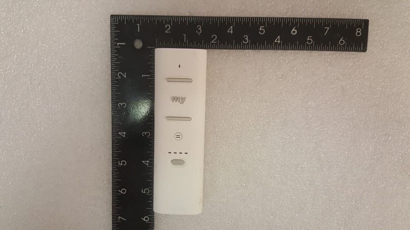
DWNV2TDBU
Oct 02, 2024Ysia 5 TDBU HP Zigbee 5175066A
Equipment Class
DTS - Digital Transmission System