DWNVARBLYsia 5 Variation HP Zigbee II, 5171079B
Somfy Systems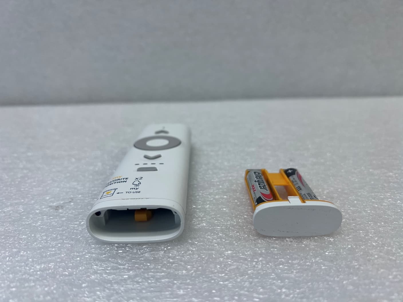
Click to zoom
Application Details
- Equipment Class
- DTS - Digital Transmission System
- Date of Grant
- Aug 18, 2026
- Application Purpose
- Original Equipment
- Equipment Note
- Ysia 5 Variation HP Zigbee II, 5171079B
- Frequency Range
- 2402.00000000 - 2480.00000000
- Company
- Somfy Systems
- Country
- United States
Documents & Files
Document Text
Text extracted from the exhibit documents filed with the FCC. Open a document above to read the original.
Users Manual
1 [A] a h b j e g f c d i k ___ [B] 1 2 3 4 5 ___ [C] 34112 ___ [D] 1 3 2 4 ___ Copyright ©2024 - 2026. All rights reserved. SOMFY ACTIVITÉS SA, Société Anonyme, capital 35.000.000 Euros, RCS Annecy 303.970.230. Images non contractually binding.01/2026 EN Complete instruction guide (settings, tips and advice) available online on https://www.somfy.info/fr/p/Ysia Please read this guide carefully before installing or using this product. Please also comply with the instructions set out in the enclosed Safety instructions document. 1. In detail (Figure } [A] ) a)Feedback LED b)Up button (to raise, switch on or open the motorised product) c)Variator (to tilt the slats or vary the lighting or heating) d)Stop/my button (allows the motorised product to be stopped or moved to the favourite position by pressing the button twice in succession) e)Down button (to lower, switch off or close the motorised product) f)Selected channel feedback LED Channel or group select LEDs (Ysia 5 Variation only) g)Channel selector Channel or group selector (Ysia 5 Variation only) h)PROG button i)Batteries holder latch j)Wall bracket k)Batteries holder 2. Start-up Download the TaHoma application if it is not yet installed on the smartphone. 3. Selection of groups (Figure } [B] ) Before using Ysia Zigbee, check that the correct group has been selected. 4. Installation 4.1. Adding/Deleting Ysia Zigbee Follow the instructions on the TaHoma application to add or remove a Ysia Zigbee. 4.2. Wall mounting ( Figure } [C]) Open the wall mount (i) and fix it to a flat surface using a screwdriver and an M3-type screw. CAUTION Do not use an electric screwdriver. 5. Replacing the batteries (Figure } [D] ) DANGER Read the Safety instructions document. Explosion risk if the battery is replaced by an incorrect type. Do not mix old and new batteries. Insert the batteries type AAA LR03, 2 x 1.5 V, as indicated by the polarity markings (+ and - signs) in the battery compartment. The power supply terminals must not be short-circuited. 6. Technical data Frequency range used: 2.4 GHz - 2.4835 GHz. US and Canada maximum e.r.p. < 100 mW. Other countries maximum e.r.p.< 10 mW. The environment in which the product is used might reduce the radio range. The use in the same room as the controlled products is recommended. Radio range: 50 m in Free field (optimal condition). Operating temperature: 0 °C (+32 °F) to +48 °C (+118.4 °F). Power supply: 2 x type AAA LR03 batteries, 2 x 1.5 V. SOMFY ACTIVITES SA, 74300 CLUSES FRANCE hereby declares that the radio equipment covered by these instructions is in compliance with the requirements of Radio Directive 2014/53/EU and the other essential requirements of the applicable European Directives. The full text of the EU Declaration of Conformity is available at www.somfy.com/ce. The Bluetooth® word mark and logos are registered trademarks owned by the Bluetooth SIG, Inc. and any use of such marks by SOMFY ACTIVITES SA is under license. Other trademarks and trade names are those of their respective owners. FR Notice complète (réglages, conseils et astuces) disponible en ligne sur https://www.somfy.info/fr/p/Ysia Avant d’installer et d’utiliser ce produit, lire attentivement la présente notice. Respecter également les consignes détaillées dans le document joint Notice de sécurité. 1. En détail (figure } [A] ) a)LED de feedback b)Bouton Montée (pour monter, allumer ou ouvrir le produit motorisé) c)Variateur (pour orienter les lames ou varier l’éclairage ou le chauffage) d)Bouton Stop/my (pour arrêter le produit motorisé ou, avec deux appuis brefs et consécutifs, l’amener en position favorite). e)Bouton Descente (pour descendre, éteindre ou fermer le produit motorisé) f)LED de feedback de canal sélectionné LED de confirmation du canal ou groupe choisi (Ysia 5 Variation uniquement). g)Sélecteur de canal Sélecteur de canal ou de groupe (Ysia 5 Variation uniquement). h)Bouton PROG i)Bouton de libération du compartiment à piles. j)Support mural k)Compartiment à piles. 2. Mise en route Télécharger l’application TaHoma si elle n’est pas encore installée sur le smartphone. 3. Sélection des groupes (figure } [B] ) Avant toute opération avec la télécommande Ysia 5 Variation HP Zigbee, s’assurer que le bon groupe est sélectionné. 4. Installation 4.1. Ajout/suppression d'Ysia Zigbee Suivre les consignes sur l’application TaHoma pour ajouter ou supprimer une Ysia Zigbee. 4.2. Support mural ( figure } [C]) Ouvrir le support mural (i) et le fixer sur une surface plane à l’aide d’un tournevis et d’une vis de type M3. ATTENTION Ne pas utiliser un tournevis électrique. 5. Remplacement des piles (figure } [D] ) DANGER Lire le document Consignes de sécurité. Risque d’explosion si la pile est remplacée par un type incorrect. Ne pas mixer des piles usagées et des piles neuves. Insérer des piles de type AAA LR03, 2 x 1.5 V, conformément aux indications de polarité (signes + et -) dans le compartiment à piles. Les bornes d’alimentation ne doivent pas être court- circuitées. 6. Caractéristiques techniques Gamme de fréquences utilisée : 2.4 GHz - 2.4835 GHz. US et Canada e.r.p. maximum < 100 mW. Autres pays e.r.p. maximum< 10 mW. L’environnement dans lequel le produit est utilisé peut réduire la portée radio. L'utilisation dans la même pièce que les produits commandés est conseillée. Portée radio : 50 m en champ libre (condition optimale). Température de fonctionnement : 0 °C (+32 °F) à +48 °C (+118.4 °F). Alimentation : 2 x piles du type AAA LR03, 2 x 1.5 V. Par la présente, SOMFY ACTIVITES SA, 74300 CLUSES FRANCE déclare que l’équipement radio couvert par ces instructions est conforme aux exigences de la Directive Radio 2014/53/UE et aux autres exigences essentielles des Directives européennes applicables. Le texte complet de la déclaration UE de conformité est disponible sur www.somfy.com/ce. La marque et les logos Bluetooth® sont des marques déposées appartenant à Bluetooth SIG, Inc. et toute utilisation de ces marques par SOMFY ACT…
Text truncated - open the document above for the full version.
Users Manual
2 EL Πλήρης οδηγός εγκατάστασης (ρυθμίσεις, υποδείξεις και συμβουλές) διατίθενται online στον ιστότοπο https:// www.somfy.info/fr/p/Ysia Πριν από την εγκατάσταση ή τη χρήση αυτού του προϊόντος, διαβάστε προσεκτικά το παρόν εγχειρίδιο. Τηρείτε επίσης τις οδηγίες που αναφέρονται αναλυτικά στο συνημμένο έγγραφο Οδηγίες ασφαλείας. 1. Αναλυτικά (Σχήμα } [A]) a)LED ανατροφοδότησης b)Κουμπί Επάνω (για ανέβασμα, ενεργοποίηση ή άνοιγμα του ηλεκτροκίνητου προϊόντος) c)Ρυθμιστής (για κλίση των πτερυγίων ή μεταβολή του φωτισμού ή της θέρμανσης) d)Κουμπί Stop/my (Επιτρέπει τη διακοπή λειτουργίας ή τη μετακίνηση του ηλεκτροκίνητου προϊόντος στην αγαπημένη θέση με πάτημα του κουμπιού δύο φορές διαδοχικά) e)Κουμπί Κάτω (για κατέβασμα, απενεργοποίηση ή κλείσιμο του ηλεκτροκίνητου προϊόντος) f)LED ανατροφοδότησης επιλεγμένου καναλιού LED επιλογής καναλιού ή ομάδας (Ysia 5 Variation μόνο) g)Επιλογέας καναλιού Επιλογέας καναλιού ή ομάδας (Ysia 5 Variation μόνο) h)Κουμπί PROG i)Μάνδαλο θήκης μπαταριών j)Επιτοίχια βάση k)Θήκη μπαταριών 2. Εκκίνηση Κατεβάστε την εφαρμογή TaHoma, αν δεν είναι ακόμα εγκατεστημένη στο smartphone. 3. Επιλογή ομάδων (Σχήμα } [B]) Πριν από οποιονδήποτε χειρισμό με το τηλεχειριστήριο Ysia 5 Variation HP Zigbee, βεβαιωθείτε ότι είναι επιλεγμένη η σωστή ομάδα. 4. Εγκατάσταση 4.1. Προσθήκη/Διαγραφή Ysia Zigbee Ακολουθήστε τις οδηγίες της εφαρμογής TaHoma για να προσθέσετε ή να αφαιρέσετε ένα Ysia Zigbee. 4.2. Επιτοίχια βάση (Σχήμα } [C]) Ανοίξτε την επιτοίχια βάση (i) και στερεώστε την σε επίπεδη επιφάνεια χρησιμοποιώντας ένα κατσαβίδι και μια βίδα τύπου M3. ΠΡΟΣΟΧΗ Μην χρησιμοποιήσετε ηλεκτρικό κατσαβίδι. 5. Αντικατάσταση των μπαταριών (Σχήμα } [D]) ΚΙΝΔΥΝΟΣ Διαβάστε το έγγραφο Οδηγίες ασφαλείας. Κίνδυνος έκρηξης σε περίπτωση αντικατάστασης της μπαταρίας με μπαταρία εσφαλμένου τύπου. Μη χρησιμοποιείτε μαζί παλιές και καινούργιες μπαταρίες. Τοποθετήστε μπαταρίες τύπου AAA LR03, 2 x 1.5 V, όπως υποδεικνύεται από τις σημάνσεις πολικότητας (σύμβολα + και -) στο διαμέρισμα μπαταριών. Οι ακροδέκτες τροφοδοσίας δεν πρέπει να είναι βραχυκυκλωμένοι. 6. Τεχνικά χαρακτηριστικά Χρησιμοποιούμενη περιοχή συχνοτήτων: 2.4 GHz - 2.4835 GHz. ΗΠΑ και Καναδάς, μέγιστη e.r.p.< 100 mW. Άλλες χώρες, μέγιστη e.r.p.< 10 mW. Το περιβάλλον στο οποίο χρησιμοποιείται το προϊόν μπορεί να μειώσει την εμβέλεια ραδιοεπικοινωνίας. Συνιστάται να χρησιμοποιείται στον ίδιο χώρο με τα ελεγχόμενα προϊόντα. Εμβέλεια ραδιοεπικοινωνίας: 50 m σε ανοιχτό χώρο (βέλτιστη κατάσταση). Θερμοκρασία λειτουργίας: 0 °C (+32 °F) έως +48 °C (+118.4 °F). Τροφοδοσία: 2 x μπαταρίες τύπου AAA LR03, 2 x 1.5 V. Με την παρούσα, η SOMFY ACTIVITES SA, 74300 CLUSES FRANCE δηλώνει ότι ο ραδιοεξοπλισμός που καλύπτεται από αυτές τις οδηγίες συμμορφώνεται με τις απαιτήσεις της οδηγίας 2014/53/ΕΕ για τον ραδιοεξοπλισμό και λοιπές ουσιώδεις απαιτήσεις των εφαρμοζόμενων ευρωπαϊκών οδηγιών. Το πλήρες κείμενο της δήλωσης συμμόρφωσης ΕΕ διατίθεται στον ιστότοπο www.somfy.com/ce. Το λεκτικό σήμα και οι λογότυποι Bluetooth® είναι κατατεθέντα σήματα τα οποία ανήκουν στην Bluetooth SIG, Inc., και οποιαδήποτε χρήση τέτοιων σημάτων από την SOMFY ACTIVITES SA υπόκειται σε άδεια. Άλλα εμπορικά σήματα και εμπορικές ονομασίες ανήκουν στους αντίστοιχους κατόχους τους. PT Guia de instruções completo (definições, sugestões e consel- hos) disponível online em https://www.somfy.info/fr/p/Ysia Antes de instalar e utilizar o produto, leia atentamente estas instruções. Também devem ser respeitadas as instruções detalhadas apresentadas no documento Instruções de segurança em anexo. 1. Em detalhe (Figura } [A]) a)LED de feedback b)Botão Subida (para subir, ligar ou abrir o produto motorizado) c)Variador (para inclinar as lâminas ou variar a iluminação ou o aquecimento) d)Botão Parar/my (Permite que o produto motorizado seja parado ou movido para a posição preferida premindo o botão duas vezes seguidas) e)Botão Descida (para descer, desligar ou fechar o produto motorizado) f)LED de feedback do canal selecionado LEDs de seleção de canal ou grupo (apenas Ysia 5 Variation) g)Seletor de canal Seletor de canal ou grupo (apenas Ysia 5 Variation) h)Botão PROG i)Fecho do porta-pilhas j)Suporte de parede k)Porta-pilhas 2. Arranque Descarregue a aplicação TaHoma, caso ainda não a tenha instalado no smartphone. 3. Seleção de grupos (Figura } [B]) Antes de qualquer operação com o comando à distância Ysia 5 Variation HP Zigbee, certifique-se de que seleccionou o grupo correto. 4. Instalação 4.1. Adicionar/apagar Ysia Zigbee Siga as instruções na aplicação TaHoma para adicionar ou remover um dispositivo Ysia Zigbee. 4.2. Suporte de parede (Figura } [C]) Abra o suporte de parede (i) e fixe-o a uma superfície plana, utilizando uma chave de parafusos e um parafuso do tipo M3. ATENÇÃO Não use uma chave de parafusos elétrica. 5. Substituir as baterias (Figura } [D]) PERIGO Leia o documento Instruções de segurança. Risco de explosão se a pilha for substituída por uma de tipo incorreto. Não misture pilhas usadas com novas. Insira as baterias do tipo AAA LR03, 2 x 1.5 V, conforme indicado pelas marcas de polaridade (sinais + e -) no compartimento das baterias. Os bornes de alimentação não devem estar em curto-circuito. 6. Características técnicas Gama de frequências utilizada: 2.4 GHz - 2.4835 GHz. e.r.p. máxima nos EUA e Canadá < 100 mW. e.r.p. máxima nos outros países < 10 mW. O ambiente onde o produto é utilizado pode reduzir o alcance de rádio. Recomenda-se a utilização na mesma divisão que os produtos controlados. Alcance rádio: 50 m em campo livre (condições ideais). Temperatura de utilização: 0 °C (+32 °F) a +48 °C (+118.4 °F). Alimentação: 2 x pilhas do tipo AAA LR03, 2 x 1.5 V. Pela presente, a SOMFY ACTIVITES SA, 74300 CLUSES FRANCE declara que o equipamento de rádio abrangido por estas instruções está conforme as exigências da Diretiva de Equipamentos de Rádio 2014/53/UE e as restantes exigências essenciais das Diretivas Europeias aplicáveis. O texto completo da declaração de conformidade U…
Text truncated - open the document above for the full version.
Attestation Statements
Somfy Systems, Inc., 121 Herrod Blvd., Dayton, NJ 08810 CFR 47 §2.911 (d)(7) Agent Designation Attestation Date: 06-30-2026 FCC ID: DWNVARBL To: Federal Communications Commission 7435 Oakland Mills Road Columbia, MD 21046 USA Somfy Systems, Inc. (“t he applicant”) as required by section 2.911(d)(7), will also serve as the agent for service of process for the above referenced FCC ID. The applicant acknowledges that they will maintain an agent for no less than one year after the grantee has terminated all marketing and importation or the conclusion of any Commission-related proceeding involving the equipment. The applicant further acknowledges their responsibility to inform the FCC whenever the agent information changes. Contact Person: Jim Hellander Company Name: Somfy Systems, Inc. ( FRN# 0006579940) Company US Address: 121 Herrod Blvd., Dayton, NJ 08810 Email: [email protected] Sincerely yours, Jim Hellander
Attestation Statements
Somfy Systems, Inc. 121 Herrod Blvd., Dayton, NJ 08810 Federal Communications Commission Authorization and Evaluation Division 7435 Oakland Mills Road Columbia, MD 21046 USA Date: 07/20/26 Ref: Attestation Statements Part 2.911(d)(5)(i) Filing FCC ID: DWNVARBL Somfy Systems, inc. (“the applicant”) certifies that the equipment for which authorization is sought is not “covered” equipment prohibited from receiving an equipment authorization pursuant to section 2.903 of the FCC rules. Somfy Systems, Inc. (“the applicant”) certifies that the equipment for which authorization is sought does not include cybersecurity or anti-virus software produced or provided by Kaspersky Lab, Inc. or any of its successors and assignees, including equipment with integrated Kaspersky Lab, Inc. (or any of its successors and assignees) cybersecurity or anti-virus software pursuant to DA-24-886 and KDB 986446 D01 Covered Equipment Guidance section B(2a). Device is inherently compliant based on hardware limitations or software controls. or A Software Bill of Materials (SBOM) is provided to the TCB for review, and The end-user or third parties cannot install additional software on this device. Sincerely, Jim Hellander Somfy Systems, Inc. 121 Herrod Blvd., Dayton, NJ 08810 Federal Communications Commission Authorization and Evaluation Division 7435 Oakland Mills Road Columbia, MD 21046 USA Date: 07-17-25 Ref: Attestation Statements Part 2.911(d)(5)(ii) Filing FCC ID: DWNVARBL Somfy Systems, Inc. (“the applicant”) certifies that, as of the date of the filing of the application, the applicant is not identified on the Covered List (as a specifically named entity or any of its subsidiaries or affiliates) as an entity producing “covered” equipment. Sincerely, Jim Hellander
Cover Letter(s)
July 20, 2026 FCC ID: DWNVARBL IC ID: 12049A-VARBL FCC and IC Confidentiality Request In accordance with 0.459 & 0.457 of CFR 47, please, accept this letter as an official request to have the schematics, block diagram, operational description of the EUT treated as confidential. The information contained within is a result of extensive investment and development effort by Somfy Systems, Inc. and its disclosure will compromise Somfy's Intellectual Property and competitive edge. We thus ask the FCC and IC NOT to publish the information mentioned above, in order to protect Somfy's Intellectual Property. Regards, Somfy Systems, Inc. Jim Hellander Electronics Engineer
Cover Letter(s)
Somfy Systems, Inc. 121 Herrod Blvd., Dayton, NJ 08810 July 20, 2026 To Whom it may Concern: I, the undersigned, hereby authorize, Wei Li, Advanced Compliance Lab, to act on behalf of Somfy Systems, inc. in all matters to the current FCC and ISED applications for authorization, including signing of all documents relating to these matters. Sincerely, Jim Hellander Somfy Systems, Inc. FRN# 0006579940 [email protected]
Cover Letter(s)
Date: July 31, 2026 Ref: Application for FCC & ISED Certification on Somfy Tx under FCC ID: DWNVARBL IC: 12049A-VARBL Ctrl#: 0048-260731-02 From: Wei Li, Advanced Compliance Laboratory To Whom It May Concern: Dear Sir/ Madam, We, Advanced Compliance Laboratory, as EMC testing lab and agent, would like to represent the applicant, Somfy Systems to apply for your approval on product authorization for New Single Certification under FCC ID: DWNVARBL & IC: 12049A-VARBL. The investigation for the EMC performance of the EUT(s), Ysia 5 Variation HP Zigbee II, Model Number: 5171079B was performed in July, 2026 on behalf of the applicant. It was found that EUTs comply with the requirements of current FCC Part 15.247 & ISED RSS-247, RSS-Gen. The system was configured as the typical condition during the test. The measurement facility used to collect the test data is located at Hillsborough, New Jersey. OATS was listed by IC as “Site 3130A”. In addition, this testing site has been listed by FCC (US3288) since 1992 and also recognized under ANAB Accreditation ( Cert. No.: AT-3288). Should you need more information, please contact me at (908) 392-3378 or email me to [email protected]. Your attention is highly appreciated. Sincerely, Wei Li Manager Advanced Compliance Laboratory, Inc. 210 Cougar Court Hillsborough, NJ 08844 Tel: (908) 927 9288 Fax: (908) 927 0728 Advanced Compliance Lab
External Photos
07/29/26 121 Herrod Blvd., Dayton, NJ 08810 External Product Photos Transmitter Ysia 5 Variation HP Zigbee II HVIN 5171079B DWNVARBL IC: 12049A-VARBL 07/29/26 121 Herrod Blvd., Dayton, NJ 08810 FRONT VIEW 07/29/26 121 Herrod Blvd., Dayton, NJ 08810 BACK VIEW 07/29/26 121 Herrod Blvd., Dayton, NJ 08810 LEFT VIEW 07/29/26 121 Herrod Blvd., Dayton, NJ 08810 TOP VIEW 07/29/26 121 Herrod Blvd., Dayton, NJ 08810 RIGHT VIEW 07/29/26 121 Herrod Blvd., Dayton, NJ 08810 BOTTOM VIEW 07/29/26 121 Herrod Blvd., Dayton, NJ 08810 Battery Compartment Open View
ID Label/Location Info
Product Label DWNVARBL 12049A-VARBL 07/20/26 Label Label position indication Somfy Systems, Inc. 121 Herrod Blvd. Dayton, NJ 08810
Internal Photos
07/29/26 121 Herrod Blvd., Dayton, NJ 08810 Internal Product Photos Transmitter Ysia 5 Variation HP Zigbee II HVIN 5171079B DWNVARBL IC: 12049A-VARBL Transmitter Disassembled 07/29/26 121 Herrod Blvd., Dayton, NJ 08810 PCBA’s separated. Both sides show. 07/29/26 121 Herrod Blvd., Dayton, NJ 08810 07/29/26 121 Herrod Blvd., Dayton, NJ 08810 Sub Sections of PCBA’s for clarity 07/29/26 121 Herrod Blvd., Dayton, NJ 08810 07/29/26 121 Herrod Blvd., Dayton, NJ 08810
RF Exposure Info
EUT: Ysia 5 Variation HP Zigbee II Report No: 0048-260706-02 Model: 5171079B FCC ID: DWNVARBL IC : 12049A-VARBL Page 29 of 76 Advanced Compliance Laboratory, Inc. 210 Cougar Court, Hillsborough, NJ 08844, tel:(908) 927 9288 7.3 MAXIMUM PERMISSIBLE EXPOSURE LIMITS for FCC RF Exposure Evaluation §1.1310 The criteria listed in Table 1 shall be used to evaluate the environmental impact of human exposure to radio-frequency (RF) radiation as specified in §1.1307(b), except in the case of portable devices which shall be evaluated according to the provisions of §2.1093 of this chapter. LIMITS for FCC SAR Evaluation KDB 447498 D04 Interim General RF Exposure Guidance v01, section 2.1.3 SAR-Based Exemption: “A more comprehensive exemption, considering a variable power threshold that depends on both the separation distance and power, is provided in § 1.1307(b)(3)(i)(B). This exemption is applicable to the frequency range between 300 MHz and 6 GHz, with test separation distances between 0.5 cm and 40 cm, and for all RF sources in fixed, mobile, and portable device exposure conditions.” For 100 MHz to 6 GHz and test separation distances ≤ 50 mm, the 1-g and 10-g SAR test exclusion thresholds are determined by the following: [(max. power of channel, including tune-up tolerance, mW) / (min. test separation distance, mm)] · [√f(GHz)] ≤ 3.0 for 1-g SAR, and ≤ 7.5 for 10-g extremity SAR, where f(GHz) is the RF channel transmit frequency in GHz FCC KDB 447498 D01 General RF Exposure Guidance v06, section 4.3.1 & Appendix A provides the SAR Test Exclusion Thresholds (ERP/Conducted) to verify that the device is exempt from 1-g extremity SAR at different separation distances. As example, for 900MHz Tx: 16mW (12dBm); For 2450MHz Tx: 10mW (10dBm) at ≤5 mm. EUT: Ysia 5 Variation HP Zigbee II Report No: 0048-260706-02 Model: 5171079B FCC ID: DWNVARBL IC : 12049A-VARBL Page 30 of 76 Advanced Compliance Laboratory, Inc. 210 Cougar Court, Hillsborough, NJ 08844, tel:(908) 927 9288 Details in calculation formula for reference, given in § 1.1307(b)(3)(i)(B) to calculate the exemption: LIMITS per ISED RSS-102 (issue 6) Section 6.3 & Table 11 for Exemption Limits for Routine Evaluation — SAR Evaluation For limb-worn devices where the 10 gram value applies, the exemption limits for routine evaluation in Table 1 are multiplied by a factor of 2.5. Example: Exclusion Thresholds to verify that the 2450MHz Tx is exempt from 1-g SAR at separation distance of ≤5 mm: 3mW (4.77dBm) & 10-g SAR at separation distance of ≤5 mm: 7.5mW (8.75dBm). EUT: Ysia 5 Variation HP Zigbee II Report No: 0048-260706-02 Model: 5171079B FCC ID: DWNVARBL IC : 12049A-VARBL Page 31 of 76 Advanced Compliance Laboratory, Inc. 210 Cougar Court, Hillsborough, NJ 08844, tel:(908) 927 9288 Section 5.3.2 Table 7&8 for Exemption Limits for Routine Evaluation – RF Exposure Evaluation (10MHz ro300GHz) In these cases, the information contained in the RF exposure technical brief may be limited to information that demonstrates how the e.i.r.p. was derived. Summary For FCC and IC, that max. declared power level can be modified by any duty cycle over the time averaging period. Time-averaging period is a time period not to exceed 30 minutes for fixed RF sources or a time period inherent from device transmission characteristics not to exceed 30 minutes for mobile and portable RF sources. For rf exposure, the averaging period is 6 minutes for ISED Canada and for FCC it varies by frequency but 1~60 second for RF exposure or the period specified by product design spec. for RF exposure can be used. So the power value for RF exposure= Declared power x Duty Cycle factor EUT: Ysia 5 Variation HP Zigbee II Report No: 0048-260706-02 Model: 5171079B FCC ID: DWNVARBL IC : 12049A-VARBL Page 32 of 76 Advanced Compliance Laboratory, Inc. 210 Cougar Court, Hillsborough, NJ 08844, tel:(908) 927 9288 CALCULATIONS for MPE distance and Power Density Given E = (30 * P * G) / d and S = E ^ 2 / 3770 where E = Field Strength in Volts/meter P = Power in Watts G = Numeric antenna gain d = Distance in meters S = Power Density in milliwatts/square centimeter Combining equations and rearranging the terms to express the distance as a function of the remaining variables yields: d = ((30 * P * G) / (3770 * S)) Changing to units of Power to mW and Distance to cm, using: P(mW) = P (W) / 1000 and d (cm) =100 * d (m) yields d = 100 * ((30 * (P / 1000) * G) / (3770 * S)) d = 0.282 * (P * G / S) where d = distance in cm P = Power in mW G = Numeric antenna gain S = Power Density in mW/cm^2 Substituting the logarithmic form of power and gain using: P (mW) = 10 ^ (P (dBm) / 10) and G (numeric) = 10 ^ (G (dBi) / 10) yields d = 0.282 * 10 ^ ((P + G) / 20) / S Equation (1) S = 0.0795 * 10 ^ ((P + G)/10)/ d^2 Equation (2) where d = MPE distance in cm P = Power in dBm G = Antenna Gain in dBi S = Power Density Limit in mW/cm^2 Equation (1) and the measured Output power is used to calculate the MPE distance. Equation (2) and the measured Output power is used to calculate the Power density. EUT: Ysia 5 Variation HP Zigbee II Report No: 0048-260706-02 Model: 5171079B FCC ID: DWNVARBL IC : 12049A-VARBL Page 33 of 76 Advanced Compliance Laboratory, Inc. 210 Cougar Court, Hillsborough, NJ 08844, tel:(908) 927 9288 APPLICABLE LIMITS RF MPE for separation >= 20cm FCC: From §1.1310 Table 1 (B), for Public S = 1.0 mW/cm 2 (for Professional, S = 5.0 mW/cm 2 ) IC: Per RSS-102, Sec. 5.3.2 Table 7, With formula of 2.619 x 10 -2 ƒ 0.6834 W/m 2 , most restricted power density limit values are 2.74W/m 2 at 902MHz, 5.34W/m 2 at 2400MHz. SAR Exclusion Thresholds for separation ≤5~40cm: FCC : Use Formular in FCC § 1.1307(b)(3)(i)(B) & KDB 447498 D04 IC: Use RSS-102 Table11 Apply duty cycle factor & 2.5 factor for extremity or limb-worn devices EUT: Ysia 5 Variation HP Zigbee II Report No: 0048-260706-02 Model: 5171079B FCC ID: DWNVARBL IC : 12049A-VARBL Page 34 of 76 Advanced Compliance Laboratory, Inc. 210 Cougar Court, Hi…
Text truncated - open the document above for the full version.
Test Report
EUT: Ysia 5 Variation HP Zigbee II Report No: 0048-260706-02 Model: 5171079B FCC ID: DWNVARBL IC : 12049A-VARBL Page 1 of 76 Advanced Compliance Laboratory, Inc. 210 Cougar Court, Hillsborough, NJ 08844, tel:(908) 927 9288 FCC CFR47 PART 15 SUBPART C & IC RSS-247 TEST REPORT For SOMFY SYSTEMS INC. Ysia 5 Variation HP Zigbee II Model Number: 5171079B FCC ID: DWNVARBL IC: 12049A-VARBL Report Number: 0048-260706-02 Prepared for SOMFY SYSTEMS INC. 121 Herrod Blvd. Dayton, NJ 08810 USA Prepared by Advanced Compliance Laboratory, Inc. 210 Cougar Court Hillsborough, NJ 08844 Tel: (908) 927 9288 Fax: (908) 927 0728 Date: 07/31/2026 210 Cougar Court Hillsborough, NJ 08844 Tel: (908) 927 9288 Fax: (908) 927 0728 Advanced Compliance Laboratory EUT: Ysia 5 Variation HP Zigbee II Report No: 0048-260706-02 Model: 5171079B FCC ID: DWNVARBL IC : 12049A-VARBL Page 2 of 76 Advanced Compliance Laboratory, Inc. 210 Cougar Court, Hillsborough, NJ 08844, tel:(908) 927 9288 TABLE OF CONTENTS 1. TEST RESULT CERTIFICATION ............................................................................................ 3 2. EUT DESCRIPTION .................................................................................................................. 5 3. TEST METHODOLOGY ........................................................................................................... 7 4. FACILITIES AND ACCREDITATION .................................................................................... 7 5. CALIBRATION AND UNCERTAINTY ................................................................................... 8 5.1. MEASURING INSTRUMENT CALIBRATION ............................................................. 8 5.2. MEASUREMENT UNCERTAINTY ................................................................................ 8 5.3. TEST AND MEASUREMENT EQUIPMENT ................................................................. 9 6. SETUP OF EQUIPMENT UNDER TEST ............................................................................... 10 7. APPLICABLE LIMITS AND TEST RESULTS ...................................................................... 11 7.1 6dB &99% BANDWIDTH .............................................................................................. 11 7.2 PEAK OUTPUT POWER ................................................................................................. 15 7.3 MAXIMUM PERMISSIBLE EXPOSURE ...................................................................... 29 7.4 AVERAGE OUTPUT POWER ........................................................................................ 35 7.5 PEAK POWER SPECTRAL DENSITY .......................................................................... 36 7.6 CONDUCTED SPURIOUS EMISSIONS ........................................................................ 40 7.7 RADIATED EMISSIONS ................................................................................................ 51 7.7.1. TRANSMITTER RADIATED SPURIOUS EMISSIONS ........................................ 51 7.7.2. TRANSMITTER RADIATED EMISSIONS DATA ................................................ 53 7.8 CONDUCTED EMISSION ................................................................................................ 62 7.9 EUT RECEIVING MODE VERIFICATION ..................................................................... 63 8. SETUP PHOTOS ...................................................................................................................... 64 9. APPENDIX ............................................................................................................................... 68 EUT: Ysia 5 Variation HP Zigbee II Report No: 0048-260706-02 Model: 5171079B FCC ID: DWNVARBL IC : 12049A-VARBL Page 3 of 76 Advanced Compliance Laboratory, Inc. 210 Cougar Court, Hillsborough, NJ 08844, tel:(908) 927 9288 1. TEST RESULT CERTIFICATION COMPANY NAME: SOMFY SYSTEMS INC. EUT DESCRIPTION: Ysia 5 Variation HP Zigbee II MODEL: 5171079B DATE TESTED: 07/06/2026 to 07/31/2026 APPLICABLE STANDARDS STANDARD TEST RESULTS FCC Part 15.247 & IC RSS-247:Issue 4 & RSS-Gen Issue 5 NO NON-COMPLIANCE NOTED Test Summary Testing Items Per FCC Part 2/ Part 15.247 & IC RSS-247 /RSS-Gen Standard Requirements for DTS Modulation Section Limit Result DTS Bandwidth 15.247(a) (2) RSS-247, 5.2(a) >=500KHz Complies Peak Power Limit 15.247(b) (3) RSS-247, 5.4(d) Conducted: 1W (30dBm) e.i.r.p. 4W(36dBm) Complies Peak Power Spectral Density 15.247(e) RSS-247, 5.2(b) 8dBm/3KHz Complies Emissions ( Conducted) 15.247(d) RSS-247, 5.5 -20dB/-30dB Complies Spurious ( Radiated) 15.205(a) RSS-247, 5.5 15.209/RSS-Gen Complies RF Safety* 1.1310/RSS-102 1.0/5.0 mW/cm 2 Complies NOTE: *For mobile or fixed location transmitters, the minimum separation distance is 20 cm, even if calculations indicate that the MPE distance would be less. Advanced Compliance Laboratory, Inc. tested the above equipment in accordance with the requirements set forth in the above standards. The test results show that the equipment tested is capable of demonstrating compliance with the requirements as documented in this report. EUT: Ysia 5 Variation HP Zigbee II Report No: 0048-260706-02 Model: 5171079B FCC ID: DWNVARBL IC : 12049A-VARBL Page 4 of 76 Advanced Compliance Laboratory, Inc. 210 Cougar Court, Hillsborough, NJ 08844, tel:(908) 927 9288 Note : This document reports conditions under which testing was conducted and results of tests performed. This document may not be altered or revised in any way unless done so by A d v a n c e d C o m p l i a n c e L a b o r a t o r y , I n c . ( A C L ) and all revisions are duly noted i…
Text truncated - open the document above for the full version.
Contact Information
Applicant
James P Hellander(Industrial Operations Manager)
[email protected]Fax: 609-495-8153
Technical Contact
Somfy Systems, Inc.Jim Hellander
121 Herrod Blvd. · Dayton, New Jersey, 08810 · United States
Test Firm
Advanced Compliance Laboratory, Inc.Wei Li
Technical Specifications
| # | Rule Parts | Frequency Range | Power Output |
|---|---|---|---|
| 1 | 15C | 2.40 GHz - 2.48 GHz | 17.00 mW |
| 2 | 15C | 2.40 GHz - 2.48 GHz | 1.00 mW |
Other Applications from Somfy Systems
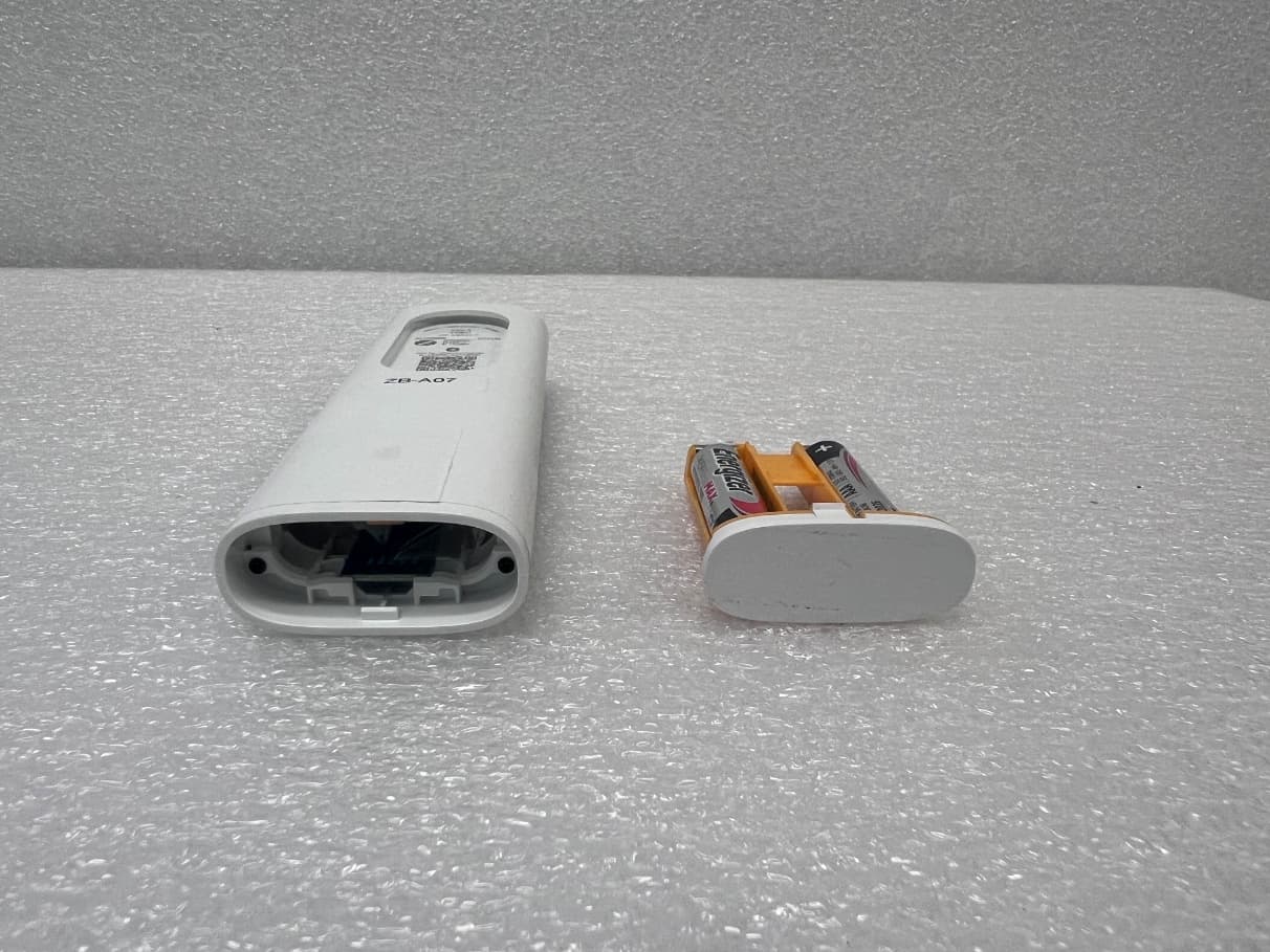
DWNV2TDBUBL
Aug 19, 2026Ysia 1, Ysia 5, Ysia 5 TDBU HP Zigbee II, 5175210B, 5175211B, 5175066B
Equipment Class
DTS - Digital Transmission System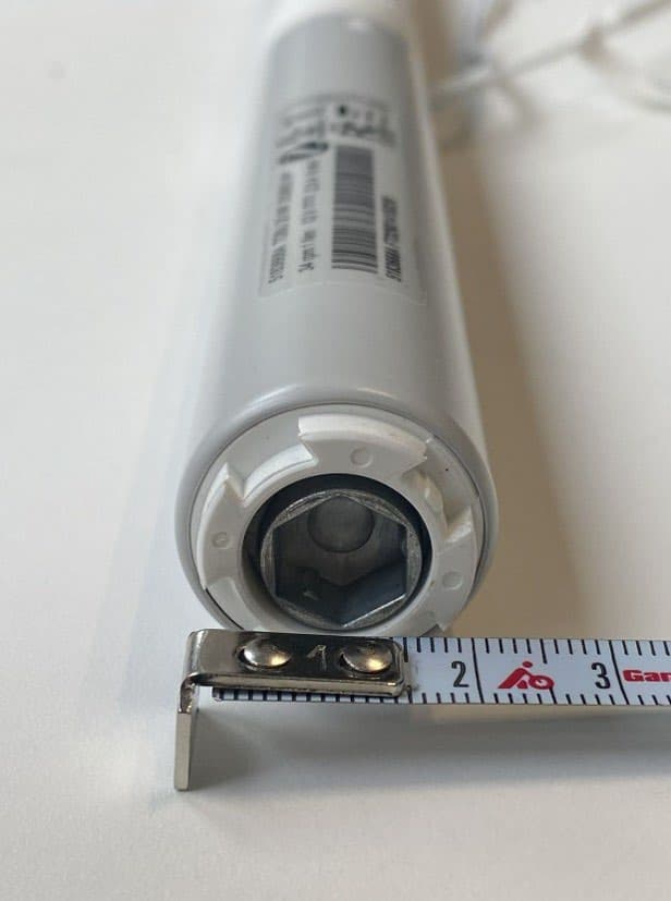
DWNTDBU25ZB
Jun 23, 2026TDBU 25 WF Zigbee HP 5183668
Equipment Class
DTS - Digital Transmission System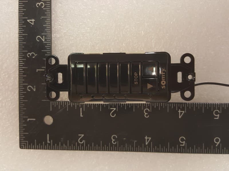
DWNDECOFLEX2
Feb 25, 2026Decoflex RTS In-Wall Mount 1810830
Equipment Class
DSC - Part 15 Security/Remote Control Transmitter
DWN-ROLLUPZB24
Sep 23, 2025ROLL UP2 24 Zigbee HP LI-ON 5178669
Equipment Class
DTS - Digital Transmission System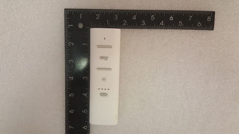
DWNV2TDBU
Oct 02, 2024Ysia 5 TDBU HP Zigbee 5175066A
Equipment Class
DTS - Digital Transmission System