DXAAC9200DECT HANDSET UNIT
Teledex LLC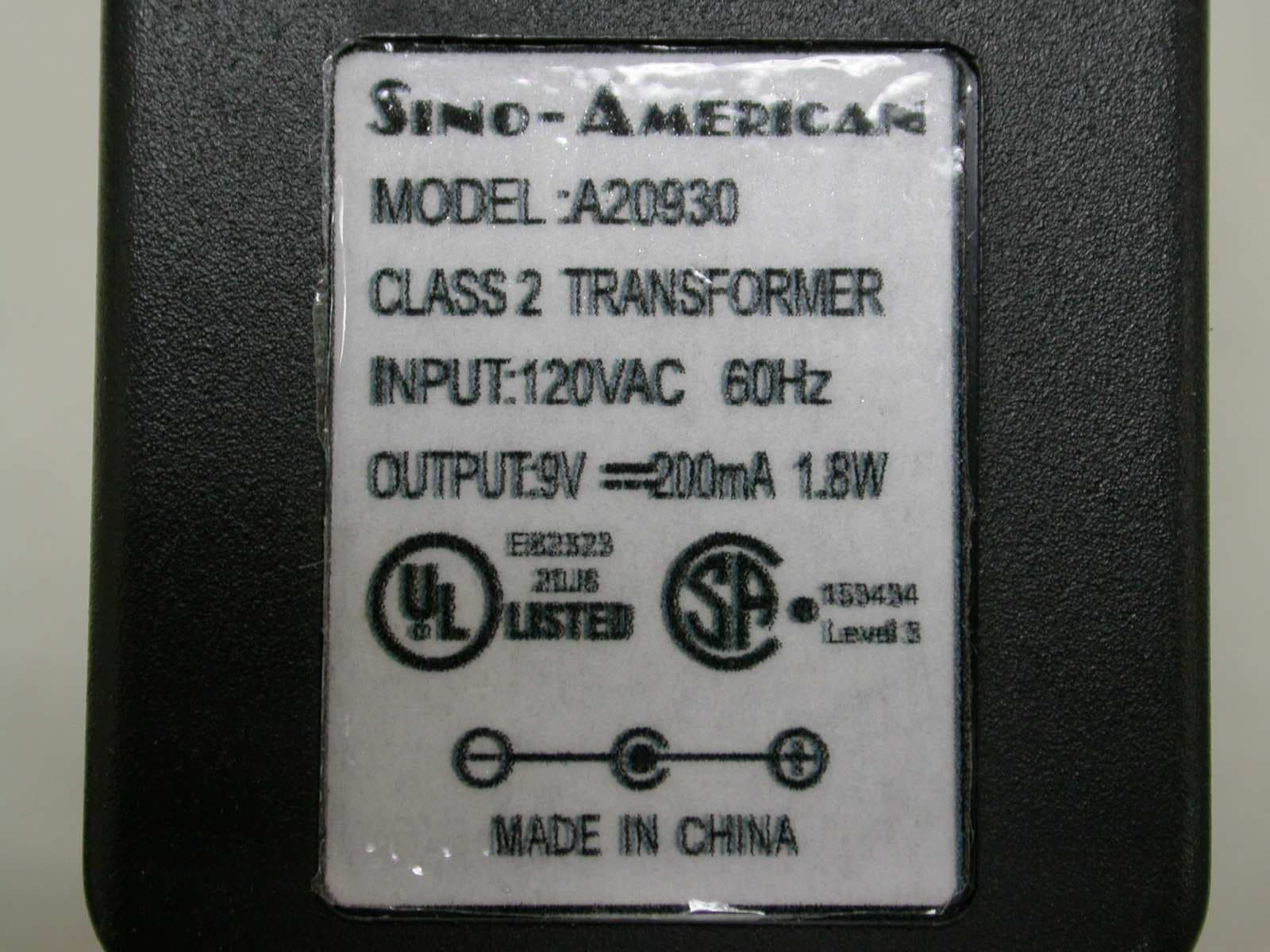
Click to zoom
Application Details
- Equipment Class
- PUE - Part 15 Unlicensed PCS portable Tx held to ear
- Date of Grant
- Sep 17, 2007
- Application Purpose
- Original Equipment
- Date of Application
- Sep 16, 2007
- Equipment Note
- DECT HANDSET UNIT
- Frequency Range
- 1921.53600000 - 1928.44800000
- Company
- Teledex LLC
- Country
- United States
Documents & Files
Document Text
Text extracted from the exhibit documents filed with the FCC. Open a document above to read the original.
Users Manual
iPhone DECT Cordless Series User Guide For Models AC8205S, AC8210S (1.8 GHz) and AC9205S, AC9210S (1.9 GHz) Preparing to Use the AC8200/AC9200 Series 1. Prepare to install the battery into the cordless handset by removing the battery cover and sliding it off. If cover is secured with a screw, remove the screw first. 2. Insert the battery connector into the handset’s connector. The connector is “keyed” so it only goes in one way. Do not force the connection. Note: The handset may “beep” when the battery is connected. This is not an indication that the telephone is ready to use. To obtain optimal performance of the telephone, be sure to charge the battery for 10 to 12 hours. 3. Replace the battery compartment cover and the retaining screw. 4. Insert the provided rubber screw cover. 5. Turn the telephone base so the back panel is facing you. Insert either end of the RJ-45 cable into the jack on the back of the telephone labeled LINE. 6. Insert the other end of the cable into the jack on the AC adapter labeled PHONE. 7. Insert one end of the RJ-11 line cord into the jack on the AC adapter labeled LINE. 8. Insert the other end of this line cord into a telephone jack. 9. Plug the AC adapter into an unswitched electrical outlet. 10. Remove the plastic overlay and place the paper faceplate (supplied separately) over the keys. Replace the plastic overlay by hooking the tabs on the overlay into the recessed slots located on both sides. 11. Place the cordless handset on the base unit. The handset/base registration process will occur. Handset/Base Registration Procedure This procedure establishes an exclusive link between a specific handset and base, thereby allowing no other access to this specific base. To accomplish this procedure, place the handset on the base in the charging position. The LINE indicator will blink while the registration process is occuring. This process only occurs the first time a handset is placed on the charging cradle of a new base. Charging the Battery The rechargeable Lithium-Polymer battery must be fully charged before using the phone for the first time. It is recommended that the battery be charged for approxi- mately 10 to 12 hours without interruption before use. To charge the battery, place the handset, keypad down, in the base unit. Ensure that the CHARGE LED on the base lights. If the LED Does Not Light: 1. Ensure that the AC adapter is plugged in. 2. Ensure that the AC adapter is plugged into an unswitched electrical outlet. 3. Ensure that the handset charging contacts at the bottom of the handset are making good contact with the base unit’s charging contacts. Cleaning the Battery Contacts To maintain a good charge, it is important to clean all charging contacts on the handset and base unit. Use a pencil eraser or other contact cleaner. Do not use any liquids or solvents. Battery Safety Instructions 1. Use only Teledex-approved battery replacements. 2. Dispose of the Lithium-Polymer battery in any ordinary trash receptacle. 3. Do not dispose of battery in fire, as it may explode. 4. Charge the battery only while in the handset, and only by using the base unit to charge. Do not attempt to remove the battery and charge it in a separate charging unit. 5. Do not short-circuit the battery, as this may cause it to explode or catch fire. Adjusting the Ring Volume and Assigning Ring Tones The UP and DOWN volume keys will adjust the ringer volume of the telephone. To adjust ring volume, press either the UP and DOWN volume key when the handset is on the bse cradle and the phone is not active (off-hook). There are four ring tones that can be assigned individually to either line (on two-line models) to audibly identify the ringing line. Additionally, the AC8200/AC9200 series features a programmable “crescendo” ring mode, wherein the ring volume begins at the lowest setting, then rings progressively louder with each ring during an incoming call. To assign a ring tone to a line (normal ring mode): 1. Press the FLASH key (see Fig. 1); then a key on the dial pad from 1-4, depending on the desired ring tone. The phone will ring once to provide a sample of the selected ring tone. 2. When you have selected a suitable ring tone, press the STORE key (see Fig. 1), then a number on the dial pad for the desired line assignment (i.e.; ‘1’ for line 1, ‘2’ for line 2). Cordless Handset AC Adapter Base Unit User Guide Lithium Polymer Battery Clear Plastic Overlay Rubber Battery Screw Cover Phillips Screw 15-foot, 8-wire Cable (with RJ-45 connector) 10-foot, 4-wire Line Cord (with RJ-11 connector) Included in Your Package To assign a ring tone to a line (crescendo ring mode): 1. Select desired ring tone: Press the FLASH key (see Fig. 1); then a key on the dial pad from 1-4, depending upon the desired ring tone. The phone will ring once to provide a sample of the selected ring tone. 2. Assign ring tone to a line: When you have selected a sui able ring tone, press the STORE key (see Fig. 1), then press number ‘3’ on the dial pad to assign the ring tone to line 1, or number ‘4’ on the dial pad to assign the ring tone to line ‘2’. To return to regular ring mode: 1. Press the FLASH key; then the number ‘1’ on the dial pad. 2. Press the STORE key; then the number on the keypad that corresponds to the line for which you wish to change back to regular ring mode. Adjusting Speakerphone Volume The speakerphone has eight (8) levels. To adjust speaker- phone volume, locate the volume up/down keys, located on the front of the phone to the left of the keypad. With the speaker active, press the “down” arrow key to decrease the volume level, and press the “up” arrow key to increase it. Adjusting Handset Receive Volume The handset has eight (8) volume levels. To adjust the handset volume, locate the volume up/down keys, located on the handset, below the “#” key. Pressing the UP arrow key will decrease the volume level, while pressing the DOWN arrow key will increase it. Auto Dial Keys The AC8200/AC9200 series…
Text truncated - open the document above for the full version.
Cover Letter(s)
Confidentiality Request Letter FCC ID: DXAAC9200 CANADA IC: 6I1A-AC9200 Device Name: iPhone Cordfess AC9200 Modef No: AC9105, AC9110, AC9105S' AC9110S AC9205, AC92r0, AC92055, AC9210S Date: 9rH August , 200-l Paf . Ranrraqf fnr Cnnf iricnf i:l itrr Dear Sir, I^lii-lr ra^^rd tn fho rafarancerl :nnlicef inn- TF,T,trDRC is reottestino YYfLrl'$vqlq Lv Lrvrrt confidentiality of certain sections of the accompanyi-ng documents. The documents for which TELEDEX is requesting confidentiafity are: This request is made under the provisions of Section 0.457(d) of the Commission's Rules and Section 552(b) (4) of the Freedom of Information Act. The material for which confidentiality is requested fal-l-s within the scope of Section 552(b) (4) as trade secrets incl-udes materia1 covered by Section 0.459 of the Commission's KK Hoh Fn^i n66r Teledex LLC 631 1 San Tonaci o Avenua San Jose, CA 95119 Tel: (408) 363-3100 Fax: (408) 363-3136 1. Bl-ock Diagram and Schematic Diagrams Schematic ? Anarrf i nn f)aqnri nf i nn vPv!qervrr TELEDEX LLC Headquarters: 631I San Ignacio Avenua San Jose. CA 951 19 Tel: (408) 363-3100 Fax: (408) 363-3136 i) CH. PD ii) TD6O14' MAIN SCH.PDF iii) TD6O1A HANDSET SCH PDF Te.l-edex Dect Tel-ephone Operation l16c^rlnll h PllF www.teledex.com Product Support Center,Malaysia. Unit lS,Lower Level 6, Hotel Equatorial Penang. I, Jalan Bukit Jambul, Bayan Lepas, I 1900 Penang, Malaysia. Tel: (604) 646-6326 Fax: (604) 646-8326 einnaralrr vf rrvv!vf J,
External Photos
FCC ID: DXAAC9200 07-07-MAS-113-01 IC ID: 617A-AC9200 Page A1 of A3 ANNEX A: EXTERNAL CONSTRUCTION PHOTOS OF EUT 1. Outside view 1 of EUT 2. Outside view 2 of EUT FCC ID: DXAAC9200 07-07-MAS-113-01 IC ID: 617A-AC9200 Page A2 of A3 3. Outside view 1 of charger 4. Outside view 2 of charger FCC ID: DXAAC9200 07-07-MAS-113-01 IC ID: 617A-AC9200 Page A3 of A3 5. Adaptor
Internal Photos
FCC ID: DXAAC9200 ETC Report No.: 07-07-MAS-113-01 IC ID: 617A-AC9200 Page B1 of B5 ANNEX B: INTERNAL CONSTRUCTION PHOTOS OF EUT 1. Inside View 1 of EUT 2. Inside View 2 of EUT FCC ID: DXAAC9200 ETC Report No.: 07-07-MAS-113-01 IC ID: 617A-AC9200 Page B2 of B5 3. Front view of PCB 4. Front view of PCB FCC ID: DXAAC9200 ETC Report No.: 07-07-MAS-113-01 IC ID: 617A-AC9200 Page B3 of B5 5. Rear view of PCB FCC ID: DXAAC9200 ETC Report No.: 07-07-MAS-113-01 IC ID: 617A-AC9200 Page B4 of B5 6. Inside View 1 of charger 7. Inside View 2 of charger FCC ID: DXAAC9200 ETC Report No.: 07-07-MAS-113-01 IC ID: 617A-AC9200 Page B5 of B5 8. Front view of PCB 9. Rear view of PCB
RF Exposure Info
Report No.: 07-07-MAS-113-03 Page 1 of 60 FCC ID: DXAAC9200 Electronics Testing Center, Taiwan (ETC) Rev. No.1.3 1 Report No.: 07-07-MAS-113-03 Client: TELEDEX LLC Product: US DECT Handset Model: AC9210S (Multiple Model List please see page 5.) Manufacturer/supplier: INVENTEC ELECTRONICS (M) SDN. BHD. Date test item received: 2007/07/13 Date test campaign completed: 2007/07/18 Date of issue: 2007/08/10 Test Result: ■ Compliance □ Not Compliance Statement of Compliance: The SAR values measured for the test sample are below the maximum recommended level of 1.6 W/kg averaged over any 1g tissue according to FCC OET Bulletin 65 Supplement C (Edition 01-01) and Industry Canada RSS-102 (Issue 2, 2005). The test result onl y corresponds to the tested sample. It is not permitted to copy this report, in part or in full, without the permission of the test laboratory. Total number of pages of this test report: 60 pages Test Engineer Eric Lin Checked by Joe Hsieh Approved by Winpo Tsai The testing described in this report has been carried out to the best of our knowledge and ability, and our responsibility is limited to the exercise of reasonable care. This certification is not intended to believe the sellers from their legal and/or contractual obligations. SAR Evaluation Report for FCC OET Bulletin 65 Supplement C and Industry Standard RSS-102 Issue 2 Report No.: 07-07-MAS-113-03 Page 2 of 60 FCC ID: DXAAC9200 Electronics Testing Center, Taiwan (ETC) Rev. No.1.3 2 Applicant Information Client : TELEDEX LLC Address : 6311 San Ignacio Avenue, San Jose, CA 95119 Contact : Mr. KK Hoh Manufacturer : INVENTEC ELECTRONICS (M) SDN. BHD. Address : Plot 102, Bayan Lepas Industrial Estate, 11900 Bayan Lepas, Penang, Malaysia. EUT : UPCS DECT Cordless Handset Model No. : AC9210S Standard Applied : FCC OET 65 Supplement C (Edition 01-01, June 2001) Industry Standard RSS-102 Issue 2 (November 2005) IEEE Standard 1528-2003 Test Location : Electronics Testing Center, Taiwan (www.etc.org.tw) No.8, Lane 29, Wenming RD.,LeShan Tsuen, GuiShan Shiang,Taoyuan County 33383, Taiwan, R.O.C. The US DECT handset of AC9210S is in compliance with the FCC Report and Order 93-326 and Health Canada Safety Code 6, and the tests were performed according to the FCC OET65c and RSS-102 Issue 2 for uncontrolled exposure. Report No.: 07-07-MAS-113-03 Page 3 of 60 FCC ID: DXAAC9200 Electronics Testing Center, Taiwan (ETC) Rev. No.1.3 3 Table of Contents EXECUTIVE SUMMARY........................................................................................................................ 5 1 GENERAL INFORMATION............................................................................................................. 6 1.1 Description of Equipment Under Test ..................................................................................... 6 1.2 Photograph of EUT .................................................................................................................. 6 1.3 Environment Conditions .......................................................................................................... 7 1.4 FCC Requirements for SAR Compliance Testing ................................................................... 7 1.4.1 RF Exposure Limits ..........................................................................................................................7 1.5 The SAR Measurement Procudure for Mobile ........................................................................ 8 1.5.1 General Requirements.......................................................................................................................8 1.5.2 Phantom Requirements .....................................................................................................................8 1.5.3 Test Positions ....................................................................................................................................8 1.5.4 Test Procedures ...............................................................................................................................10 2 D ESCRIPTION OF THE TEST EQUIPMENT.................................................................................. 11 2.1 Test Equipment List ............................................................................................................... 11 2.2 DASY4 Measurement System Diagram: ............................................................................... 12 2.3 DASY4 Measurement Server................................................................................................. 13 2.4 DAE (Data Acquisition Electronics)...................................................................................... 14 2.5 Phantom.................................................................................................................................. 15 2.6 Device Holder ........................................................................................................................ 15 2.7 Specifications of Probes ......................................................................................................... 16 2.8 SAR Measurement Procedures in DASY4 ............................................................................ 16 2.9 Simulating Liquids ................................................................................................................. 17 2.10 System Performance Check ................................................................................................... 17 2.10.1 Purpose .......................................................................................................................................17 2.10.2 System Performance Check Procedure.......................................................................................17 2.10.3 System Performance Check Setup ..............................................................................................18 2.10.4 Result o…
Text truncated - open the document above for the full version.
RF Exposure Info
Report No.: 07-07-MAS-113-03 Page 43 of 60 FCC ID: DXAAC9200 Electronics Testing Center, Taiwan (ETC) Rev. No.1.3 43 ANNEX C: DIPOLE CERTIFICATE Report No.: 07-07-MAS-113-03 Page 44 of 60 FCC ID: DXAAC9200 Electronics Testing Center, Taiwan (ETC) Rev. No.1.3 44 Report No.: 07-07-MAS-113-03 Page 45 of 60 FCC ID: DXAAC9200 Electronics Testing Center, Taiwan (ETC) Rev. No.1.3 45 Report No.: 07-07-MAS-113-03 Page 46 of 60 FCC ID: DXAAC9200 Electronics Testing Center, Taiwan (ETC) Rev. No.1.3 46 Report No.: 07-07-MAS-113-03 Page 47 of 60 FCC ID: DXAAC9200 Electronics Testing Center, Taiwan (ETC) Rev. No.1.3 47 Report No.: 07-07-MAS-113-03 Page 48 of 60 FCC ID: DXAAC9200 Electronics Testing Center, Taiwan (ETC) Rev. No.1.3 48 Report No.: 07-07-MAS-113-03 Page 49 of 60 FCC ID: DXAAC9200 Electronics Testing Center, Taiwan (ETC) Rev. No.1.3 49 Report No.: 07-07-MAS-113-03 Page 50 of 60 FCC ID: DXAAC9200 Electronics Testing Center, Taiwan (ETC) Rev. No.1.3 50 Report No.: 07-07-MAS-113-03 Page 51 of 60 FCC ID: DXAAC9200 Electronics Testing Center, Taiwan (ETC) Rev. No.1.3 51 Report No.: 07-07-MAS-113-03 Page 52 of 60 FCC ID: DXAAC9200 Electronics Testing Center, Taiwan (ETC) Rev. No.1.3 52 ANNEX D: PROBE CERTIFICATE Report No.: 07-07-MAS-113-03 Page 53 of 60 FCC ID: DXAAC9200 Electronics Testing Center, Taiwan (ETC) Rev. No.1.3 53 Report No.: 07-07-MAS-113-03 Page 54 of 60 FCC ID: DXAAC9200 Electronics Testing Center, Taiwan (ETC) Rev. No.1.3 54 Report No.: 07-07-MAS-113-03 Page 55 of 60 FCC ID: DXAAC9200 Electronics Testing Center, Taiwan (ETC) Rev. No.1.3 55 Report No.: 07-07-MAS-113-03 Page 56 of 60 FCC ID: DXAAC9200 Electronics Testing Center, Taiwan (ETC) Rev. No.1.3 56 Report No.: 07-07-MAS-113-03 Page 57 of 60 FCC ID: DXAAC9200 Electronics Testing Center, Taiwan (ETC) Rev. No.1.3 57 Report No.: 07-07-MAS-113-03 Page 58 of 60 FCC ID: DXAAC9200 Electronics Testing Center, Taiwan (ETC) Rev. No.1.3 58 Report No.: 07-07-MAS-113-03 Page 59 of 60 FCC ID: DXAAC9200 Electronics Testing Center, Taiwan (ETC) Rev. No.1.3 59 Report No.: 07-07-MAS-113-03 Page 60 of 60 FCC ID: DXAAC9200 Electronics Testing Center, Taiwan (ETC) Rev. No.1.3 60
Test Report
FCC ID: DXAAC9200 Sheet 1 of 88 Sheets IC ID: 617A-AC9200 ETC Report No.: 07-07-MAS-113-01 Electronics Testing Center, Taiwan No.8, Lane 29, Wenming RD., LeShan Tsuen, GuiShan Shiang, Taoyuan County 33383, Taiwan, R.O.C. Rev. No 1.0 CONFORMANCE TEST REPORT FOR FCC Part 15, subpart D Industry Canada RSS-213, Issue 2 Report No.: 07-07-MAS-113-01 Client: TELEDEX LLC Product: US DECT PHONE - Headset (PP) Model: AC9210S (Multiple Model List please see page 5.) FCC ID: DXAAC9200 IC ID: 617A-AC9200 Manufacturer/supplier: INVENTEC ELECTRONICS (M) SDN. BHD. Date test item received: 2007/07/11 Date test campaign completed: 2007/08/14 Date of issue: 2007/09/04 The test result only corresponds to the tested sample. It is not permitted to copy this report, in part or in full, without the permission of the test laboratory. Total number of pages of this test report: 88 pages Total number of pages of photos: External photos 3 pages Internal photos 5 pages Setup photos 4 pages Test Engineer Checked By Approved By Eric Lin James Joe Hsieh FCC ID: DXAAC9200 Sheet 2 of 88 Sheets IC ID: 617A-AC9200 ETC Report No.: 07-07-MAS-113-01 Electronics Testing Center, Taiwan No.8, Lane 29, Wenming RD., LeShan Tsuen, GuiShan Shiang, Taoyuan County 33383, Taiwan, R.O.C. Rev. No 1.0 Table of Contents Page 1 GENARAL INFORMATION.........................................................................................................4 1.1 Testing Laboratory.....................................................................................................................4 1.2 Client Information.......................................................................................................................4 1.3 Manufacturer...............................................................................................................................4 2 TEST INFORMATION..................................................................................................................5 2.1 Description of Tested Device(s)..............................................................................................5 2.2 Test Environment.......................................................................................................................5 3 TEST REPORT SUMMARY........................................................................................................6 3.1 Test Summary............................................................................................................................6 3.2 Other Comments........................................................................................................................7 4 TEST SETUP.................................................................................................................................8 4.1 Frequency and Timing Measurements...................................................................................8 4.2 Conducted Emission Tests......................................................................................................8 4.3 Radiated Emission Tests..........................................................................................................9 4.4 Power line Conducted Tests....................................................................................................9 4.5 Monitoring Tests.......................................................................................................................10 5 TEST EQUIPMENT LIST...........................................................................................................11 6 TEST RESULT............................................................................................................................12 6.1 Coordination with fixed microwave........................................................................................12 6.2 Cross Reference......................................................................................................................13 6.3 Labeling Requirements...........................................................................................................15 6.4 Power line Conducted Emissions..........................................................................................16 6.5 Antenna Requirement.............................................................................................................19 6.6 Digital Modulation Techniques...............................................................................................19 6.7 Peak Transmit Power..............................................................................................................20 6.8 Power Spectral Density...........................................................................................................24 6.9 Antenna Gain............................................................................................................................28 6.10 Automatic discontinuation of transmission........................................................................28 6.11 Safety exposure levels..........................................................................................................29 6.12 Emission Bandwidth B..........................................................................................................30 6.13 Monitoring time.......................................................................................................................34 6.14 Monitoring threshold..............................................................................................................35 FCC ID: DXAAC9200 Sheet 3 of 88 Sheets IC ID: 617A-AC9200 ETC Report No.: 07-07-MAS-113-01 Electronics Testing Center, Taiwan No.8, Lane 29, Wenming RD., LeShan Tsuen, GuiShan Shiang, Taoyuan County 33383, Taiwan, R.O.C. Rev. No 1.0 6.15 Maximum transmit period.....................................................................................................36 6.16 System…
Text truncated - open the document above for the full version.
Test Report
FCC Part 15D -APPLICATION FORM & SELF-DECLARATION Aoolicani Name TELEDEX LLC Addfess 6311 San lqnacio Avenue, San Jose, CA 95119 Contact person Mr, KK Hoh Teleohone No. 408-3633100 Fax No. 408-363-3136 IVlanufacturer Name INVENTEC ELECTRONICS {M) SDN, BHD. Address Plot 102, Bayan Lepas Industrial Estate, 11900 Bayan Lepas, Penang, Malavsia. PP FP FCC ID DXAAC92OO DXAAC9200 Nlode Number AC9210S AC9210S HW vefsion Version 1 Version'1 SW version TBD TBD Antenna Tvpe omnidirectional Omnidirectional NIax Antenna Gajn (dBi) I\lains Power Voltage Adapter Input AC 120 AdaDter Oulout DCI FP Input DC I Battery Voltaqe DC3.7 Number of channels 5 cariers frequencv(lVHz) 1921.536 1923.264 1924.992 1926.720 | 1928.448 Nominal Receive Bandwidth +/- 500 kHz Frame oeriod {ms) 10 Iimeslot Plan 24 umeslots per frame. First 12 timeslots used for PP transmissions and other 12 timeslots Lsed for FP transrnissions. Burst Lenqth Ranqe (us) lvlin 90 IVIaX 390 Operatinq Temperature Ranqe ("C) [,4in 15 IVlax Does a system built with the EUT that implementlhe provisions of4TCFR 15 323(cX5) enablinq the use of the upper threshold for deferral? NYes lNo According to 47cFR'15.323(c)(5), does your model not use bandwidth in fudher coooeration with othefdevices at anv €nqe? XYes lNo Does a system built using the EUT that operate under the provisions of 47CFR 15-323(c)i6) incorporatinq provisions for waitinq for a channel io go clear? lves ffto According to 47CFR15.323(cxg), does EUT use the same antennas for transmission and recept,on as lor monilorinq? XYes [No Does a system builtwlth the EIJTthat operate under the pfovlsions of4TCFR 15.323ic){10) to test for deferral only in conjunction with a companion device? nves XNo Does a system built using the EUTthat operate under the provisions of4TCFR 15.323(c)(11) enabling the access criteria check on the receive channel while in the presence of collocated interferers? nYes XNo According to 47CFR15.323{c)(12), spectrum for other devices. does EUT not work In a mode wilh denres fair access to XYes lNo Does Vour model have the monitoring made thfough the radio receiver !sed fof communicalion? XYes lNo Does vour model transmil coltrolald signaling channe st <Yes I lNo Accordinq to 47CFR15-307(b), does the applicant have ihe alfidavjt from IJTAIVI lnc.? (Yes I lNo According to 47cFR15-319(b), do all transmisslons use only digilal modulation techniques? XYes lNo The provisions within the EUT for self-check, by which compliance with 47CFR15.319(0 is obtained: A - Connecion breakdown cease of B-Conneclionbreakdown EUT transmils si9naLin9 inlomation C - Conneclion break down, compare device haf smlls siqnaling infomation Sw tch-of compare device B Hook-on bv compare devrce BN Swiich-off bv EUT Remove Powe. fiom EUT Remove Powe. fror,r comDare devl@ B DECLARED BY: 31"'July 2007 Date Name (print) KK Hoh ELECTRONICS TESTING CENTER, TAIWAN NO.3 LANE29 WENM NG RD, LESHANTSUEN GI] SNAN S HIANG, TAOYUAN COUNTY 33333, TAIWAN R O C ,V..r4\ Sffi
Test Setup Photos
FCC ID: DXAAC9200 ETC Report No.: 07-07-MAS-113-01 IC ID: 617A-AC9200 Page 1 of 4 Photos of Radiation Measuring Setup X-Axis FCC ID: DXAAC9200 ETC Report No.: 07-07-MAS-113-01 IC ID: 617A-AC9200 Page 2 of 4 Y-Axis Z-Axis FCC ID: DXAAC9200 ETC Report No.: 07-07-MAS-113-01 IC ID: 617A-AC9200 Page 3 of 4 Charging Mode FCC ID: DXAAC9200 ETC Report No.: 07-07-MAS-113-01 IC ID: 617A-AC9200 Page 4 of 4 Photos of Conduction Measuring Setup Charging Mode
Contact Information
Applicant
Gloria Seamons(Mechanical Designer)
Test Firm
Electronics Testing Center, TaiwanWill Yauo
Technical Specifications
| # | Rule Parts | Frequency Range | Power Output |
|---|---|---|---|
| 1 | 15D | 1.92 GHz - 1.93 GHz | 108.00 mW |
Other Applications from Teledex LLC
DXAAWIFIAP
Jan 30, 2008Airlink WiFi Ap
Equipment Class
DTS - Digital Transmission System
DXAIWLAN
Jul 18, 2007AirLink Wireless Ethernet Bridge
Equipment Class
DTS - Digital Transmission System
DXACL2200
May 03, 20042.4GHz DSS Cordless Telephone
Equipment Class
DTS - Digital Transmission System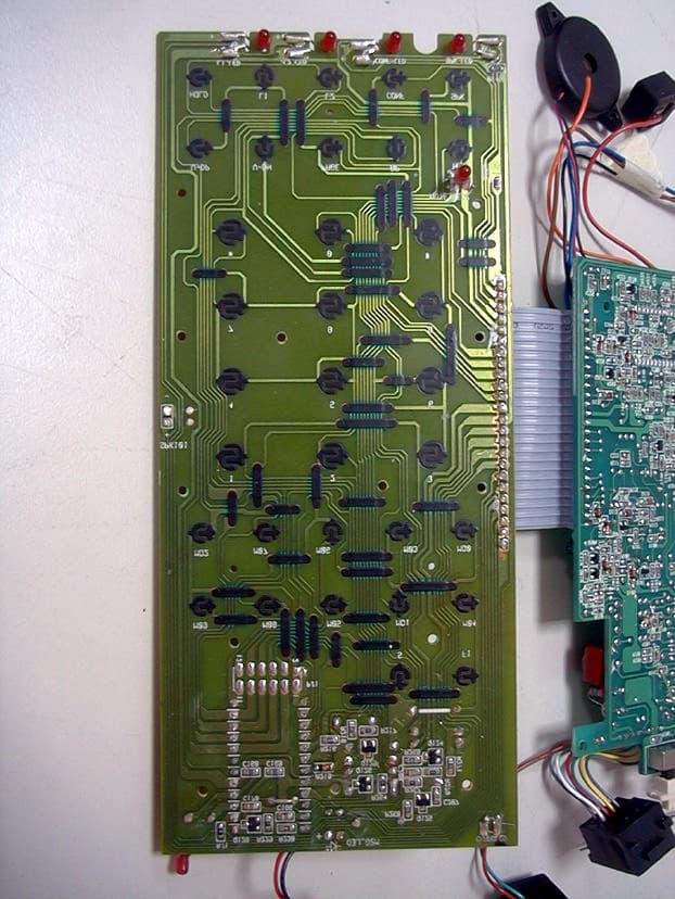
DXACL2910
Sep 11, 20002 Line 900MHz Cordless Speakerphone Telephone
Equipment Class
ETS - Part 15 Cordless Telephone System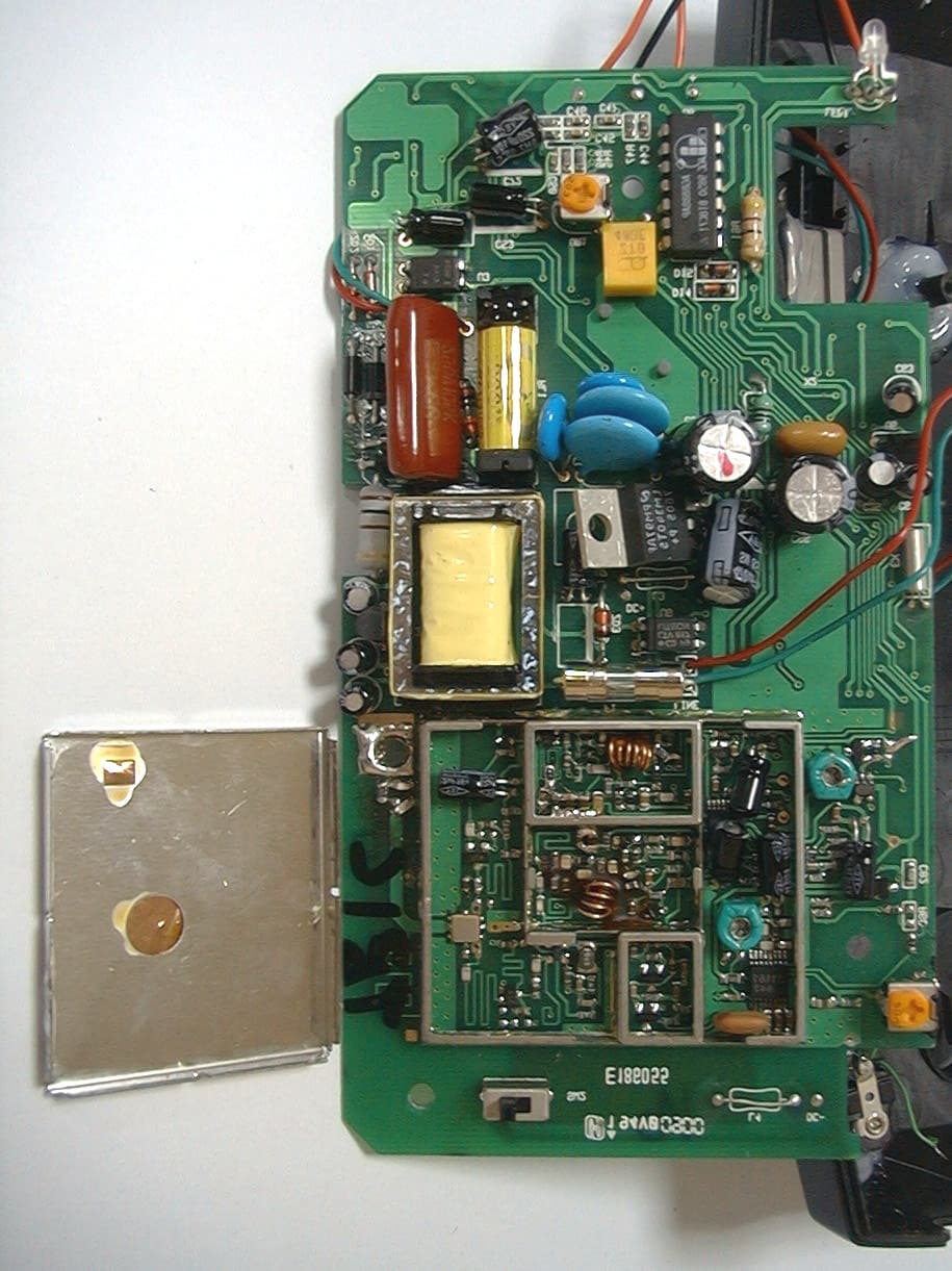
DXATR1C
May 09, 2000900 MHz Cordless Phone
Equipment Class
DXX - Part 15 Low Power Communication Device Transmitter