DYDWT3125Windows-Based Terminal
Wyse Technology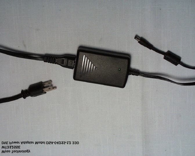
Click to zoom
Application Details
- Equipment Class
- JBP - Part 15 Class B Computing Device Peripheral
- Date of Grant
- Jul 30, 2002
- Application Purpose
- Original Equipment
- Date of Application
- Jul 30, 2002
- Equipment Note
- Windows-Based Terminal
- Company
- Wyse Technology
- Country
- United States
Documents & Files
Document Text
Text extracted from the exhibit documents filed with the FCC. Open a document above to read the original.
Users Manual
Winterm ™ Model 3125SE WBT Quick-Start Guide ➊ Connect – Caution: Improper connection, mounting, or use of this product could result in component failure and/or flash memory corruption. Read the following caution statements before setting up and operating the terminal. Cautions: Setup • Do not connect power until all other connections are made. Connecting or disconnecting components or devices on the back panel when the terminal is receiving power can cause power surges and damage the terminal. (USB ports are hot-swappable.) • Do not force a connector into its socket. If any undue resistance is encountered, ensure that the connector is correctly oriented to the receptacle. Orientation and Venting • Mount the terminal only as shown above. Improper orientation (such as component side down, where the back panel’s symbols are upside down) could inhibit the dissipation of heat from the terminal and damage it. • Allow sufficient space around the terminal for ventilation; do not place the terminal in any enclosure that restricts airflow around the terminal; do not place any objects on the terminal. Product environmental specifications are available through Wyse’s Web site at http://www.wyse.com/products/winterm/products.htm . Power Sources • To ensure regulatory compliance, use only the power supply included in the shipping box, or a Wyse-approved equivalent, with the terminal. Also, the noise suppressor (ferrite bead) included in the box with the terminal must be installed on the network cable as described in the accompanying instructions. Refer to the regulatory notices in the terminal’s on-line documentation at http://www.wyse.com/products/winterm/ quickstart/3000.htm. • To prevent accidental loss of power, brown out, and spikes which could damage the terminal, avoid connecting it to any form of switching device (including power strips) or hard resetting the terminal by holding down the power button. • When turning off the terminal, be sure to perform a complete shutdown (via the user interface or power button); do not disconnect the power cord, shut off power at a circuit breaker, etc., to turn off the terminal. *Supplied for U.S.A.; in other locales, check package contents or contact your Wyse reseller. 883752-01 Rev. A July 2002 Printed in U.S.A. Wyse Technology Inc. 3471 North First Street San Jose, CA 95134-1801 U.S.A. ©2002 Wyse Technology Inc. All rights reserved. 1. For a listing of recommended peripherals visit http://www.wyse.com/serviceandsupport/support/winterm/peripherals/3000peripheral.htm. ➋ Turn On – Wait until the initialization sequence is completed (amber light goes off) before pressing the power button. Important: By unpacking and using the terminal, you agree to be bound by the license agreements in the users and administrators guides. See those agreements for specific details at http://www.wyse.com/products/winterm/quickstart/ 3000.htm. ➌ Configure – Setup is quick and simple... The logo will appear on the screen, followed by: • The Setup Wizard, if it is the first time that you have turned on your terminal. • The Winterm Connection Manager dialog box, if the Setup Wizard has been completed. ➍ Help – Need more information or upgrades/accessories? http://www.wyse.com/products/winterm/quickstart/3000.htm Need more information on Wyse Rapport, the remote management software that comes with this terminal, or Wyse’s automated warranty registration † process? http://www.wyse.com/bundle † Register within 90 days to get 2 years’ extended warranty at no cost. Model 3125SE Back Panel Connectors IconConnectorDescription HeadphonesAudio output jack for headphones or powered speakers USB port (3)USB device connection VideoMonitor interface Network (LAN)Ethernet RJ45 connection, 10/100Base-T PowerPower module cable interface LockReceptacle for cable lock Parallel PortLocal printer output KeyboardPS/2-type keyboard interface MousePS/2-type mouse interface Serial Port 1 Serial device connection Serial Port 1 Serial device connection
Block Diagram
WT3125LE System Functional Block Diagram: 27 MHz 32.768KHz PS/2 PAL 16V8 KEYBOARD MOUSE PCI Video Conn. Vide o O/P 0- 128MB NAND FLAS H 32/64/128MB SDRAM (onboard) Bank 0 0- 128MB NAND FLASH 0-256MB IDE NAND MODULE USB Conn. 33 MHz 33 MHz 33 MHz ICS 9912 Geode SC2200 System Controller IDE 25 MHz NOR FLASH 10/100 Base-T NETWORK DP83815 LM4546 Codec BUF AUDI AC’97 USB Conn. USB Conn. Daughterboard Conn. PC87360 Super I/O IEEE1284 conn LPC EIA232E XCVRs Serial 1 conn Serial 2 conn 33 MHz 33 MHz
Cover Letter(s)
July 30, 2002 To: Mike Kuo Compliance Certification Services 561F Monterey Road Morgan Hill, CA 95037 Subject: FCC Part 15 Class B approval of our Windows-based Terminal model WT3125SE Dear Mr. Kuo: We would like to submit our new Windows-based Terminal model WT3125SE to obtain FCC part 15 class B approval under FCC ID DYDWT3125. The attached manual is being revised to include this model designation. The functionality of this model is similar to our approved model WT3200LE (DYDWT3200), except we have added a serial port and a parallel port and a single chip solution 266 MHz CPU. The logic board and chassis have been modified to accommodate these changes. With this letter, I have provided all the necessary documentation electronically and attached the radiated and conducted setup drawings. All the test equipment information has been included as part of the radiated and conducted test report. Equipment List for the Radiated Measurement test: Support and Test Equipment: See Radiated Measurement data sheet Equip me nt List for the Co nd ucted Meas ure me nt test: Support Equipment: HP PC Model: HP Brio PC (DOC) HP Serial Printer (FCC ID DS16XU2225) HP Parallel Printer (DOC) HP Monitor (DOC) Test Equipment: HP Spectrum Analyzer Model 85680B (RES BW: 30 KHz-100KHz, VBW: 10KHz- 30KHz) HP QP Adaptor Model 85650A If you have any questions or need additional information, please contact me at 408.473.2458 (voice), 408.473.2245 (fax), or jnguyen@w yse.com (email). Sincerely Yours, Jimmy Nguye n Regulator y E ngi neering Ma na ger Mo use FCC ID: JNZ2012 Mo use FCC ID: DZL211029 TEST SETUP FOR CONDUCTED MEASUREMENT Mo use Keyboard FCC ID: DOC Mo use Mo use FCC ID JNZ211360 SerialPrinter Parallel Printer 812C FCC ID: DOC EUT Modem FCC ID: DOC Keyboard FCC ID: DOC 2225D DS16XU2225 PowerSupply 19" Monitor FCC ID: DOC HPBrioFCCID:DOC LAN Cable Mo use FCC ID: JNZ2012 March 13, 2000 SerialPrinter Parallel Printer TEST SETUP FOR RADIATED MEASUREMENT 812C FCC ID: DOC Mo use Keyboard FCC ID: DOC EUT 21" Monitor FCC ID: DOC Mo use 2225D DS16XU2225 Mo use FCC ID JNZ211360 Headset &Microphone PowerSupply Modem FCC ID: DOC
Test Report
July 29, 2003 WYSE Technology FCC 3M Class B Test Record for Window Based Terminal Model Number: WT3125SE Tests performed by WYSE Technology 3471 N. First Street, San Jose, CA Test completed: July 27, 2002 Test Engineer: Jimmy Nguyen July 29, 2002 1.0INTRODUCTION 1.1 Scope This record is intended to document conformance with the EMC Directive (89/336/EEC) and details the results of testing performed on July 27, 2002 on the model WT3125SE . 1.2 Purpose Testing was performed to evaluate the emissions performance of the WT3125SE with respect to FCC 3m Class B . 1.3 Summary The Windows Terminal WT3125SE was found to be compliant to FCC 3m Class B Emission Requirements. 1.4 Testing Requirements Testing was performed using procedures and criteria contained in FCC 3m . 2.0TEST ENVIRONMENT 2.1 Test Sample Description WT3125SE is designed to communicate with a host system via Twiste d Pair LAN interface on NT Windows Server. Test Software The software used during the test was a continuous loop batch file on Windows NT station. The program creates an entire page of “H”’s and writes the entire page to the screen, and it also prints to the serial and parallel devices as used in the test setup. The cables were moved around to find the maximum emission from the EUT. 2.2 Test Facilities 2.2.1 Emissions Test Site Radiated emissions testing was performed in a 3m Semi-Anechoic Chamber. The description of the 3m Chambe r is filed at the WYSE Regulatory Engineering Department. The Chamber is located at 3471 N. First Street, San Jose, California, USA. Conducted emission testing was performed inside a shielded enclosure ( Screen Room ) in the WYSE RFI laboratory. The description of the screen room is filed at WYSE Regulatory Engineering Department. The Screen Room is located at 3471 N. First Street, San Jose, California, USA. July 29, 2002 2.3 Test Equipment The following are the list of equipment used during the radiation and conducted testing. Radiated: HP Receiver model 85460A (RES BW: 30 KHz-100KHz, VBW: 10KHz – 30KHz) Conducted: HP 85650A Quasi-Peak Adapter HP 85680B Spectrum Analyzer (RES BW: 30KHz –100KHz, VBW: 10KHz – 30KHz) SETUP: In accordance with WYSE Technology test procedure. PROCEDURE: Biconilog antenna w as used for frequency range 30MHz - 2 GHz. The frequency range w as checked for signals strength. The antenna w as then raised and low ered for final maximization. The frequency range w as checked with antennas in the horizontal and vertical polarization. 3.0TEST RESULTS 3.1 Test Description CISPR Publication 22:1997 , limits and methods of measurements of radio interface of information technology equipment, was the guiding document for the test. The product’s radiated emissions from 30 MHz to 2000 MHz and its power mains conducted emissions from 150 KHz to 30 MHz were measured. 3.2 Test Configuration The EUT was configured with a typical mix of available peripherals which fully configured all types of communications ports of the EUT and exercised it in a typical manner. 3.3 Test Procedure For radiated emissions testing, the equipment is installed on a 0.8 meter high non-conductive turntable 3 meters from the receiving antenna mast. The EUT is fully exercised during the test to maximize emissions. The receiving antenna is scanned over the height range of 1 to 4 meters is both polarities and the turntable is rotated with emissions level observed at each frequency. During the process the equipment configuration is also modified by moving the interconnecting cables to find the typical configuration that maximizes emissions at each frequency. The frequency range from 30 MHz to 2000 MHz is explored. Measurement data is compared to Class B limit. July 29, 2002 For conducted emissions testing, the equipment is moved to a 0.8 meter high platform and the EUT and configurations equipment are powered from a different LISNs. Both sides of the AC line are measured and the results compared to the Class B limit. 3.4 Test Results A comparison of the measured data with the Class B limit of FCC 3m shows that Windows Terminal WT3125SE was 2.79 dB below the limits at the worst case frequency of 399.93 MHz in a Horizontal Polarization. 3.5 Product Specification Model: WT3125SE (Logic Board P/N 961416-00 Rev 6) Clock Circuit: U8 = ICS9112-16, P/N 205572-50 (1:5 PLL zero-delay clock buffer) Filters: 33 MHz CLK Lines: R82-84 = 33 Ω , P/N 370513-13 (connected lines) RP9 = 51 Ω , P/N 371338-18 (terminated lines) U1 = SC2200-266, P/N 200069-51 Filters: 33 MHz CLK Lines: RP8 = 33 Ω , P/N 371338-02 Power Filters U1 = SC2200-266, P/N 200069-51 CRT Filter: L20 = 330 Ω bead, P/N 400044-06 C420 = 22uF, P/N 310226-02 C421 = 1uF, P/N 320343-25 C422, C423, C424 = 0.1 μ F, P/N 320334-37 PLL3 Fi l ter : L21, L22 = 330 Ω bead, P/N 400044-06 R58 = 10 Ω , P/N 370513-01 C425 = 10uF, P/N 310224-01 C426, C427 = 0.1 μ F, P/N 320334-24 PLL2 Fi l ter : L23, L24 = 330 Ω bead, P/N 400044-06 R59 = 10 Ω , P/N 370513-01 C428 = 10uF, P/N 310224-01 C429, C430 = 0.1 μ F, P/N 320334-24 July 26, 2001 Vide o Circuit: U1 = SC2200 Filters: L2 = 0.47 μ H, P/N 410038-02; C4, C7 = 22pF, P/N 320347-21 L3 = 0.47 μ H, P/N 410038-02; C3, C6 = 22pF, P/N 320347-21 L4 = 0.47 μ H, P/N 410038-02; C2, C5 = 22pF, P/N 320347-21 Termination: R4, R5, R6 = 75 Ohm, P/N 370508-85 Audio Circuit: U11 = LM4546, P/N 205123-53 Power Filters: C411, C412, C413, C415 = 0.1 μ F, P/N 320347-21 C410, C414 = 10uF, P/N 310224-01 L18, L19 = 70 Ohm, P/N 400040-04 Clock Filters: R30, R31, R45 = 33 Ω , P/N 370513-13 Driving Transistor: Q7, Q8 = MMBT3904, P/N 270010-50 Ne twork: U2 = DP83815, P/N 205127-50 Filters: R11, R12 = 49.9 Ohm, P/N 370508-68 C597 = 0.1 μ F, P/N 320347-21 J4 = RJ45 Connector w/ transformer built in, P/N 563680-01 Filters: C19, C20 = 0.1 μ F, P/N 320347-21 R9, R10 = 54.9 Ohm, P/N 370508-72 C56, C57 = 15pF, 320347-17 Q uie t G round: L29 = 2T 6-hole ferrite, P/N 400022-03 Radiated Emission Test 3m Semi Anechoic Chamber WYSE Technology Inc. 3471 North 1st Street San Jo…
Text truncated - open the document above for the full version.
Contact Information
Applicant
Benton Ng(Regulatory Engineer)
Test Firm
Wyse TechnologyJames Nguyen
Technical Specifications
| # | Rule Parts | Frequency Range | Power Output |
|---|---|---|---|
| 1 | 15B | - | - |
Other Applications from Wyse Technology
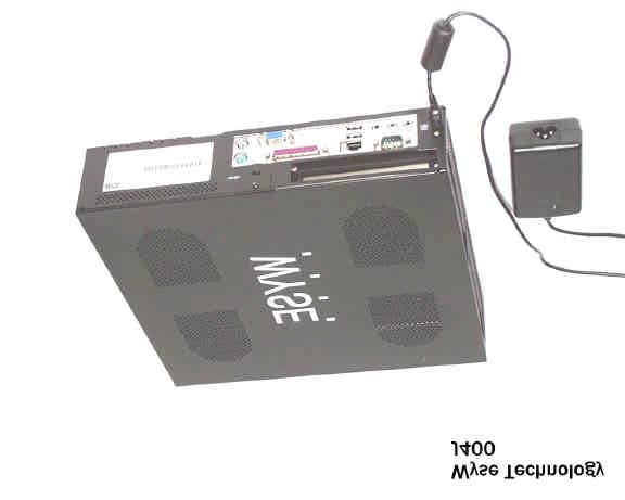
DYDJ400
May 27, 2003Windows-based Terminal
Equipment Class
JBC - Part 15 Class B Computing Device/Personal Computer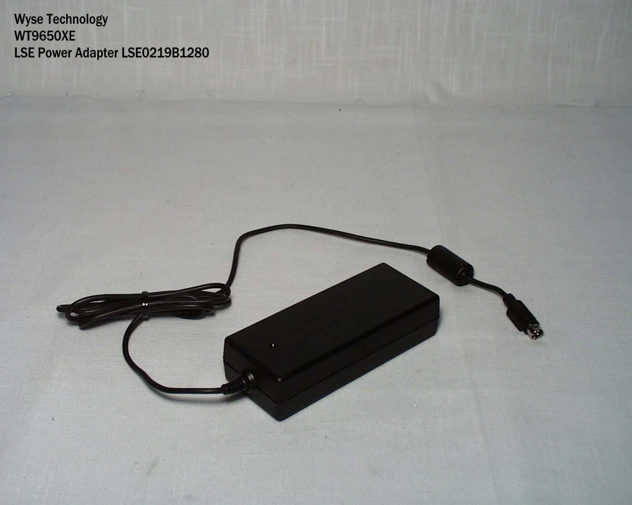
DYDWT9650
Apr 27, 2003Windows-Based Terminal
Equipment Class
JBP - Part 15 Class B Computing Device Peripheral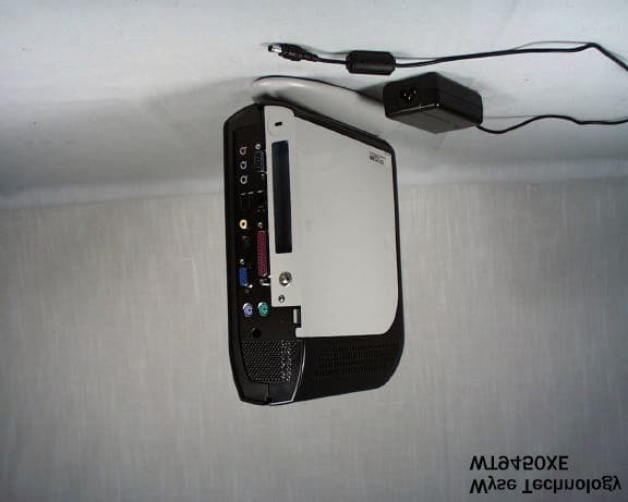
DYDWT9450
Oct 03, 2002Windows-Based Terminal
Equipment Class
JBC - Part 15 Class B Computing Device/Personal Computer
DYDWT8440
Aug 16, 2001Windows-Based Terminal
Equipment Class
JBC - Part 15 Class B Computing Device/Personal Computer
DYDWT3235
Jun 21, 2001Window Based Terminal
Equipment Class
JBP - Part 15 Class B Computing Device Peripheral