DYDWT3235Window Based Terminal
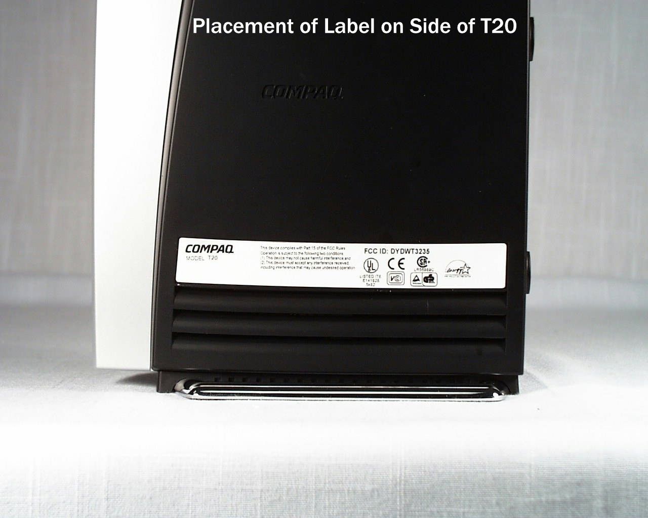
Wyse Technology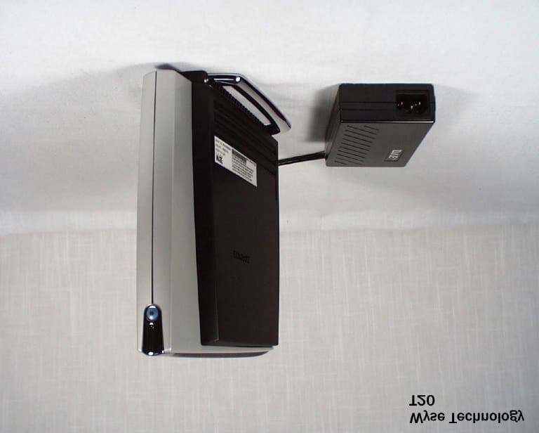
Click to zoom
Application Details
- Equipment Class
- JBP - Part 15 Class B Computing Device Peripheral
- Date of Grant
- Jun 21, 2001
- Application Purpose
- Original Equipment
- Date of Application
- Jun 21, 2001
- Equipment Note
- Window Based Terminal
- Company
- Wyse Technology
- Country
- United States
Documents & Files
Document Text
Text extracted from the exhibit documents filed with the FCC. Open a document above to read the original.
Users Manual
CompaqEvoT20 and Compaq T1010 NT Embedded Terminals Quick Reference Guide ii Copyright Notice The information in this document is subject to change. COMPAQ COMPUTER CORPORATION SHALL NOT BE LIABLE FOR TECHNICAL OR EDITORIAL ERRORS OR OMISSIONS CONTAINED HEREIN; NOR FOR INCIDENTAL OR CONSEQUENTIAL DAMAGES RESULTING FROM THE FURNISHING, PERFORMANCE, OR USE OF THIS MATERIAL. This document contains information protected by copyright. No part of this document may be photocopied or reproduced in any form without prior written consent from Compaq Computer Corporation. © 2001 Compaq Computer Corporation. All rights reserved. Created in the United States. This manual and the software and firmware described in it are copyrighted. You may not reproduce, transmit, transcribe, store in a retrieval system, or translate into any language or computer language, in any form or by any means, electronic, mechanical, magnetic, optical, chemical, manual or otherwise, any part of this publication without express written permission. Trademarks COMPAQ and the Compaq logo are registered in the U.S. Patent and Trademark office.Evois a trademark of Compaq Information Technologies Group, L.P. in the United States and other countries. ICA is a registered trademark and MetaFrame is a trademark of Citrix Systems Inc. Microsoft, Windows, are registered trademarks of Microsoft Corporation. Product names mentioned herein may be trademarks and/or registered trademarks of their respective companies. The Energy Star emblem does not represent endorsement of any product or service. Specifications subject to change without notice. Restricted Rights Legend Use, duplication, or disclosure by the Government is subject to restrictions as set forth in subparagraph (c)(1)(ii) of the Rights in Technical Data and Computer Software clause at DFARS 252.227-7013 iii Patents The Compaq product(s) described herein is (are) covered by U.S. Patent No. 5,918,039 and other patents pending. iv FCC Statement This equipment has been tested and found to comply with the limits for either Class A or Class B digital devices (refer to “Terminal Requirements Compliance”) pursuant to Part 15 of the FCC Rules. These limits are designed to provide reasonable protection against harmful interference in a residential installation. This equipment generates, uses, and can radiate radio frequency energy and, if not installed and used in accordance with the instructions, may cause harmful interference to radio communications. However, there is no guarantee that interference will not occur in a particular installation. If this equipment does cause harmful interference to radio or television reception, which can be determined by turning the equipment off and on, the user is encouraged to try to correct the interference by one or more of the following measures: • Reorient or relocate the receiving antenna. • Increase the separation between the equipment and the receiver. • Connect the equipment into an outlet on a circuit different from that to which the receiver is connected. • Consult the dealer or an experienced radio/TV technician for help. Caution Changes or modifications not covered in this manual must be approved in writing by the manufacturer’s Regulatory Engineering department. Changes or modifications made without written approval may void the user’s authority to operate the equipment. Terminal Requirements Compliance The T1010 and Evo T20 terminals meet Class B requirements. Canadian DOC Notices Class A This digital apparatus does not exceed the Class A limits for radio noise emissions from digital apparatus set out in the Radio Interference Regulations of the Canadian Department of Communications. Le présent appareil numérique n’émet pas de bruits radioélectriques dépassant les limites applicables aux appareils numériques de la classe A prescrites dans le Réglement sur le brouillage radioélectrique édicté par le Ministère des Communications du Canada. v Class B This digital apparatus does not exceed the Class B limits for radio noise emissions from digital apparatus set out in the Radio Interference Regulations of the Canadian Department of Communications. Le présent appareil numérique n’émet pas de bruits radioélectriques dépassant les limites applicables aux appareils numériques de la classe B prescrites dans le Réglement sur le brouillage radioélectrique édicté par le Ministère des Communications du Canada. IEC/EN Notice This product conforms to the requirements of IEC950 and EN60950. This product conforms to requirements of EN55022 for Class A equipment or EN55022 for Class B equipment (refer to “Terminal Requirements Compliance”). Cable Notice The use of shielded I/O cables is required when connecting this equipment to any and all optional peripheral or host devices. Failure to do so may cause interference and violate FCC and international regulations for electromagnetic interference. vi Control No. 075B License Agreement YOU SHOULD CAREFULLY READ THE FOLLOWING TERMS AND CONDITIONS BEFORE USING THIS SOFTWARE (TOGETHER WITH ANY SUPPLIED DOCUMENTATION, HEREAFTER "SOFTWARE"), WHICH IS OWNED BY THE MANUFACTURER OR ITS LICENSORS. USING THIS SOFTWARE INDICATES YOUR ACCEPTANCE OF THE FOLLOWING TERMS AND CONDITIONS. THE MANUFACTURER’S LICENSORS ARE INTENDED THIRD-PARTY BENEFICIARIES UNDER THIS AGREEMENT. Grant You may use the Software in or in conjunction with Your manufacturer-produced hardware (Terminal). You have the right to use this Software by loading it onto a computer containing the capability of transferring the Software (in whole or in part) to the manufacturer-produced hardware. You may use the Software in this fashion as many times as necessary, so long as such use is always in conjunction with the manufacturer-produced Terminal. You may transfer ownership of the Terminal and equipment, including the right to use the Software to another party so long as that party agrees to accept these terms and conditions. YOU MAY NOT USE, COPY, MODIFY, TRANSL…
Text truncated - open the document above for the full version.
Block Diagram
System Functional Block Diagram: 14.318 MHz 14.318 MHz 24 MHz 25 MHz 32.768 KHz 0-256MB SDRAM (SODIMM) Banks 2/3 TUSB2046B Hub Chi p PS/2 Geode GX1 System Controller NOR FLASH PAL 16V8 NETWORK DP83815 CS5530A Companion Chip LM4546 Codec BUF KEYBOARD MOUSE 10/100 Base-T AUDI ISA PCI Video Conn. Vide o O/P 0- 128MB NAND FLAS H 0/32/64/128MB SDRAM (onboard) Bank 0 0- 128MB NAND FLASH 0- 128MB SMART MEDIA USB Conn. REAL - TIME CLOCK 33 MHz 48 MHz MK 1492 CLOCK GENERATOR
Cover Letter(s)
RE: Wyse Technology, FCC ID:DYDWT3235, Assessment no:AN01T1364From: Suzanne Thomas [[email protected]] Sent: Thursday, June 21, 2001 4:28 PM To: Mike Kuo Cc: Benton Ng Subject: RE: Wyse Technology, FCC ID:DYDWT3235, Assessment no:AN01T1364 Hi, Here is the revised block diagram. Let us know if you have any questions. Best Regards, Suzanne Thomas (408) 473-2075 -----Original Message----- From: Mike Kuo [mailto:[email protected]] Sent: Tuesday, June 19, 2001 4:44 PM To: Suzanne Thomas; Mike Kuo Cc: Benton Ng Subject: RE: Wyse Technology, FCC ID:DYDWT3235, Assessment no:AN01T1364 Dear Suzanne: One more question: Please indicate all local osc. on the functional block diagram. Best Regards Mike Kuo -----Original Message----- From: Suzanne Thomas [mailto:[email protected]] Sent: Tuesday, June 19, 2001 3:48 PM To: Mike Kuo Cc: Benton Ng Subject: RE: Wyse Technology, FCC ID:DYDWT3235, Assessment no:AN01T1364 Dear Mike, The conducted measurement test was repeated. I have revised the cover letter and conducted test setup drawing by changing the monitor to a 19" HP monitor. I've uploaded this letter and test setup drawing, along with the new conducted data, front and back photos of the conducted test, three photos of the interior of the power adapter, and photo of the solder side of the main board. Please contact us if you have any questions. Best Regards, Suzanne Thomas Regulatory Engineering Wyse Technology (408) 473-2075 -----Original Message----- From: Mike Kuo [mailto:[email protected]] Sent: Friday, June 15, 2001 6:55 PM To: Benton Ng; Mike Kuo Cc: Suzanne Thomas Subject: RE: Wyse Technology, FCC ID:DYDWT3235, Assessment no:AN01T1364 Dear Benton" Question #1:Even the power adapter is from different vendor which has UL/CE marking on the product. This external power adapter is part of EUT so internal photos are required. Question #2:Acknowledged Question #3:The peripherals used during final compliance tests shall be un-modified and readily available from retail stores. The printer that you used has FCC DoC / FCC ID number compliance information on it. If you modify the compliance product, then you are the responsible party for product compliance. Because you have no control on which printer that the end-user will be used to connect to the EUT, the modification you made on the printer to reduce the emission level is not acceptable. Please redo Conducted emission tests with un- modified peripherals. Best Regards Mike Kuo / TCB Certifier -----Original Message----- From: Benton Ng [mailto:[email protected]] Sent: Friday, June 15, 2001 6:09 PM To: Mike Kuo Cc: Suzanne Thomas Subject: RE: Wyse Technology, FCC ID:DYDWT3235, Assessment no:AN01T1364 -----Original Message----- From: Mike Kuo [SMTP:[email protected]] Sent: Friday, June 15, 2001 11:40 AM To: Benton Ng; Jimmy Nguyen Cc: Mike Kuo Subject: RE: Wyse Technology, FCC ID:DYDWT3235, Assessment no:AN01T1364 Hi Mike, Thank you for your prompt attention for our application. Here's our reply to your "Questions" below" #1: We purchase external power adapter from the out side vendors. These power adapter has already approved for Safety and CE. We you still think there a need to include external power adapter board in the report. Please let me know. There no problem. #2: I will go ahead and provide you with the solder side of the main board and send it to you. #3: We regard the printer as a peripheral equipment only. We do not ship the printer with our product; and we have no control of what the customers use for their printers. Adding the ferrite on the power adapter for the printer eliminates the possibility of adding the emission to the true measurement of the EUT (our product). But if you still think that it is not permitted, we can do another conducted test, and send you a new set of data. There's no problem, excepted that it may delay the processing time for our application. Please call or email me with your reply as soon as you can. Thank you very much for you quick attention. Benton Ng Regulatory Engineer (408)473-1937 [email protected] -----Original Message----- From: CERTADM Sent: Friday, June 15, 2001 11:38 AM To: 'wyse.com' Cc: Mike Kuo Subject: Wyse Technology, FCC ID:DYDWT3235, Assessment no:AN01T1364 Notice_content ------------- Question #1: Internal Photos: Please provide Pictures for component and solder sides of power supply. Question #2: Internal Photos: Please provide photos for Solder side of Main Board. Question #3: Power cord for Printer: As indicated in the test setup photos, the power cord used during the radiated emission does not have ferrite core loaded on the power cord. However, during the conducted emission tests, the power cord for printer was modified with ferrite core added to the cable. Please explain. Best Regards Mike Kuo / TCB Certifier The items indicated above must be submitted before processing can continue on the above referenced application. Failure to provide the requested information within 60 days of the original e-mail date may result in application dismissal and forfeiture of the filing fee. Also, please note that partial responses increase processing time and should not be submitted. Any questions about the content of this correspondence should be directed to the e-mail address listed below the name of the sender.
Test Report
June 6, 2001 WYSE Technology EN 55022-B Test Record for Window Based Terminal Model Number: T20 Tests performed by WYSE Technology 3471 N. First Street, San Jose, CA Test completed: May 30, 2001 Test Engineer: Harinder Phul Approved by: Jimmy Nguyen June 6, 2001 1.0INTRODUCTION 1.1 Scope This record is intended to document conformance with the EMC Directive (89/336/EEC) and details the results of testing performed on June 6, 2001 on the model T20 . 1.2 Purpose Testing was performed to evaluate the emissions performance of the T20 with respect to EN 55022 Class B . 1.3 Summary The Windows Terminal T20 was found to be compliant to EN 55022 Class B Emission Requirements. 1.4 Testing Requirements Testing was performed using procedures and criteria contained in EN 55022 . 2.0TEST ENVIRONMENT 2.1 Test Sample Description T20 is designed to communicate with a host system via Twiste d Pair LAN interface on NT Windows Server. Test Software The software used during the test was a continuous loop batch file on Windows NT station. The program creates an entire page of “H”’s and writes the entire page to the screen, and it also prints to the serial and parallel devices as used in the test setup. The cables were moved around to find the maximum emission from the EUT. 2.2 Test Facilities 2.2.1 Emissions Test Site Radiated emissions testing was performed on a weather protected Open Area Test Site. The description of OATS is filed at the WYSE Regulatory Engineering Department. The OATS is located at 3471 N. First Street, San Jose, California, USA. Conducted emission testing was performed inside a shielded enclosure ( Screen Room ) in the WYSE RFI laboratory. The description of the screen room is filed at WYSE Regulatory Engineering Department. The Screen Room is located at 3471 N. First Street, San Jose, California, USA. June 6, 2001 2.3 Test Equipment The following are the list of equipment used during the radiation and conducted testing. Radiated: HP Receiver model 84560A (RES BW: 30 KHz-100KHz, VBW: 10KHz – 30KHz) Conducted: HP 85650A Quasi-Peak Adapter HP 8566B Spectrum Analyzer (RES BW: 30KHz –100KHz, VBW: 10KHz – 30KHz) SETUP: In accordance with WYSE Technology test procedure. PROCEDURE: Biconilog antenna w as used for frequency range 30MHz - 2 GHz. The frequency range w as checked for signals strength. The antenna was then raised and lowered for final maximization. The frequency range was checked with antennas in the horizontal and vertical polarization. 3.0TEST RESULTS 3.1 Test Description CISPR Publication 22:1997 , limits and methods of measurements of radio interface of information technology equipment, was the guiding document for the test. The product’s radiated emissions from 30 MHz to 1000 MHz and its power mains conducted emissions from 150 KHz to 30 MHz were measured. 3.2 Test Configuration The EUT was configured with a typical mix of available peripherals which fully configured all types of communications ports of the EUT and exercised it in a typical manner. 3.3 Test Procedure For radiated emissions testing, the equipment is installed on a 0.8 meter high non-conductive turntable 10 meters from the receiving antenna mast. The EUT is fully exercised during the test to maximize emissions. The receiving antenna is scanned over the height range of 1 to 4 meters is both polarities and the turntable is rotated with emissions level observed at each frequency. During the process the equipment configuration is also modified by moving the interconnecting cables to find the typical configuration that maximizes emissions at each frequency. The frequency range from 30 MHz to 1000 MHz is explored. Measurement data is compared to Class B limit. June 6, 2001 For conducted emissions testing the equipment is moved to a 0.8 meter high platform and the EUT and Configurations equipment are powered from a different LISNs. Both sides of the AC line are measured and the results compared to the Class B limit. 3.4 Test Results A comparison of the measured data with the Class B limit of CISPR shows that Windows Terminal T20 was 4.95 dB below the limits at the worst case frequency of 224.971365 MHz in a Vertical Polarization. 3.5 Product Specification Model: T20 (Logic Board P/N 961401-00, Rev. 3) Clock Circuit: U16 = MK1492-03, P/N 205565-50 Filters: 33 MHZ CLK Li ne: RP29 = 33 Ohm, P/N 371338-02; C45, C46, C47 = 15pF (not loaded) 14 MHZ CLK Li ne: R59 = 33 Ohm, P/N 370513-13; C44 = 15pF (not loaded) 48 MHZ CLK Li ne: R60 = 33 Ohm, P/N 370513-13; C43= 15pF(not loaded) 24 MHZ ( Audio) CLK Line: R61 = 33 Ohm, P/N 370513-13; C42= 15pF (not loaded) U1 = GX1-300, P/N 20064-55 Power Filter U2 = CS5530A, P/N 205122-52 Filters: R4 = 33 Ohm, P/N 370513-13; C2 = 15pF (not loaded) R5 = 33 Ohm, P/N 370513-13; C3 = 15pF (not loaded) L21 = 22 μ H, P/N 410032-09 L20 = 44MTL, P/N 400021-04 L22 = 43MTL, P/N 400021-01 RP 1-7 = 75 Ohm, P/N 371338-12 June 6, 2001 Vide o Circuit: U2 = CS5530A, P/N 205122-52 Filters: L1 = 0.47 μ H, P/N 410038-02; C7, C10 = 22pF, P/N 320313-21 L2 = 0.47 μ H, P/N 410038-02; C6, C9 = 22pF, P/N 320313-21 L3 = 0.47 μ H, P/N 410038-02; C5, C8 = 22pF, P/N 320313-21 Termination: R8, R9, R10 = 75 Ohm, P/N 370508-85 Audio Circuit: U14 = LM4546, P/N 205123-53 Filters: C431 = 0.1 μ F, P/N 320338-24 L25, L26 = 50 Ohm, P/N 400040-03 Driving Transistor: Q3, Q4 = MMBT3904, P/N 270010-50 Ne twork: U3 = DP83815, P/N 205127-51 Filters: R67, R68 = 49.9 Ohm, P/N 370508-68 J10 = RJ45 Connector w/ transformer built in, P/N 563680-01 Filters: C37, C38, C39 = .1 uF, P/N 320338-24 R65, R66 = 54.9 Ohm, P/N 370508-72 R67, R68 = 49.9 Ohm, P/N 370508-68 G round Jumpe r Se tting: R165, R166 = 0 Ohm, P/N 370514-99 Radiated Emission Test 10M OATS WYSE Technology Inc. 3471 North 1st Street San Jose Ca 95134 Test Description : EUT: T20 Serial No. 9GV1A500022 Part No. 902021-01 File No. 053001#3 Test Type: EN55022 EN55022 FCC-A { } FCC-B { X } CISPR-A { } CISPR-B { X } PASS: X FAIL: Debug: Frequency Peak DelLim-Pk QP DelLim-QP Angle Hgt …
Text truncated - open the document above for the full version.
Contact Information
Applicant
Benton Ng(Regulatory Engineer)
Test Firm
Wyse TechnologyJames Nguyen
Technical Specifications
| # | Rule Parts | Frequency Range | Power Output |
|---|---|---|---|
| 1 | 15B | - | - |
Other Applications from Wyse Technology
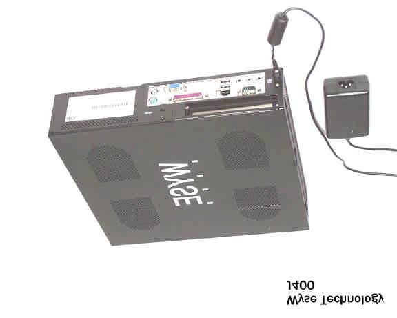
DYDJ400
May 27, 2003Windows-based Terminal
Equipment Class
JBC - Part 15 Class B Computing Device/Personal Computer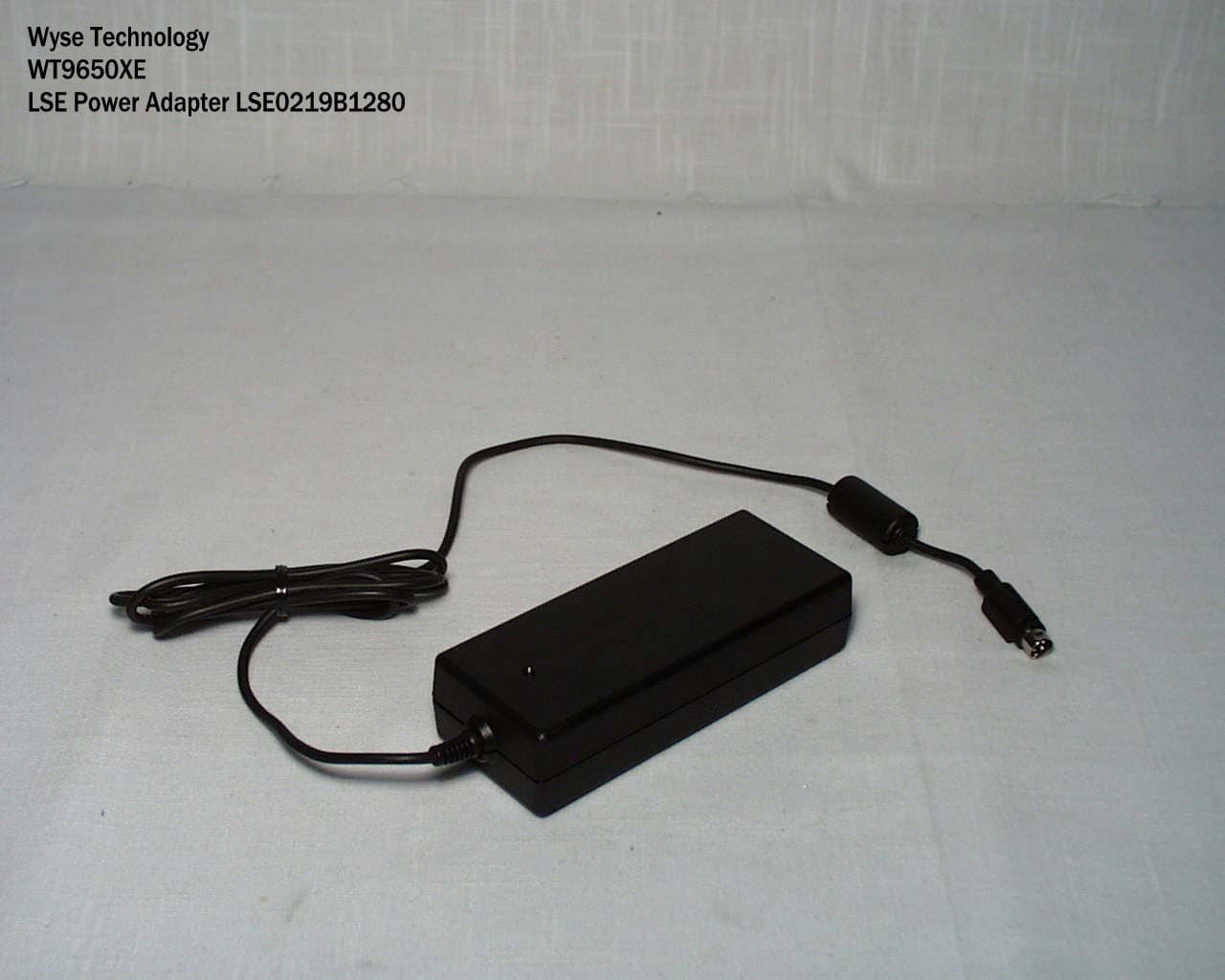
DYDWT9650
Apr 27, 2003Windows-Based Terminal
Equipment Class
JBP - Part 15 Class B Computing Device Peripheral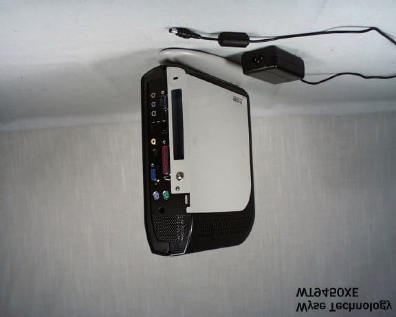
DYDWT9450
Oct 03, 2002Windows-Based Terminal
Equipment Class
JBC - Part 15 Class B Computing Device/Personal Computer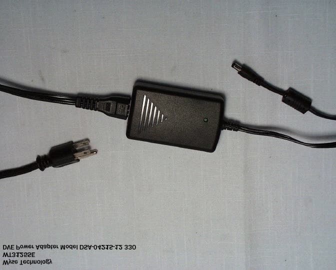
DYDWT3125
Jul 30, 2002Windows-Based Terminal
Equipment Class
JBP - Part 15 Class B Computing Device Peripheral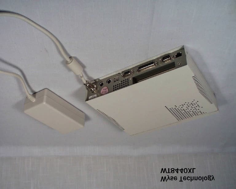
DYDWT8440
Aug 16, 2001Windows-Based Terminal
Equipment Class
JBC - Part 15 Class B Computing Device/Personal Computer