DYDWT3720
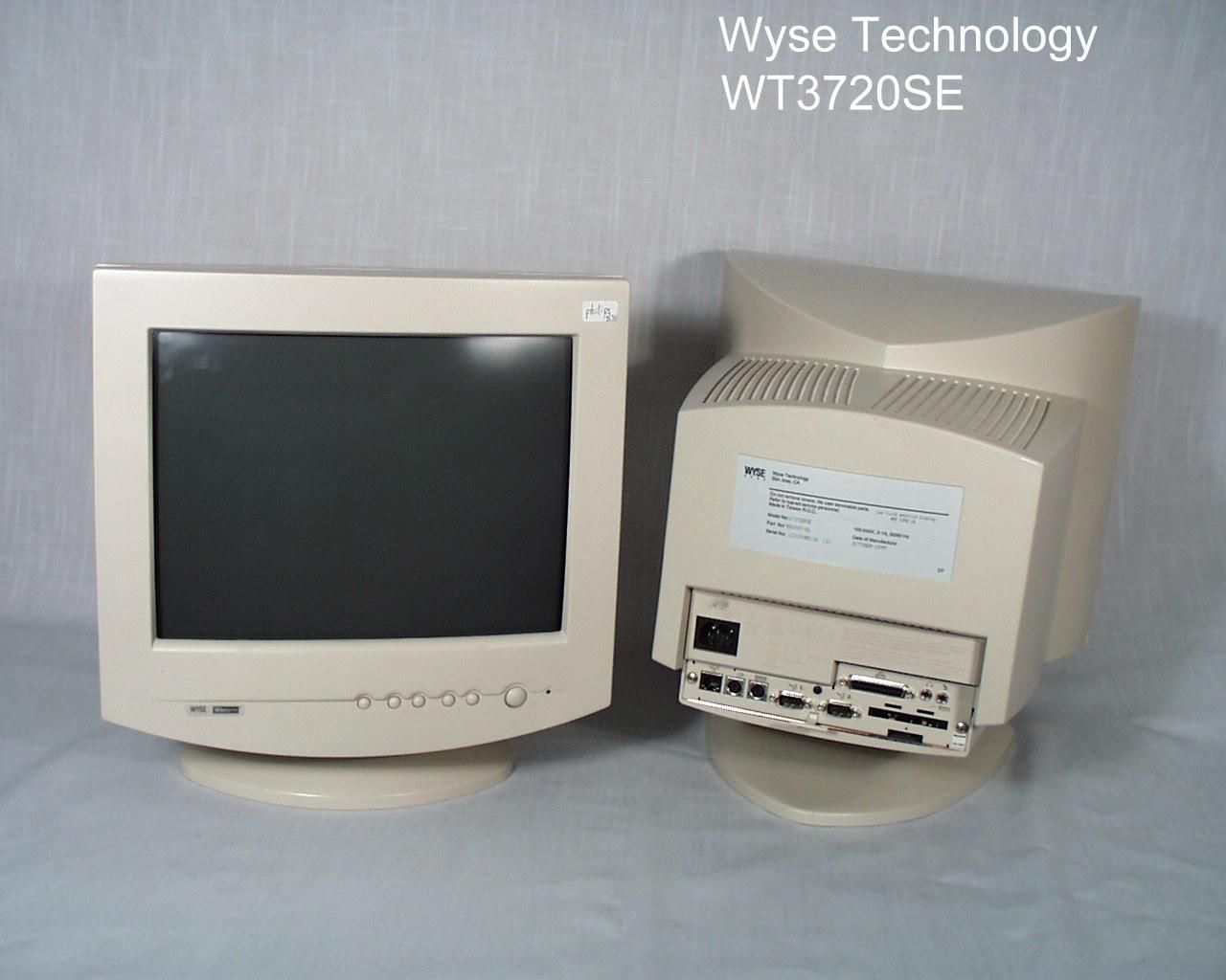
Wyse Technology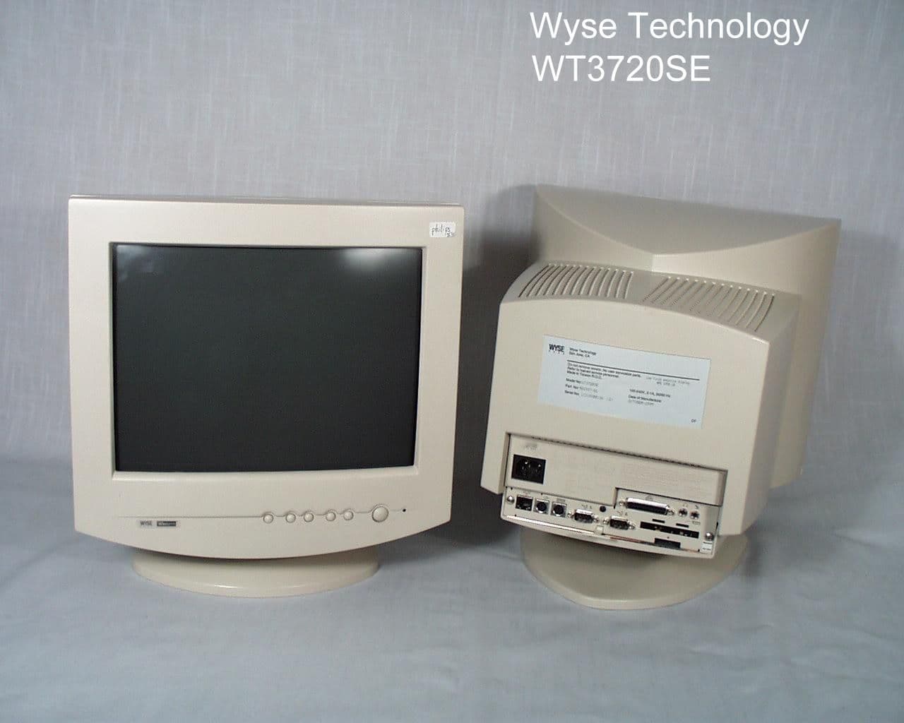
Click to zoom
Application Details
- Equipment Class
- JBP - Part 15 Class B Computing Device Peripheral
- Date of Grant
- Dec 27, 1999
- Application Purpose
- Original Equipment
- Date of Application
- Nov 10, 1999
- Company
- Wyse Technology
- Country
- United States
Documents & Files
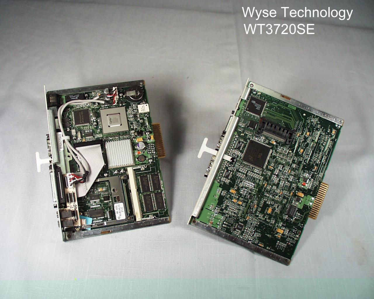
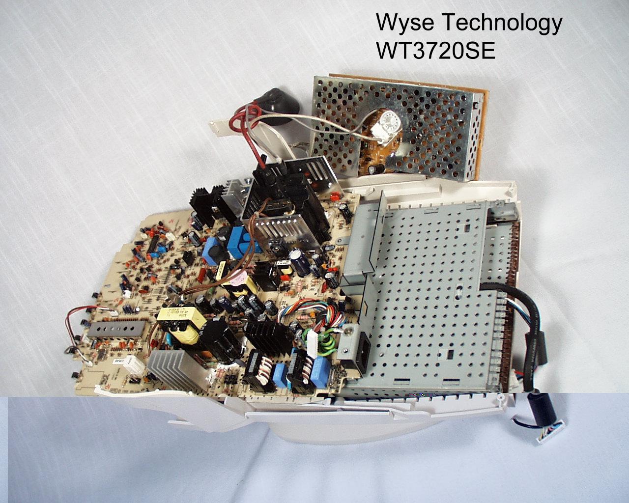
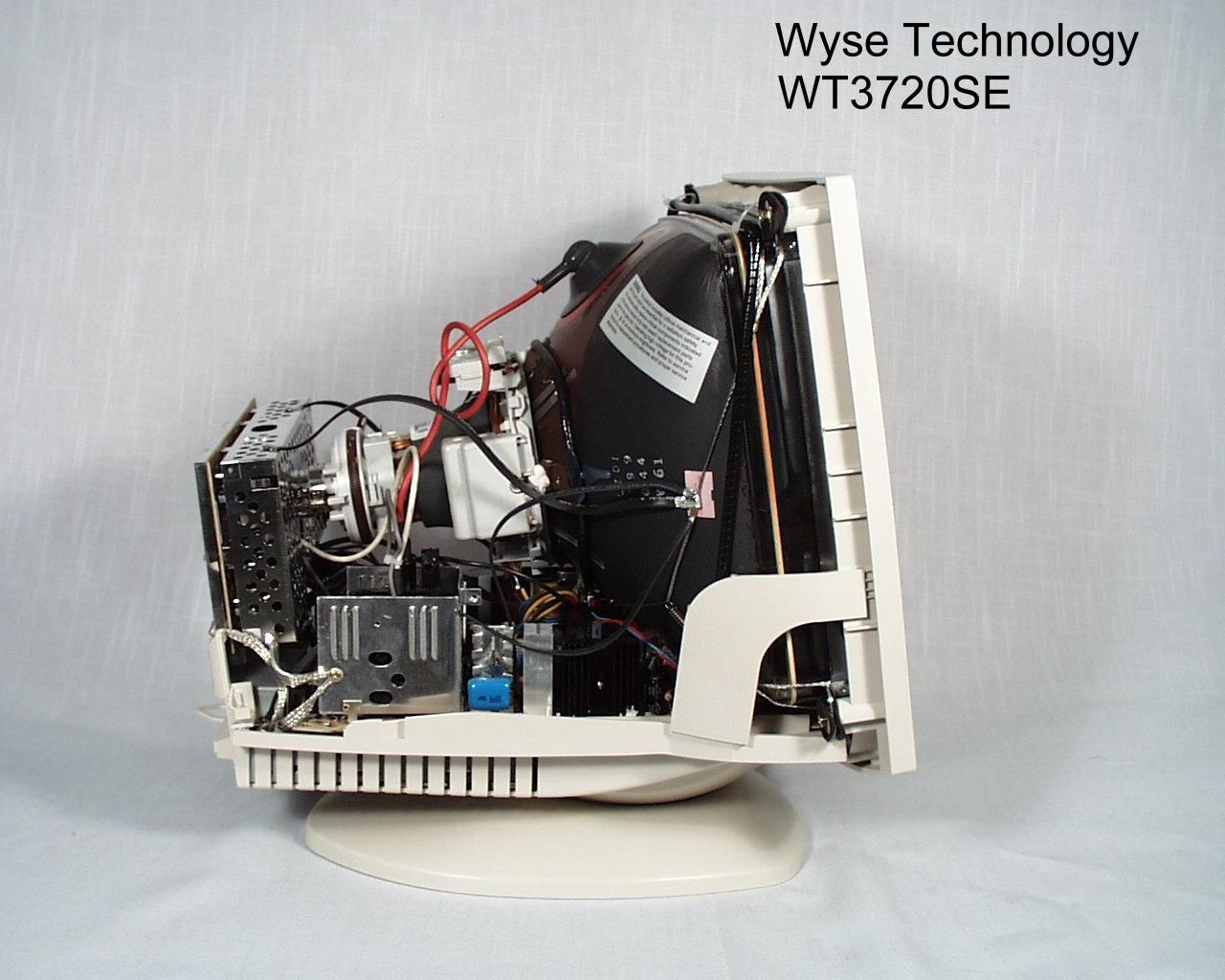
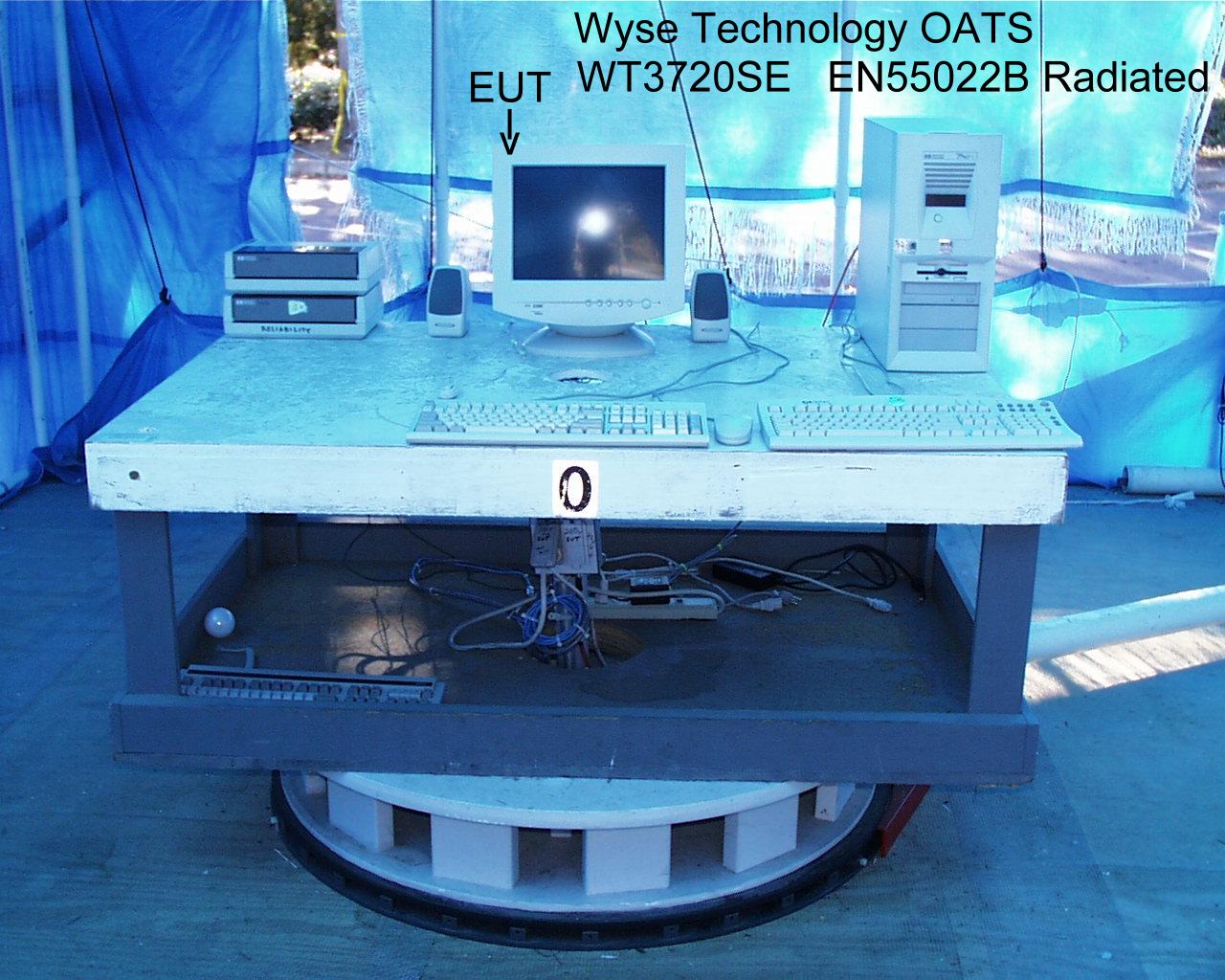
Document Text
Text extracted from the exhibit documents filed with the FCC. Open a document above to read the original.
Users Manual
Winterm 3000 Series Windows ® -based Terminal Reference Guide Winterm 3000 Series Windows ® -based Terminal Reference Guide 883590-08 Rev. A August 1999 Wyse Technology Inc. 3471 North First Street San Jose, CA 95134-1803 ii Copyright Notice © 1999 ALL RIGHTS RESERVED. This manual and the software and firmware described in it are copyrighted. You may not reproduce, transmit, transcribe, store in a retrieval system, or translate into any language or computer language, in any form or by any means, electronic, mechanical, magnetic, optical, chemical, manual or otherwise, any part of this publication without express written permission. Trademarks WYSE is a registered trademark and Winterm is a trademark of Wyse Technology Inc. ICA 3 is a registered trademark and MetaFrame is a trademark of Citrix Systems Inc. Microsoft and Windows are registered trademarks of Microsoft Corporation. All other products are trademarks and/or registered trademarks of their respective companies. The Energy Star emblem does not represent endorsement of any product or service. Specifications subject to change without notice. Restricted Rights Legend Use, duplication, or disclosure by the Government is subject to restrictions as set forth in subparagraph (c)(1)(ii) of the Rights in Technical Data and Computer Software clause at 252.227-7013. Ordering Information For availability, pricing, and ordering information in the United States and Canada, call 1-800-GET-WYSE (1-800-438-9973). In all other countries, contact your sales representative. Wyse Technology Inc. 3471 North First Street San Jose, CA 95134-1803 U.S.A. iii FCC Statement This equipment has been tested and found to comply with the limits for either Class A or Class B digital devices (refer to “Terminal Requirements Compliance”), pursuant to Part15 of the FCC Rules. These limits are designed to provide reasonable protection against harmful interference in a residential installation. This equipment generates, uses, and can radiate radio frequency energy and, if not installed and used in accordance with the instructions, may cause harmful interference to radio communications. However, there is no guarantee that interference will not occur in a particular installation. If this equipment does cause harmful interference to radio or television reception, which can be determined by turning the equipment off and on, the user is encouraged to try to correct the interference by one or more of the following measures: • Reorient or relocate the receiving antenna. • Increase the separation between the equipment and the receiver. • Connect the equipment to an outlet on a circuit different from that to which the receiver is connected. • Consult the dealer or an experienced radio/TV technician for help. Caution Changes or modifications not covered in this manual must be approved in writing by the manufacturer’s Regulatory Engineering department. Changes or modifications made without written approval may void the user’s authority to operate the equipment. Terminal Requirements Compliance Models 3315SE, 3320SE, 3350SE, 3515SE, 3715SE, and 3720SE terminals meet Class B requirements. iv Canadian DOC Notices Refer to the previous section, “Terminal Requirements Compliance,” to find out what model terminal each of the statements below refers to. Class A This digital apparatus does not exceed the Class A limits for radio noise emissions from digital apparatus set out in the Radio Interference Regulations of the Canadian Department of Communications. Le présent appareil numérique n’émet pas de bruits radioélectriques dépassant les limites applicables aux appareils numériques de la classe A prescrites dans le Réglement sur le brouillage radioélectrique édicté par le Ministère des Communications du Canada. Class B This digital apparatus does not exceed the Class B limits for radio noise emissions from digital apparatus set out in the Radio Interference Regulations of the Canadian Department of Communications. Le présent appareil numérique n’émet pas de bruits radioélectriques dépassant les limites applicables aux appareils numériques de la classe B prescrites dans le Réglement sur le brouillage radioélectrique édicté par le Ministère des Communications du Canada. IEC/EN Notice This product conforms to the requirements of IEC950 and EN60950. This product conforms to requirements of EN55022 for Class A equipment or EN55022 for Class B equipment (refer to “Terminal Requirements Compliance”). Cable Notice The use of shielded I/O cables is required when connecting this equipment to any and all optional peripheral or host devices. Failure to do so may cause interference and violate FCC and international regulations for electromagnetic interference. v Control No. 075B License Agreement YOU SHOULD CAREFULLY READ THE FOLLOWING TERMS AND CONDITIONS BEFORE USING THIS EQUIPMENT WHICH CONTAINS SOFTWARE IN A NON-VOLATILE FORMAT AND CERTAIN OTHER INTELLECTUAL PROPERTY (HEREAFTER “FIRMWARE”). USING THIS EQUIPMENT INDICATES YOUR ACCEPTANCE OF THE FOLLOWING TERMS AND CONDITIONS. Grant You may use the Firmware in or in conjunction with the Equipment as provided to You. You may transfer ownership of the Equipment, including the right to use the Firmware to another party so long as that party agrees to accept these terms and conditions. YOU MAY NOT USE, COPY, MODIFY, TRANSLATE OR TRANSFER THE FIRMWARE, OR MODIFICATION THEREOF, IN WHOLE OR IN PART, EXCEPT AS EXPRESSLY PROVIDED FOR IN THIS LICENSE. YOU MAY NOT DECOMPILE, REVERSE ENGINEER OR OTHERWISE DECODE OR ALTER THE SOFTWARE CONTAINED IN THE FIRMWARE. Limited Software Warranty and Disclaimer WYSE warrants that, for a period of ninety (90) days from the date of shipment, the Firmware will, under normal use, be free from defects in materials and workmanship in the EPROM (or similar storage device). The foregoing warranty shall not apply to any Firmware which has been used in violation of this Agreement. During this limited warranty period WYSE will pro…
Text truncated - open the document above for the full version.
Block Diagram
System Functional Block Diagram: 1.1.1.2 MediaGX System Controller 0-64MB SDRAM (SODIMM) Banks 1/2 FLASH Boot ROM PAL 16V8 Super I/O PC97307 NETWORK DP83815 XCVR XCVR 1.1.1.1.2 Cx5530 Companion Chip PCMCIA (ISA) LM4546 Codec BUF CL-PD6710 1.1.1.2.1.1 PCMCIA Controller MOUSE 10/100 Base-T Serial 2 6p Audio connector/ harness Parallel port ISA PCI RGB to 36p Edge Conn. (PCI) TC5864 NAND FLASH Bank 2 TC58V64 NAND FLASH Bank 1 1.1.1.1.1 32MB SDRAM (4x4Mx16) Bank 0 KEYBOARD Serial 1 Compact Flash Card Socket
Cover Letter(s)
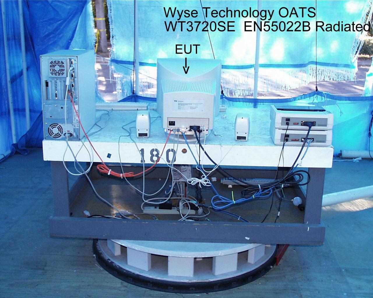
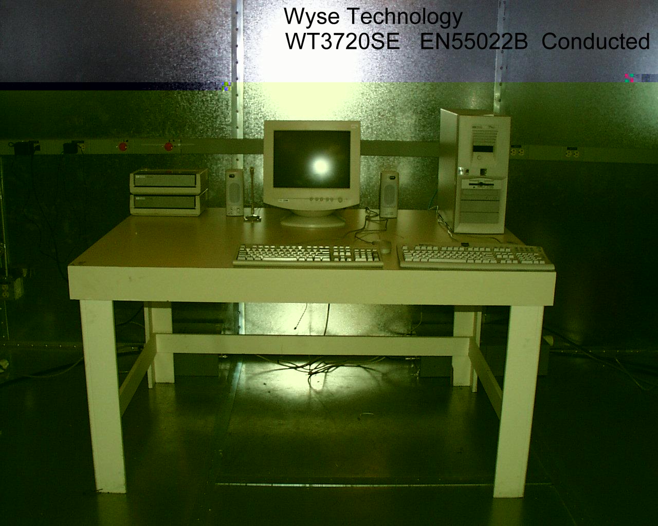
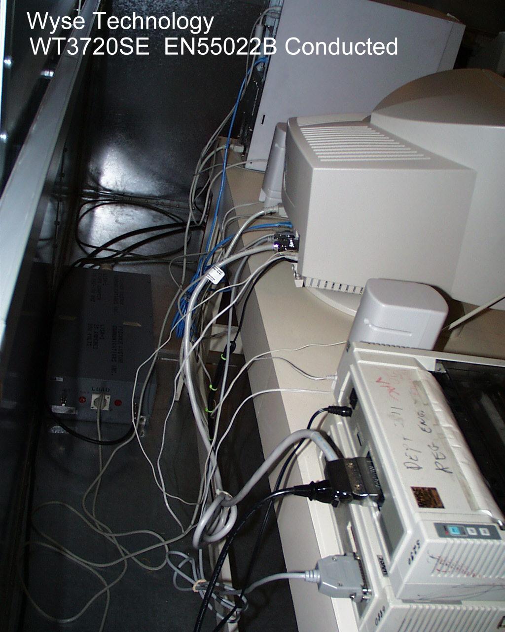
November 4, 1999 To: Ms. Linda Elliott Federal Communication Commission Equipment Approval Services P.O. Box 358315 Pittsburgh, PA 15251-5315 Subject: FCC Part 15 Class B approval of our Windows-based Terminal model WT3720SE Dear Ms. Elliott: We would like to submit our new Windows-based Terminal model WT3720SE to obtain FCC part 15 class B approval under FCC ID DYDWT3720. The Radiated and Line Conductive measurements were performed in accordance with EN55022 Class B. This model is identical to our approved model WT2715SE (DYDWINTERM2700), except for the logic board. The logic board is the same as that used in our approved model WT3320SE (DYDWT3320). With this letter I have provided all the necessary documentation electronically and attached the radiated and conducted setup drawings. All the test equipment information has been included as part of the radiated and conducted test report. Please note that the Anti-Drug letter was submitted to you during the original investigation of our model WT2300 (FCC ID DYDWT2300). Equipment List for the Radiated Measurement test: Support Equipment: HP PC Model: HP Brio PC (a copy of DOC is attached) HP Printer FCC ID: BS46XC2225C Test Equipment: HP Receiver Model 84560A (RES BW: 30KHz-100KHz, VBW: 10KHz-30KHz) Equipment List for the Conducted Measurement test: Support Equipment: HP PC Model: HP Brio PC (a copy of DOC is attached) HP Printer FCC ID: BS46XC2225C Test Equipment: HP Spectrum Analyzer Model 8566B (RES BW: 30 KHz-100KHz, VBW: 10KHz- 30KHz) HP QP Adaptor Model 85650A If you have any questions or need additional information, please contact me at 408.473.2697 (voice), 408.473.2245 (fax), or [email protected] (email). Sincerely Yours, Masood Abrishamcar MouseFCC ID:DZL211029 TEST SETUP FOR RADIATED MEASUREMENT Parallel Printer FCC ID: DSI6XU2225 EUT HP Brio Serial Printer FCC ID: DSI6XU2225 Mic Speaker Keyboard FCC ID: E8HKB-5 9 23 Speaker LAN Cable HP 2225D HP 2225C WT3720SE MouseFCC ID:DZL211029 Support Device Power TEST SETUP FOR CONDUCTED MEASUREMENT Parallel Printer FCC ID: DSI6XU2225 EUT HP Brio Serial Printer FCC ID: DSI6XU2225 Mic Speaker Keyboard FCC ID: E8HKB-5 9 23 Speaker LISN Boxes LAN Cable EUT Power HP 2225D HP 2225C WT3720SE
Test Report
November 4, 1999 WYSE Technology EN 55022-B Test Record for Window Based Terminal Model Number: WT3720SE Tests performed by WYSE Technology 3471 N. First Street, San Jose, CA Test completed: October 21, 1999 Test Engineer: Benton Ng Approved by: Masood Abrishamcar October 21, 1999 1.0INTRODUCTION 1.1 Scope This record is intended to document conformance with the EMC Directive (89/336/EEC) and details the results of testing performed on October 21, 1999 on the WYSE WINTERM model: WT3720SE. 1.2 Purpose Testing was performed to evaluate the emissions performance of the WT3720SE with respect to EN 55022 Class B. 1.3 Summary The Power Adapter WT3720SE was found to be compliant to EN 55022 Class B Emission Requirements. 1.4Testing Requirements Testing was performed using procedures and criteria contained in EN 55022. 2.0 TEST ENVIRONMENT 2.1Test Sample Description WT3720SE is designed to communicate with a host system via Twisted Pair LAN interface on NT Windows Server. Test Software The software used during the test was a continuous loop batch file on Windows NT station. The program creates an entire page of “H”’s and writes the entire page to the screen, and it also prints to the serial and parallel devices as used in the test setup. The cables were moved around to find the maximum emission from the EUT. 2.2 Test Facilities 2.2.1 Emissions Test Site Radiated emissions testing was performed on a weather protected Open Area Test Site. The description of OATS is filed at the WYSE Regulatory Engineering Department. The OATS is located 3471 N. First Street, San Jose, California, USA. Conducted emission testing was performed inside a shielded enclosure (Screen Room) in the WYSE RFI laboratory. The description of screen room is filed at WYSE Regulatory Engineering Department. The Screen Room is located at 3471 N. First Street, San Jose, California, USA. October 21, 1999 2.3 Test Equipment The following are the list of equipment used during the radiation and conducted testing. Radiated: HP Receiver model 84560A (RES BW: 30 KHz-100KHz, VBW: 10KHz – 30KHz) Conducted: HP 85650A Quasi-Peak Adapter HP 8566B Spectrum Analyzer (RES BW: 30KHz –100KHz, VBW: 10KHz – 30KHz) SETUP: In accordance with WYSE Technology test procedure. PROCEDURE: Biconilog antenna was used for frequency range 30MHz - 2 GHz. The frequency range was checked for signals strength. The antenna was then raised and lowered for final maximization. The frequency range was checked with antennas in the horizontal and vertical polarization. 3.0 TEST RESULTS 3.1Test Description CISPR Publication 22:1985, limits and methods of measurements of radio interface of information technology equipment, was the guiding document for the test. The product’s radiated emissions from 30 MHz to 1000 MHz and its power mains conducted emissions from 150 KHz to 30 MHz were measured. 3.2 Test Configuration The EUT was configured with a typical mix of available peripherals which fully configured all types of communications ports of the EUT and exercised it in a typical manner. 3.3Test Procedure For radiated emissions testing, the equipment is installed on a 0.8 meter high non-conductive turntable 10 meter from the receiving antenna mast. The EUT is fully exercised during the test to maximize emissions. The receiving antenna is scanned over the height range of 1 to 4 meters is both polarities and the turntable is rotated with emissions level observed at each frequency. During the process the equipment configuration is also modified by moving the interconnecting cables to find the typical configuration that maximizes emissions at each frequency. The frequency range from 30 MHz to 1000 MHz is explored. Measurement data is compared to Class B limit. October 21, 1999 For conducted emissions testing the equipment is moved to a 0.8 meter high platform and the EUT and Configurations equipment are powered from a different LISNs. Both sides of the AC line are measured and the results compared to the Class B limit. 3.4Test Results A comparison of the measured data with the Class B limit of CISPR shows that Power Adapter WT3720SE was 2.30 dB below the limits at the worst case frequency of 179.99 MHz in a Vertical Polarization. 3.5 Product Specification Model: WT3720SE (Logic Board P/N 991336-01 Rev. A) Clock Circuit: U21 = MK1492-03, P/N 205565-50 Filters: 33 MHZ CLK Line: R85 = 100 Ohm, P/N 370513-13; Z61 = 15pF (not loaded) R86 = 100 Ohm, P/N 370513-13; Z58 = 15pF (not loaded) R87 = 100 Ohm, P/N 370513-13; Z64 = 15pF (not loaded) R88 = 100 Ohm, P/N 370513-13; Z59 = 15pF (not loaded) 14.3 MHZ CLK Line: R89 = 33 Ohm, P/N 370513-13; Z60 = 15pF (not loaded) 48/24 MHZ CLK Line: R90 = 33 Ohm, P/N 370513-13; Z51 = 15pF (not loaded) 24.5 MHZ ( Audio) CLK Line: R91 = 33 Ohm, P/N 370513-13; Z52 = 22pF, P/N 320310-21 U2 = GXLV166, P/N 200062-51 Power Filter U1 = CX5530, P/N 205122-50 Filters: R13 = 68 Ohm, P/N 370513-21; Z6 = 15pF (not loaded) R12 = 68 Ohm, P/N 370513-21; Z5 = 15pF (not loaded) L17, L18 = = 43MTL, P/N 400032-31 RP 1-7 = 100 Ohm, P/N 371338-11 October 21, 1999 Video Circuit: U1 = CX5530, P/N 205122-50 Filters: L1 = 43MTL, P/N 400021-01; C4, C5 = 33pF, P/N 320313-25 L2 = 43MTL, P/N 400021-01; C3, C6 = 33pF, P/N 320313-25 L3 = 43MTL, P/N 400021-01; C2, C7 = 33pF, P/N 320313-25 Termination: R4, R5, R6 = 75 Ohm, P/N 370508-85 Audio Circuit: U15 = LM4546, P/N 205123-53 Filters: C19 = 100 pF, P/N 320313-37 L1-L4 = 43MTL, P/N 400008-03 Audio Connector: J1, J2 = 3.5 MM, P/N 563674-01 Driving Transistor: Q3, Q4 = MMBT3904, P/N 270010-50 Network: U24 = DP83815, P/N 205127-50 Filters: R70, R71 = 49.9 Ohm, P/N 370508-68 U17 = Transformer, Pulse Type '68515,' P/N 429099-51 Filters: C32, C33 = .1 uF, P/N 320338-24 C34 = .01 uF, P/N 320345-13 R72, R73, R74, R75 = 75 Ohm, P/N 370513-22 Zero Ohm Jumpers: RJE = 0 Ohm; Z13, Z14 = (not loaded) RJB = (not loaded) Z22 = P/N 205125-50 Z48 = (not loaded) Z13 = (not loaded) Radiated Emission Test WYSE Technology Inc. 3471 North 1st Street San J…
Text truncated - open the document above for the full version.
Contact Information
Applicant
Benton Ng(Regulatory Engineer)
Technical Contact
Wyse TechnologyMasood Abrishamcar
[email protected]408 473-2697
3471 N. First Street · San Jose, California · United States
Non-Technical Contact
Wyse TechnologySuzanne Thomas
[email protected]408 473-2075
Technical Specifications
| # | Rule Parts | Frequency Range | Power Output |
|---|---|---|---|
| 1 | 15B | - | - |
Other Applications from Wyse Technology
DYDJ400
May 27, 2003Windows-based Terminal
Equipment Class
JBC - Part 15 Class B Computing Device/Personal Computer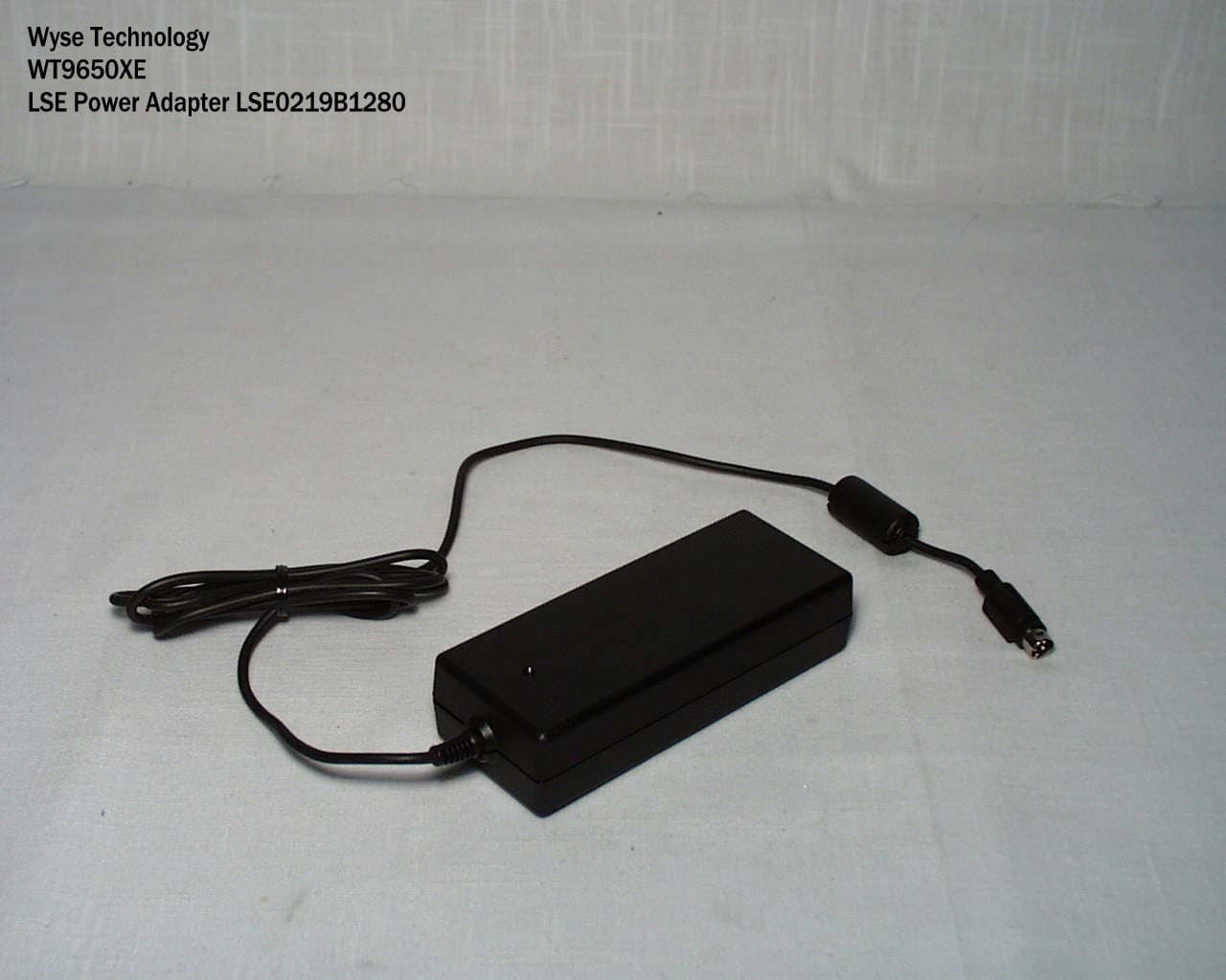
DYDWT9650
Apr 27, 2003Windows-Based Terminal
Equipment Class
JBP - Part 15 Class B Computing Device Peripheral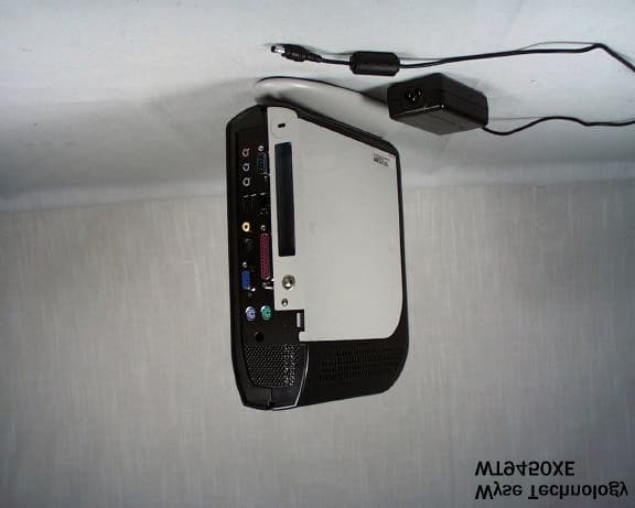
DYDWT9450
Oct 03, 2002Windows-Based Terminal
Equipment Class
JBC - Part 15 Class B Computing Device/Personal Computer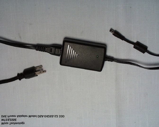
DYDWT3125
Jul 30, 2002Windows-Based Terminal
Equipment Class
JBP - Part 15 Class B Computing Device Peripheral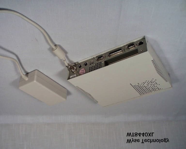
DYDWT8440
Aug 16, 2001Windows-Based Terminal
Equipment Class
JBC - Part 15 Class B Computing Device/Personal Computer