E862WCFEkoTek FOB - 2 way alerting device
Multitone Electronics PLC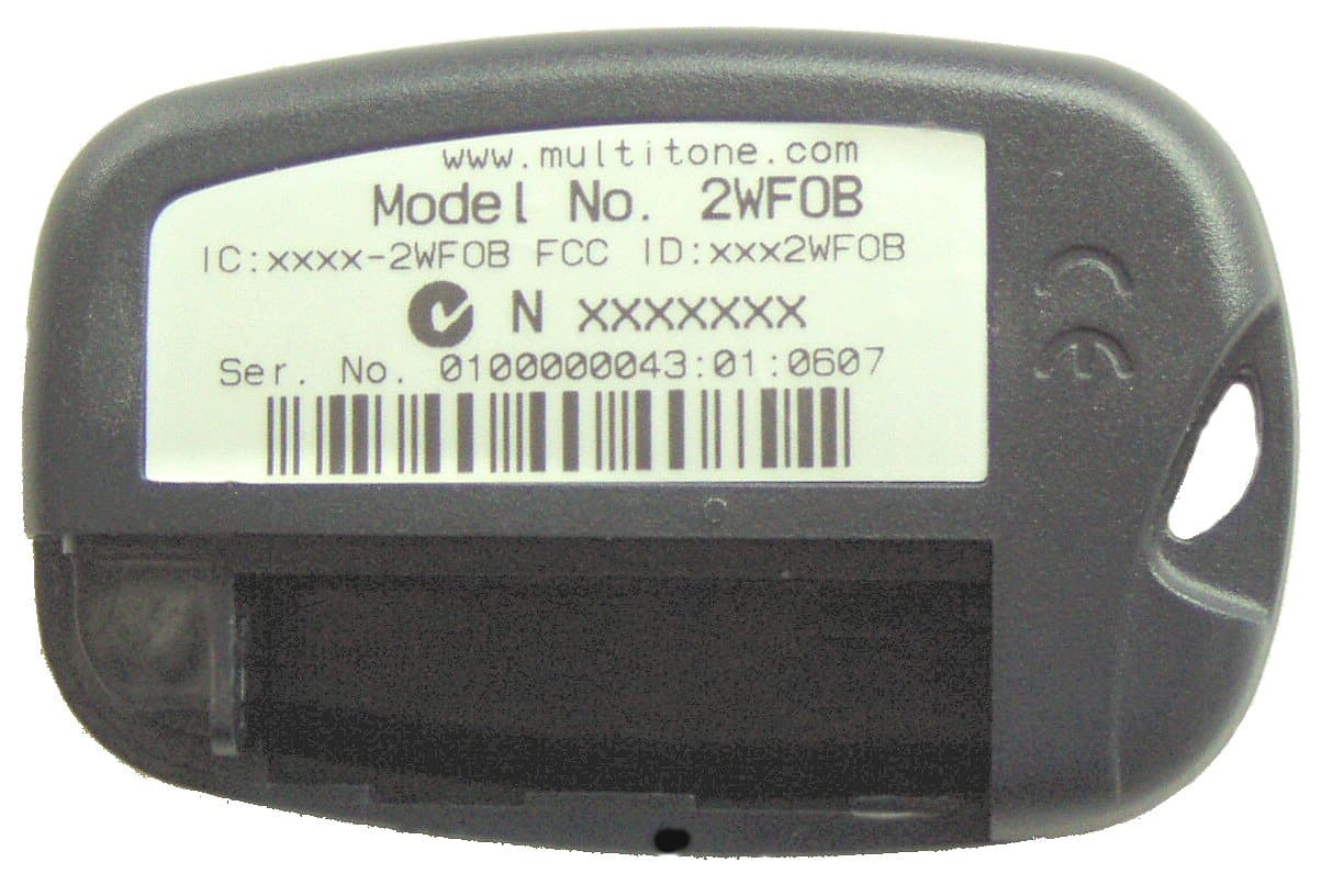
Click to zoom
Application Details
- Equipment Class
- DTS - Digital Transmission System
- Date of Grant
- Nov 04, 2007
- Application Purpose
- Original Equipment
- Date of Application
- Sep 04, 2007
- Equipment Note
- EkoTek FOB - 2 way alerting device
- Frequency Range
- 2405.00000000 - 2480.00000000
- Company
- Multitone Electronics PLC
- Country
- United Kingdom
Documents & Files
Document Text
Text extracted from the exhibit documents filed with the FCC. Open a document above to read the original.
Users Manual
EkoTek Call Fob USER GUIDE For EkoTek Call Fob 9261-8277 (Issue 2.0) EkoTek Call Fob CONTENTS Introduction 3 Compliance 4 General User Information 5 EkoTek System Schematic 6 Switching On Your Call Fob 7 Status and Warning Messages 7 Switching the Call Fob Off 8 Requesting Assistance or Raising an Alarm 8 Cancelling an Alarm 8 Dead Man Alert 9 Man Down Alert 9 Changing the Battery 10 2 EkoTek Call Fob Introduction Your EkoTek Call Fob is a two-way alerting device, incorporating emergency calling and assist functions. Function & Control Buttons Operation of all functions is performed using 2 buttons: The RED button is used for Assist calls. The BLACK button is used to: Switch-on and switch-off the Call Fob Check if the Call Fob is in communication with a network Cancel an alert The RED Alert/Status lamp indicates: If the Call Fob is connected to a network Confirmation of button activation To gain full benefit from this product please read this User Guide carefully. Part No. 9261-8277 Issue 2.0 3 EkoTek Pager Compliance This product complies with the requirements of the EU Radio & Telecommunications Terminal Equipment Directive 99/5/EC. FCC & Industry Canada Statement Of Compliance This device complies with Part 15 of the FCC Rules and Industry Canada Standard RSS 210. Operation is subject to the following two conditions: (1) this device may not cause harmful interference and (2) this device must accept any interference that may cause undesired operation. Unauthorised modification to this equipment will void the user's authority to continue to operate the device within the scope of the Industry Canada and FCC Part 15 Rules. A full technical specification for this product may be obtained from your Multitone representative. WEEE Directive & Product Disposal At the end of its serviceable life, this product should not be treated as household, or general waste. It should be handed over to the applicable collection point for the recycling of electrical and electronic equipment, or returned to the supplier for disposal. Part No. 9261-8277 Issue 2.0 4 EkoTek Call Fob General User Information Radio Reception Your EkoTek Call Fob has been designed to give optimum performance within the coverage area of the transmitting system. As with any radio system there may be areas of poor coverage, where reception may be sporadic, or non-existent. If necessary, consult your system administrator in order to familiarise yourself with these areas. Hazardous Areas The EkoTek Call Fob should not be taken into areas where explosive gas, or dust products, may be present. Call Fob Care Protect your Call Fob from liquids, extreme temperatures and strong magnetic fields. Do not leave your EkoTek Call Fob exposed to strong sunlight. Servicing Should your EkoTek Call Fob require repair, return it to the designated service agent. Do not attempt to open or repair the product, as it contains delicate components and requires specialised test equipment. Part No. 9261-8277 Issue 2.0 5 EkoTek Pager EkoTek System Schematic EkoTek Self Organising & Repairing Wireless Mesh Network Power Adaptor AC Repeater Wireless Call Fob Pager Repeater Repeater Repeater Battery Powered Repeater to Repeater DistanceTypically10to15m Includes Personal Security Alarm Hub With Web Server Part No. 9261-8277 Issue 2.0 6 EkoTek Call Fob Switching On Your Call Fob To activate the Call Fob press and hold the BLACK button for up to 5 seconds. When activated the Call Fob will emit a single audible pip and the alert/status lamp will flash once indicating that it is switched on. After 10 seconds the alert/status lamp will emit a series of single flashes, this indicates that the Call Fob is in the process of detecting the EkoTek wireless network. Once the network is detected and the Call Fob is logged-on, the alert/status lamp will emit a series of double flashes indicating that the Call Fob is now ready to use. Pressing the black button briefly will indicate if the Call Fob is logged-on to a network : the Status lamp will flash twice in succession if it is logged on or once if it is not logged-on. If your EkoTek Call Fob does not switch on, check that a fresh battery is correctly installed and refer to the section entitled: Changing the Call Fob Battery. Note: The Call Fob is automatically activated by the insertion of a battery. Status and Warning Messages Checking Network Status Press and release the BLACK button, the alert/status lamp will indicate EkoTek network connectivity status for a 6-second period. A single flash indicates that the Call Fob is attempting to detect the EkoTek network. A double flash indicates that the EkoTek network has been detected and the Call Fob is fully operational. Changing Battery Notification Part No. 9261-8277 Issue 2.0 7 EkoTek Pager When the battery requires changing the Call Fob will emit a single long beep with an accompanying flash of the alert/status lamp. Please refer to: Changing the Call Fob Battery. Out-of-Range Notification If the Call Fob is out-of-range of the EkoTek wireless network, the Call Fob will emit 2-beeps accompanied by 2-flashes of the alert/status lamp. Switching the Call Fob Off To switch the Call Fob off. Press and hold the BLACK button for 5- seconds this is confirmed by a single flash of alert/status lamp accompanied by a single beep. To confirm that the Call Fob has been de-activated, press and release the BLACK button. If the unit has been de-activated neither the beep nor the alert/status lamp will activate. Requesting Assistance or Raising an Alarm In the event of an Emergency or where immediate assistance is required press the RED button. Depending on how the EkoTek system has been configured this may require a SINGLE or DOUBLE press of the RED button. Please confirm this action with your EkoTek system supervisor. On pressing the RED button the Call Fob will acknowledge the alert with a flash of alert/status lamp accompanied by vibrate and/or a beep depending on configuration. Can…
Text truncated - open the document above for the full version.
Cover Letter(s)
1 Multitone Electronics plc Multitone House, Shortwood Copse Lane, Kempshott, Basingstoke, Hampshire, RG23 7NL Tel: +44 (0)1256 320292 Fax: +44 (0)1256 462643 Website: www.multitone.com Federal Communications Commission, 7435 Oakland Mills Road, Columbia, MD 21046 USA 5th September 2007 Certification Of Product to FCC R & R's, Part 15 Subpart C Multitone EkoTek Series HUB - E862WCF Dear Sirs, We wish to make application for the Certification of the above referenced equipment as part of our EkoTek Series of products, under the auspices of R & R Part 15, Subpart C, Section 15.247. Further separate Form 731's have been completed and supporting exhibits attached, for each individual equipment that further form this Series. The main system data may be found with the application for the 2WHUB device from this Series. The device that is the subject of this application is the: - Call FOB (2WCF) - portable device worn/carried by personnel. Supports deliberate alarm and location call generation and dead-man/man-down activation. Incorporates an LED, buzzer and vibrate motor to provide status and assistance indication. SDR - This equipment may be classed as a Software-Defined Radio. It may be further broadly classified as a Client device in that it requires activation either manually from it's own internal switch devices, or through the reception of a signal from either a HUB, or Repeater unit. It is intended that the control of the software that is used to define the radio parameters for this product, be retained within Multitone. Each unit will be pre-programmed before dispatch and the only radio parameter which may be changed during installation, is the default RF channel within the band. (see System Installation & Configuration Manual with HUB submission). Software Control - The software which controls the RF parameters for all the EkoTek products is Multitone proprietary and is controlled by the company development group and company QA procedure P020/02, which forms part of our ISO 9001certification. As stated above, each equipment is pre-programmed before dispatch and at this time no other external access is to be allowed to the RF parameter software, apart from setting the default RF channel during network installation. The only accessible software control is for network parameter setting. Servicing - It is not intended that the EkoTek FOB products be field serviceable. They will be either returned to Multitone or our agents for repair and/or replaced with another unit. RF Exposure - The nominal RF ERP of the device, is 10mW. This falls below the lower threshold category for General Population exposure (for f 2.4GHz, 25mW) for d <2.5cm. The product is intended to be carried by personnel, either belt-mounted, or in a suitable pocket. Multitone Electronics plc is part of Kantone Holdings Ltd., a member of the Champion Technology group of companies. Registered in England Number 256314 Registered Address, Multitone House, Shortwood Copse Lane, Basingstoke, Hampshire, RG23 7NL 2 Confidentiality - We wish to request Permanent Confidentiality for parts of this item under the terms of R & R 0.457 and as denoted on the Form 731, please see separate request letter. Documentation - Attached is product specific documentation, to be read in conjunction with the generic data sheets and overall system documents attached to the HUB application. I hope that the information supplied enables you to make an initial assessment of the equipment. Once you have formed further questions re this submission, please do not hesitate to contact me. E-mail is probably the most efficient route. Yours sincerely, B.R.Merchant Principal Approvals Engineer Multitone Electronics plc Multitone Electronics plc is part of Kantone Holdings Ltd., a member of the Champion Technology group of companies. Registered in England Number 256314 Registered Address, Multitone House, Shortwood Copse Lane, Basingstoke, Hampshire, RG23 7NL 3 Multitone Electronics plc Multitone House, Shortwood Copse Lane, Kempshott, Basingstoke, Hampshire, RG23 7NL Tel: +44 (0)1256 320292 Fax: +44 (0)1256 462643 Website: www.multitone.com Federal Communications Commission, 7435 Oakland Mills Road, Columbia, MD 21046 USA 5th September 2007 Request For Confidentiality Multitone EkoTek Series FOB - E862WCF Dear Sirs, In accordance with Rule Parts 0.457 & 0.459, we hereby request that the following exhibits entered as part of the certification process for the above product, be held as Permanently Confidential. Schematics:- 2961-8001-2; 0261-8002-2; 3061-8003-2. Block Schematic The reason for this request is that these items are commercially sensitive and have not, or will not be made publicly available. Yours sincerely, B.R.Merchant Principal Approvals Engineer Multitone Electronics plc Multitone Electronics plc is part of Kantone Holdings Ltd., a member of the Champion Technology group of companies. Registered in England Number 256314 Registered Address, Multitone House, Shortwood Copse Lane, Basingstoke, Hampshire, RG23 7NL
External Photos
EkoTek FOB - External Front View EkoTek FOB - Rear View
Internal Photos
EkoTek FOB - General Internal View EkoTek FOB - PCB Topside EkoTek FOB - PCB Underside
Operational Description
EkoTek System Installation and Configuration Manual Survey Installation Configuration Maintenance Part No. 9261-8173 Issue 2 EkoTek System Installation and Configuration Manual Table of Contents Approvals...................................................................................................................................1 Compliance............................................................................................................................1 FCC & Industry Canada Statement of Compliance...............................................................1 WEEE Directive & Product Disposal......................................................................................1 System Overview.......................................................................................................................2 EkoTek Principles..................................................................................................................3 Location Reporting.................................................................................................................4 Beacons..............................................................................................................................5 Two-Way Acknowledgement..............................................................................................5 Two-Way Radio..................................................................................................................5 Frequency Hopping............................................................................................................5 Components...........................................................................................................................6 Single Hub..........................................................................................................................6 Repeater.............................................................................................................................6 2-Way Pager.......................................................................................................................7 Call Fob..............................................................................................................................8 Configuration..........................................................................................................................8 Network Parameters...........................................................................................................8 Diagnostics and Statistics......................................................................................................8 Network Design and Survey......................................................................................................9 The survey unit.....................................................................................................................11 The survey unit.....................................................................................................................11 How to Survey......................................................................................................................12 Installation...............................................................................................................................14 Pre-requisites.......................................................................................................................14 Installing the Hub.................................................................................................................15 Repeaters.............................................................................................................................16 PPP Modem.........................................................................................................................17 Using Windows Hyper Terminal to Set Interface Speed..................................................18 The Browser Interface..........................................................................................................23 Accessing the HUB with the browser interface....................................................................23 Connect the Hub to the PC using Windows XP...................................................................23 Using the Web Browser to Access the EkoTek Hub............................................................25 Main menus..........................................................................................................................26 Day/Night..........................................................................................................................26 Event Log.........................................................................................................................26 Page Device.....................................................................................................................27 Part No. 9261-8173 Issue 2 Page i © 2007 Multitone Electronics PLC Table of Contents Pager Log.........................................................................................................................27 Location............................................................................................................................27 Maintenance Menus.............................................................................................................29 Device Status...................................................................................................................29 Device Status Hub............................................................................................................29 Device Status Repeaters..................................................................................................30 Configuration menus............................................................................................................32 Passw…
Text truncated - open the document above for the full version.
Operational Description
EkoTek Low Power Radio Mesh Networking Table of Contents 1Scope3 2Background3 3Requirements4 4Radio Technology4 5Meeting the Requirements4 5.1 Battery power : IEEE 802.15.44 - 5 5.2 Resilience5 5.3 Self-Configuration6 5.4 Ease of Expansion6 - 7 6Summary7 2 1/Scope This document gives an overview of a radio mesh network and the low power technology that can be used for implementation of the network. 2/Background A mesh network is a type of network where co-operating nodes form connections that are used for traffic flow through the network. The term “mesh” is used as traffic may have more than one potential route through the network, providing the possibility of traffic load sharing and resilience. The Internet is a well known mesh network, where Internet Routers form the network nodes that handle the traffic flow. This document is specifically concerned with low power radio mesh networking and describes an implementation used by Multitone Electronics in its EkoTek range of products. 3 Rep Rep Rep Pager Call Point Call Point Pager Call Point Pager Hub Rep 3/Requirements Key requirements for a low power radio mesh network are : Battery powered with long battery life : as multiple nodes form the mesh network, installation costs would be high if each node required a mains power supply. Battery powering allows nodes to be installed quickly and easily with a very low installation cost. Resilience : failure of any node should not cause the network to fail. The network should automatically route around a failed node. Self-configuration : the number of potential radio paths available in a radio mesh network can be considerable. This makes the network robust but means that manual configuration is not practical. The network must automatically configure routes through the network. Ease of expansion : changes to the network must be straightforward to implement 4/Radio Technology A number of radio technologies exist that could be used to create mesh network- ing products. For Multitone’s EkoTek range of products, the requirement for bat- tery powering with a battery life of at least 2 years meant that the latest technol- ogy low power radio devices were the appropriate solution. The chosen radio technology is IEEE 802.15.4 which specifies a radio technique specifically aimed at battery operated devices and giving a long battery life. 5/Meeting the Requirements 5.1/Battery power : IEEE 802.15.4 This specification defines a radio system that may be used in various ways. In order to minimise power consumption, the ON time of the radio transmitter and receiver must be minimised. This is achieved by operating the node radio in beacon mode. 4 Rep-TXRep-RX 20msec 1000msec Repeater window In beacon mode each node (Repeater) has a specific time window in which it transmits/receives. Outside of this window the node is inactive and therefore battery consumption is minimised. In the above example the node window lasts for 20 msec and repeats every 1000msec. As the window is of relatively short duration, the tx/rx data rate must be relatively high to ensure that sufficient data can flow during the window period :in the case of IEEE 802.15.4 it is 250 kbit/s. 5.2/Resilience Traffic links to neighbouring nodes are continuously tested. Should a link fail, that link is dropped and the node automatically looks for a new link to another node. 5 Node Node Node Node Node Node Node Node Node Node Node Node Node Node Node Node Node Node Node Node Node Node Node Node Node Node Node FAIL Re-route Re-route 5.3/Self-Configuration When a node resets or on failure of a link to an adjacent node, the node performs a radio scan and selects an adjacent node with good signal strength as a route to pass traffic via the network. In the above example, the node that has reset has performed a scan and detected three neighbouring nodes that could potentially be used for traffic links. One of these will be selected, normally based on link testing and signal strength. 5.4/Ease of Expansion Changes to the network, normally expansion but may also involve moving part of the network, must be straightforward to implement. Traditional 1-hop radio networks suffer from the single hop radio path normally requiring multiple wired base stations to provide site coverage, making expansion costly and difficult. A mesh network is easily expanded simply by adding additional nodes (Repeaters) in the required location. In addition, as EkoTek’s Repeaters are battery powered, no wires are required to be installed for expansion, making the task very quick and easy. 6 Node Node Node Node Node Node Potential links Node reset 6/Summary The IEEE 802.15.4 radio network chosen for Multitone’s EkoTek range of products provides the following : Ease and low cost of installation due to the use of battery powered nodes (Repeaters). Long battery life using beacon window tx/rx. Ease of installation as the network self-configures at startup. Resilience as the network automatically re-configures on node or link failure. Easy expansion simply by adding battery powered nodes (Repeaters) where required. 7 EkoTek Personal Security & Lone Worker System Overview Table of Contents 1Scope of Document3 2EkoTek Personal Security / Lone Worker System3 - 4 3Applications4 3.1 Building Security4 3.2 Hospital Security4 3.3 Nurse Call4 3.4 Security Guard Protection4 - 5 3.5 Car Park and Campus Security5 3.6 Co-worker Calling5 3.7 2-Way Task Management5 4EkoTek Principles5 4.1 Self-Organising Mesh Radio6-7 4.2 Accurate Location Reporting8 4.2.1 2-Way Acknowledgement8 4.3 2-Way Radio8 - 9 4.3.1 Frequency Hopping9 5Components9 5.1 Single Hub9 - 10 5.2 Call Fob10 5.3 Repeater10 - 11 5.4 Call Point / Repeater11 5.5 2-Way Pager12 5.5.1 Display of and Response to Assistance Calls12 5.5.2 Display of Webserver Paging Messages12 5.5.3 Paging from External System13 5.5.4 Personal Security Calls13 5.5.5 Powering13 5.6 Configuration13 5.6.1 Network Parameters13 - 14 6Diagnostics and Statistics14 7Specificat…
Text truncated - open the document above for the full version.
RF Exposure Info
Multitone Electronics plc Multitone House, Shortwood Copse Lane, Kempshott, Basingstoke, Hampshire, RG23 7NL Tel: +44 (0)1256 320292 Fax: +44 (0)1256 462643 Website: www.multitone.com Federal Communications Commission, 7435 Oakland Mills Road, Columbia, MD 21046 USA Specific Absorption Rate (SAR) Compliance Statement For Multitone EkoTek Series Call-Fob - FCC ID: E862WCF The Multitone EkoTek 2WCF 2-way Radio Paging & Data equipment (2.405 - 2.48GHz) , contains a low power (10mW) RF transmitter and is intended for portable use with the integral unity gain (or less) antenna supplied. The equipment's performance may be characterized in accordance with the exposure requirements of 47 CFR 1.1307, as below. At the mid-band frequency of the equipment's spectrum of operation, the RF output power level of the equipment falls below the FCC's General Population Low Threshold Exposure Limits, as specified in document OET 65. Derivative analysis of this result is as follows: - For the general uncontrolled population, the Low Threshold power value at distances less than 2.5cm from the body, is given by the formula 60/f GHz mW. For equipment operating @ a mid-band frequency of 2.45GHz, this value computes to 24mW. Therefore, the 2WCF RF O/P level falls below the recommended threshold. Dated this 29th Day Of October 2007 Signed: B.R.Merchant, Principal Approvals Engineer, Multitone Electronics plc Telephone: - +44 1256 320292 e-mail: - [email protected] Multitone Electronics plc is part of Kantone Holdings Ltd., a member of the Champion Technology group of companies. Registered in England Number 256314 Registered Address, Multitone House, Shortwood Copse Lane, Basingstoke, Hampshire, RG23 7NL
Test Report
TEST REPORT FROM RFI GLOBAL SERVICES LTD Test of: Multitone Electronics Plc EkoTek - Fob To: FCC Part 15.247: 2006 (Subpart C) Test Report Serial No: RFI/RPTE2/RP48909JD015A Supersedes Test Report Serial No: RFI/RPTE1/RP48909JD015A This Test Report Is Issued Under The Authority Of Michael Derby, Radio Performance Service Leader: Tested By: Nirav Modi Checked By: Michael Derby Report Copy No: PDF01 Issue Date: 12 July 2007 Test Dates: 04 June 2007 to 19 June 2007 This report is issued in Adobe Acrobat portable document format (PDF). It is only a valid copy of the report if it is being viewed in PDF format with the following security options not allowed: Changing the document, Selecting text and graphics, Adding or changing notes and form fields. This report may be copied in full. The results in this report apply only to the sample(s) tested. RFI GLOBAL SERVICES LTD TEST REPORT S.No. RFI/RPTE2/RP48909JD015A Page: 2 of 40 Issue Date: 12 July 2007 Test of: Multitone Electronics Plc EkoTek - Fob To: FCC Part 15.247: 2006 (Subpart C) This page has been left intentionally blank. RFI GLOBAL SERVICES LTD TEST REPORT S.No. RFI/RPTE2/RP48909JD015A Page: 3 of 40 Issue Date: 12 July 2007 Test of: Multitone Electronics Plc EkoTek - Fob To: FCC Part 15.247: 2006 (Subpart C) Table of Contents 1. Client Information ............................................................................................................. 4 2. Equipment Under Test (EUT) ........................................................................................... 5 3. Test Results ...................................................................................................................... 7 4. Deviations from the Test Specification .......................................................................... 7 5. Operation of the EUT during Testing .............................................................................. 8 6. Summary of Test Results................................................................................................. 9 7. Measurements, Examinations and Derived Results.................................................... 10 8. Measurement Uncertainty.............................................................................................. 30 9. Measurement Methods................................................................................................... 31 Appendix 1. Test Equipment Used.................................................................................... 36 Appendix 2. Test Configuration Drawings ....................................................................... 38 RFI GLOBAL SERVICES LTD TEST REPORT S.No. RFI/RPTE2/RP48909JD015A Page: 4 of 40 Issue Date: 12 July 2007 Test of: Multitone Electronics Plc EkoTek - Fob To: FCC Part 15.247: 2006 (Subpart C) 1. Client Information Company Name: Multitone Electronics Plc Address: Multitone House Shortwood Copse Lane Kempshott Basingstoke Hampshire RG23 7NL UK Contact Name: Mr B Merchant RFI GLOBAL SERVICES LTD TEST REPORT S.No. RFI/RPTE2/RP48909JD015A Page: 5 of 40 Issue Date: 12 July 2007 Test of: Multitone Electronics Plc EkoTek - Fob To: FCC Part 15.247: 2006 (Subpart C) 2. Equipment Under Test (EUT) The following information (with the exception of the Date of Receipt) has been supplied by the client: 2.1. Identification of Equipment Under Test (EUT) Description: Call Fob Brand Name: Multitone Model Name or Number: EkoTek – Call Fob Unique Type Identification: 2WCF Serial Number: 35 Hardware Version: D Software Version: Issue 1 – modified for test coverage FCC ID Number: E862WCF Country of Manufacture: Malacca Date of Receipt: 04 June 2007 2.2. Accessories No accessories were supplied with the EUT. 2.3. Description of EUT The equipment under test is a Personal Alarm Device. 2.4. Modifications Incorporated in EUT During the course of testing the EUT was not modified. RFI GLOBAL SERVICES LTD TEST REPORT S.No. RFI/RPTE2/RP48909JD015A Page: 6 of 40 Issue Date: 12 July 2007 Test of: Multitone Electronics Plc EkoTek - Fob To: FCC Part 15.247: 2006 (Subpart C) 2.5. Additional Information Related to Testing Power Supply Requirement: Internal battery supply of 1.5 V Intended Operating Environment: Residential Commercial Light Industry Equipment Category: 802.15.4 Type of Unit: Portable Transceiver Transmit Frequency Range: 2.405 GHz to 2.480 GHz Channel ID Channel Number Channel Frequency (GHz) Bottom 1 2.405 Middle 9 2.445 Transmit Channels Tested: Top 16 2.480 Maximum Peak Power Output (EIRP) 11.5 dBm RFI GLOBAL SERVICES LTD TEST REPORT S.No. RFI/RPTE2/RP48909JD015A Page: 7 of 40 Issue Date: 12 July 2007 Test of: Multitone Electronics Plc EkoTek - Fob To: FCC Part 15.247: 2006 (Subpart C) 3. Test Results Reference: FCC Part 15.247: 2005 Subpart C Title: Code of Federal Regulations, Part 15.247 (47CFR22) (Intentional Radiators operating within the bands 902-928 MHz, 2400-2483.5 MHz and 5725-5850 MHz) 3.1. Methods and Procedures The methods and procedures used were as detailed in: ANSI/TIA-603-B-2003 Land Mobile Communications Equipment, …
Text truncated - open the document above for the full version.
Contact Information
Applicant
B. R. Merchant(Principal Approvals Engineer)
Technical Contact
Multitone Electronics plcBrian Ronald Merchant
[email protected]+441256845148
Multitone House · Basingstoke · United Kingdom
Non-Technical Contact
Multitone Electronics plcBrian Ronald Merchant
[email protected]+441256845148
Test Firm
UL VS LtdDarren Rust
Technical Specifications
| # | Rule Parts | Frequency Range | Power Output |
|---|---|---|---|
| 1 | 15C | 2.40 GHz - 2.48 GHz | 10.00 mW |
Other Applications from Multitone Electronics PLC
E86EKOCPLVRM
Feb 26, 2026EKOTek call point
Equipment Class
DTS - Digital Transmission System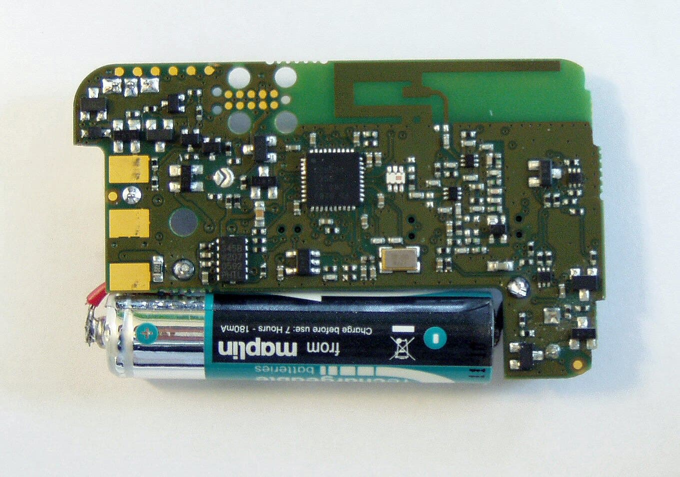
E86EKOFOB
Apr 10, 20132 way alarm and alerting device
Equipment Class
DTS - Digital Transmission System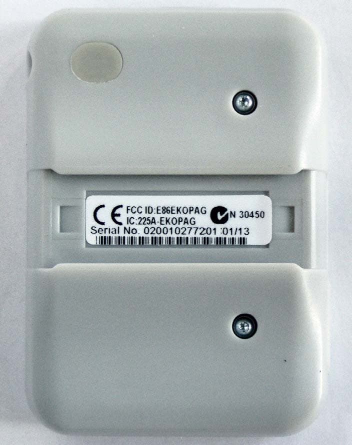
E86EKOPAG
Apr 02, 2013Alpha-numeric 2 way alarm and paging device
Equipment Class
DTS - Digital Transmission System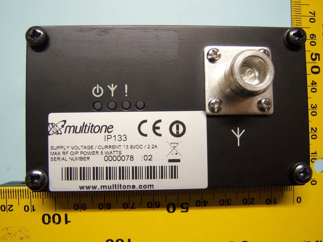
E86IP133
Feb 07, 2012Multitone I-Page � IP133
Equipment Class
TNB - Licensed Non-Broadcast Station TransmitterE86RPT503
Aug 07, 2008UHF Paging Transmitter
Equipment Class
TNB - Licensed Non-Broadcast Station Transmitter