E86EKOFOB2 way alarm and alerting device
Multitone Electronics PLC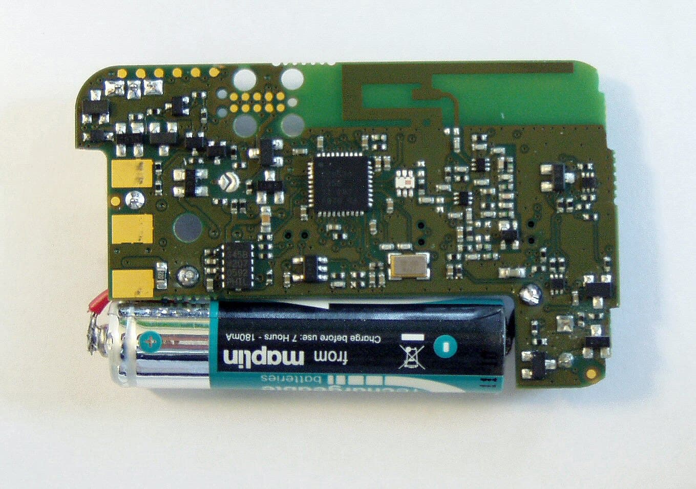
Click to zoom
Application Details
- Equipment Class
- DTS - Digital Transmission System
- Date of Grant
- Apr 10, 2013
- Application Purpose
- Original Equipment
- Date of Application
- Feb 06, 2013
- Equipment Note
- 2 way alarm and alerting device
- Frequency Range
- 2405.00000000 - 2480.00000000
- Company
- Multitone Electronics PLC
- Country
- United Kingdom
Documents & Files
Document Text
Text extracted from the exhibit documents filed with the FCC. Open a document above to read the original.
Users Manual
www.multitone.com Multitone Electronics plc EkoTek Fob Quick Guide 9261-9209 EkoTek-Fob/QUG/Iss. 5 2 of 8 EU Declaration of Conformity In Accordance With Article 6.3 of the EU Radio & Telecommunication Terminal Equipment R & TTE Directive 99/5/EC. As the manufacturer, we declare under our sole responsibility that the EKOFOB equipment conforms to all the applicable essential requirements of the EU Directive 99/5/EC, in accordance with the procedures of Annex II of the Directive and the following technical standards:- ETSI EN 300 328 (Directive article 3.2); ETSI EN 301 489-1; ETSI EN 301 489-3 (Directive article 3.1{b}); EN 60950 (Directive article 3.1{a}). These equipments are designated as Class 1, Sub Class 21 (non-specific short range device) under the terms of the Directive and TCAM (Telecommunication Conformity Assessment and Market Surveillance Committee) classification scheme. A full copy of the Declaration of Conformity may be obtained from www.multitone.com , or upon application to Multitone. FCC & Industry Canada Statement of Compliance This device complies with Part 15 of the FCC Rules and Industry Canada Standards RSS GEN & RSS210. Operation is subject to the following two conditions: (1) this device may not cause harmful interference and (2) this device must accept any interference that may cause undesired operation. Unauthorised modification to this equipment will void the user's authority to continue to operate the device within the scope of the Industry Canada and FCC Part 15 Rules. WEEE Directive & Product Disposal At the end of its serviceable life, this product should not be treated as household or general waste. It should be handed over to the applicable collection point for the recycling of electrical and electronic equipment, or returned to Multitone or their agent, for disposal. 9261-9209 EkoTek-Fob/QUG/Iss. 5 3 of 8 EkoTek Fob LED Grey button – on/off and alarm cancel Blue button – assist alarm Red button – emergency alarm Turning on the device • To turn the fob on for the first time, place the device in the charger and remove after the recommended 12 hours. Please note: The pager make take a few minutes to charge before turning on. • To turn the device on press the grey button for up to 3 seconds, the device will beep to acknowledge the action. Turning off the device • To turn the device off, press and hold the grey button for up to 3 seconds, the device will beep to acknowledge the action. 9261-9209 EkoTek-Fob/QUG/Iss. 5 4 of 8 Beep and Vibrate The beep and vibrate alerts are set by the system administrator on the hub. The Call Fob beep/vibrate is used to indicate a change in the status of an alarm and operates in conjunction with the LED, to acknowledge operations or conditions. Connecting to a Network If the Fob has been taken off-network, press the grey button when in range of a network to make the Fob quickly re-join the network (e.g. when arriving at work in the morning). Charging the Battery • The fob is fitted with a AAA Ni-MH rechargeable battery. • To charge the battery, place the device in the charger, the LED will flash to acknowledge charging; - 1 flash every 3 seconds – charging - 2 flashes every 3 seconds – > charged. Do NOT attempt to remove the battery. Opening the device will invalidate any warranty. Please give the device to your administrator for return to a Multitone Agent for service. 9261-9209 EkoTek-Fob/QUG/Iss. 5 5 of 8 Raising and clearing alarms Emergency Alarm (red button): (if enabled) • Send Emergency Assist call (1 or 2 pushes – configured by supervisor). • When the Emergency Alert button pressed you will see the following: o Alarm being sent: Slow flash o Alarm delivered: 2 Fast flashes o Alarm accepted: 3 Fast flashes (only when accepted by another user). • To clear a raised alarm press the grey button (short press). Assist Alarm (blue button): (if enabled) • 1 push raises assist alarm (alarm automatically cleared). When pressed you will see the following: o Alarm being sent: Slow flash o Alarm delivered: 2 Fast flashes. Wander alarm (if enabled) • Zones which are restricted are set and configured by the administrator. • Upon entering one of these restricted zones, the fob will activate a response (as configured by the administrator): o Audible and vibrate alert o Audible alert o Vibrate alert. • An alarm message will be sent to pagers configured by the administrator. Man-Down Operation (if enabled by Supervisor) • To prevent the automatic man-down alarm being sent, keep the Call Fob in an upright position (normally worn in the Call Fob holster on a belt). • The device will beep prior to sending the man-down alert, to prevent the alarm from being sent, return the device to an upright position. • To clear alarm press the grey button (short press). 9261-9209 EkoTek-Fob/QUG/Iss. 5 6 of 8 Dead-Man Operation (if enabled by Supervisor) • Press the grey button to respond to periodic dead-man check (audible beep) and prevent automatic alarm generation. • To clear alarm press the grey button (short press). 9261-9209 EkoTek-Fob/QUG/Iss. 5 7 of 8 Status Indicators Checking if the fob is on the network: • To check if the device is on the network, press grey button (short press). (LED : one flash = off network, two flashes = on network). Low battery status alarm • This alarm occurs when the battery reaches less than 25% charge. • The notification is an audible and vibrate alert. • The unit will continue to operate, but should be placed on charge at the earliest opportunity. Out of network range alarm • This alarm occurs when the fob is out of range of the EkoTek mesh network. • The notification is configured by the administrator to: • Audible and vibrate alert • Audible alert • Vibrate alert FM 20122 Multitone Electronics plc, Multitone House, Shortwood Copse Lane, Kempshott, Basingstoke, Hampshire, RG23 7NL Telephone: +44 (0)1256 320292 Fax: +44 (0)1256462643 Email: [email protected] Web: www.multitone.com This document is for guidance only.…
Text truncated - open the document above for the full version.
Users Manual
Buttons (from top to bottom): Grey button: on/off and alarm cancel Blue button: assist alarm Red button: emergency alarm 1. Turning on the device To turn the fob on for the first time, place the device in the charger and remove after the recommended 12 hours. The pager may take a few minutes to charge before turning on. Otherwise, to turn the device on press the grey button for up to 3 seconds, the device will beep to acknowledge the action Turning off the device To turn the device off, press and hold the grey button for up to 3 seconds, the device will beep to acknowledge the action Charging the battery lThe fob is fitted with a AAA Ni-Mh rechargeable battery lTo charge the battery, place the device in the charger, the LED will flash to acknowledge charging: 1 flash every 3 seconds – charging 2 flashes every 3 seconds – charged Do NOT attempt to remove the battery. Opening the device will invalidate any warranty. Please give the device to your administrator for return to a Multitone Agent for service. 2. 3. Emergency Alarm (red button): (if enabled) lSend Emergency Assist call (1 or 2 pushes as configured by supervisor) lWhen the Emergency Alert button pressed you will see the following: Alarm being sent: Slow flash Alarm delivered: 2 Fast flashes Alarm accepted: 3 Fast flashes (only when accepted by another user) lTo clear a raised alarm press the grey button (short press) 4. Assist Alarm (blue button):(if enabled) l1 push raises assist alarm (alarm automatically cleared) lWhen pressed you will see the following: Alarm being sent: Slow flash Alarm delivered: 2 Fast flashes Wander Alarm: Upon entering a restricted zone, the fob activates an alert. Man-Down Alarm: If unit is tilted more than 45 degrees for longer than the configured trigger period Dead-Man Alarm: If a response is not entered to the periodic prompt Status Indicators lTo check if the device is on the network press grey button (short press) (LED : one flash = off network, two flashes = on network) lA low battery status alarm will be activated when the battery reaches less than 25% (audible and vibrate) lWhen the fob is out of range of the EkoTek network, an alarm will be activated to notify the user 5. 6. Welcome to your EkoTek Fob Quick Guide Further instructions are available from the multitone support site www.multitone.com For further information or troubleshooting, please refer to your system administrator. E U D e c l a r a t i o n o f C o n f o r m i t y I n A c c o r d a n c e W i t h A r t i c l e 6 . 3 o f t h e E U R a d i o & T e l e c o m m u n i c a t i o n T e r m i n a l E q u i p m e n t R & T T E D i r e c t i v e 9 9 / 5 / E C . A s t h e m a n u f a c t u r e r , w e d e c l a r e u n d e r o u r s o l e r e s p o n s i b i l i t y t h a t t h e E K O F O B e q u i p m e n t c o n f o r m s t o a l l t h e a p p l i c a b l e e s s e n t i a l r e q u i r e m e n t s o f t h e E U D i r e c t i v e 9 9 / 5 / E C , i n a c c o r d a n c e w i t h t h e p r o c e d u r e s o f A n n e x I I o f t h e D i r e c t i v e a n d t h e f o l l o w i n g t e c h n i c a l s t a n d a r d s : - E T S I E N 3 0 0 3 2 8 ( D i r e c t i v e a r t i c l e 3 . 2 ) ; E T S I E N 3 0 1 4 8 9 - 1 ; E T S I E N 3 0 1 4 8 9 - 3 ( D i r e c t i v e a r t i c l e 3 . 1 { b } ) ; E N 6 0 9 5 0 ( D i r e c t i v e a r t i c l e 3 . 1 { a } ) . T h e s e e q u i p m e n t s a r e d e s i g n a t e d a s C l a s s 1 , S u b C l a s s 2 1 ( n o n - s p e c i f i c s h o r t r a n g e d e v i c e ) u n d e r t h e t e r m s o f t h e D i r e c t i v e a n d T C A M ( T e l e c o m m u n i c a t i o n C o n f o r m i t y A s s e s s m e n t a n d M a r k e t S u r v e i l l a n c e C o m m i t t e e ) c l a s s i f i c a t i o n s c h e m e . A f u l l c o p y o f t h e D e c l a r a t i o n o f C o n f o r m i t y m a y b e o b t a i n e d f r o m w w w . m u l t i t o n e . c o m , o r u p o n a p p l i c a t i o n t o M u l t i t o n e . F C C & I n d u s t r y C a n a d a S t a t e m e n t o f C o m p l i a n c e T h i s d e v i c e c o m p l i e s w i t h P a r t 1 5 o f t h e F C C R u l e s a n d I n d u s t r y C a n a d a S t a n d a r d s R S S G E N & R S S 2 1 0 . O p e r a t i o n i s s u b j e c t t o t h e f o l l o w i n g t w o c o n d i t i o n s : ( 1 ) t h i s d e v i c e m a y n o t c a u s e h a r m f u l i n t e r f e r e n c e a n d ( 2 ) t h i s d e v i c e m u s t a c c e p t a n y i n t e r f e r e n c e t h a t m a y c a u s e u n d e s i r e d o p e r a t i o n . U n a u t h o r i s e d m o d i f i c a t i o n t o t h i s e q u i p m e n t w i l l v o i d t h e u s e r ' s a u t h o r i t y t o c o n t i n u e t o o p e r a t e t h e d e v i c e w i t h i n t h e s c o p e o f t h e I n d u s t r y C a n a d a a n d F C C P a r t 1 5 R u l e s . W E E E D i r e c t i v e & P r o d u c t D i s p o s a l A t t h e e n d o f i t s s e r v i c e a b l e l i f e , t h i s p r o d u c t s h o u l d n o t b e t r e a t e d a s h o u s e h o l d o r g e n e r a l w a s t e . I t s h o u l d b e h a n d e d o v e r t o t h e a p p l i c a b l e c o l l e c t i o n p o i n t f o r t h e r e c y c l i n g o f e l e c t r i c a l a n d e l e c t r o n i c e q u i p m e n t , o r r e t u r n e d t o M u l t i t o n e o r t h e i r a g e n t , f o r d i s p o s a l . L i t e r a t u r e N o : E k o T e k F o b / c c / i s s u e 1 P r o d u c t N o . : F O B - 9 2 6 1 - 9 1 6 7
Users Manual
www.multitone.com EkoTek System Installation and Configuration Manual Survey Installation Configuration Maintenance EkoTek System Installation and Configuration Manual 9261-8173 issue: 8 Page i © 2012 Multitone Electronics Plc Table of contents Table of contents...........................................................................................................i Approvals .....................................................................................................................3 Compliance...............................................................................................................3 FCC and Industry Canada Statement of Compliance ..............................................3 WEEE Directive and Product Disposal.....................................................................3 System Overview .........................................................................................................4 1. EkoTek principles .................................................................................................5 2. Location reporting.................................................................................................6 3. Alarms ..................................................................................................................7 4. Location alarm ......................................................................................................7 5. Beacons................................................................................................................7 6. Two-way acknowledgement .................................................................................7 7. Two-way radio ......................................................................................................7 8. Frequency hopping...............................................................................................8 9. ESPA and TAP paging I/O ...................................................................................8 10. Configuration ......................................................................................................8 11. Network parameters ...........................................................................................9 12. Diagnostics and statistics ...................................................................................9 Components...............................................................................................................10 1. Hub .....................................................................................................................10 2. Repeater and mains-powered repeater..............................................................10 3. Solar repeater.....................................................................................................11 4. Call point and mains-powered call point.............................................................11 5. Call fob ...............................................................................................................12 6. Pager ..................................................................................................................13 7. Quad pager charging rack ..................................................................................14 Synchronised Ethernet Repeater ...............................................................................15 1. Overview.............................................................................................................15 Network design and survey........................................................................................17 1. Overview.............................................................................................................17 2. Prerequisites.......................................................................................................17 3. Placement rules..................................................................................................17 4. The survey unit ...................................................................................................18 5. How to survey.....................................................................................................21 Installation ..................................................................................................................22 1. Preparation .........................................................................................................22 2. Installing the hub and IP slave hub.....................................................................23 3. Installing the repeater, mains powered repeater and call point ..........................24 4. Installing the solar repeater ................................................................................28 5. Installing Synchronised Ethernet Repeater (SER) .............................................30 6. Installing the PPP modem ..................................................................................31 7. Installing the four-way pager charging rack ........................................................37 8. Browser interface setup......................................................................................38 9. Main menus ........................................................................................................41 10. Maintenance menus .........................................................................................43 11. Configuration menus ........................................................................................47 12. SER overview ...................................................................................................49 13. Final checks......................................................................................................70 14. Configuring SERs .............................................................................................71 Synchroni…
Text truncated - open the document above for the full version.
Users Manual
EkoTek Literature No: ekotek/ds/issue 2 Multitone Electronics plc, Multitone House, Shortwood Copse Lane, Basingstoke, Hampshire, RG23 7NL Tel: +44 (0)1506 418198Fax: +44 (0)1506 411711Email: [email protected]: www.multitone.com This brochure is for guidance only. Products and services offered are subject to availability and may differ from those described or illustrated in this brochure as a result of changes. Specifications are subject to change without notice. Multitone Electronics plc is part of Kantone Holdings Ltd, a member of the Champion Technology group of companies. Registered office: Multitone Electronics plc, Shortwood Copse Lane, Kempshott, Basingstoke, Hampshire, RG23 7NL. Registered in England No. 256314. FM 20122 EkoTek is a battery operated mesh network based on the 802.15.4 standard which can be easily implemented within a building without routing wires. EkoTek provides two-way communication to user devices, allowing them to raise an alarm and receive messages from team members to know help is on the way. Call Fob The call fob allows an assistance call to be generated either by the user pressing a button, or automatically by the dead-man or man-down features. Accurate location information is regularly obtained from the repeater network and relayed to teams for immediate assistance. EkoTek Pager The pager is a multi-functional device, displaying received messages with acknowledgement, plus the ability to generate an alarm from the button, snatch cord (panic), dead-man or man-down features. Its display shows alarms from other pagers and call fobs, allowing the user to accept the alarm and signal back to confirm that assistance is on its way. Two Levels of Alarm For both the EkoTek pager and fob there are two levels of alarm. Emergency Alarm: lRed button: Single or double press raises an alarm with escalation lMan-down: On suffering a fall, an alarm is raised with escalation lDead-man: Raises alarm if no response is received to a scheduled request (with escalation) lSnatch Alarm (pager only): Raises alarm if pager is snatched from cord Assist Alarm: lLow priority alarm to call for assistance (no escalation) 1 Hub The hub is the system’s central control unit, displaying assistance call messages, the calling user and location. Device configuration can be changed using a PC running web browser software such as Internet Explorer. Network and device data can be collected. Pager messages, production of groups of pagers and location display allow call fob or pagers users to be located. EkoTek systems can be extended using Synchronized Ethernet Repeaters (SERs). Up to 8 SERs can be used to extend a system. Repeater Battery operated with a battery life of up to 2 years which form the mesh radio network. Technical specification Radio Performance lRadio frequency: 2405-2480MHz lRadio channels: 16 lChannel operating mode: Fixed frequency, or frequency hopping lMaximum no. of radio channels simultaneously used per system: 16 lRadio power: 10mW lRadio coding: modulation format OQPSK DSSS IEEE 802.15.4 Electrical Specification lHub power: AC-DC power adaptor lHub back-up batteries: 3 x C cell NiMH rechargeable batteries lRepeater power: 2 X D cell high capacity alkaline manganese batteries lPager power: 1 X NiMH rechargeable battery (not replaceable) lCall fob power: 1 X NiMH rechargeable battery (not replaceable) lMains powered repeater power: 9.5-15V DC 15mA, with proprietary rechargeable battery pack as back-up lCharging rack: AC-DC power adaptor lCall point power: 2 X D cell high capacity alkaline manganese batteries lSynchronized Ethernet Repeater: power over ethernet with a back-up of 2AA NiMH rechargeable batteries lMains powered call point: 11 – 15V 25mA, with proprietary rechargeable battery pack as back-up lBattery life: EkoTek pager: up to 2 weeks * EkoTek fob: up to 4 weeks* System Maximums lMax no. of pagers: 127 lMax no. of devices per system: 500 (inc. pagers, fobs, repeaters and hub) External Connections (hub) l2 x serial port: 300 – 9600 baud Port A: ESPA input/output TAP input/output Port B: TAP input ESPA input Note: TAP & ESPA protocols are not standardised and require tests for compatibility. *dependent on usage EkoTek Personal Security System
Attestation Statements
Multitone Electronics plc, Multitone House, Shortwood Copse Lane, Kempshott, Basingstoke, Hampshire, RG23 7NL Telephone: +44 (0)1256 320292 Fax: +44 (0)1256462643 Email: [email protected] Web: www.multitone.com Registered in England & Wales No. 256314. Registered VAT No: GB 232150709. FM 20122 Federal Communications Commission, 7435 Oakland Mills Road, Columbia, MD 21046 USA Specific Absorption Rate (SAR) Compliance Statement For Multitone EkoTek Series Pager - FCC ID: E86EKOFOB The Multitone EKOFOB 2-way Radio Paging & Data equipment (2.405 - 2.48GHz), contains a low power (10mW) RF transmitter and is intended for portable use with the integral unity gain (or less) antenna supplied. The equipment's performance may be characterized in accordance with the exposure requirements of 47 CFR 1.1307, as below. At the mid-band frequency of the equipment's spectrum of operation, the RF output power level of the equipment falls below the FCC's General Population Low Threshold Exposure Limits, as specified in document OET 65. Derivative analysis of this result is as follows: - For the general uncontrolled population, the Low Threshold power value at distances less than 2.5cm from the body is given by the formula 60/f GHz mW. For equipment operating @ a mid-band frequency of 2.45GHz, this value computes to 24mW. Therefore, the EKOFOB RF O/P level falls below the recommended threshold. Dated this 7th Day of February 2013 Signed: B.R. Merchant, Principal Approvals Engineer, Multitone Electronics plc Telephone: - +44 1256 320292/ (direct) 845148 e-mail: - [email protected] Multitone Electronics plc Multitone House Shortwood Copse Lane Kempshott, Basingstoke Hampshire, RG23 7NL Tel: +44 (0)1256 320292 Fax: +44 (0)1256 462643 Email: [email protected] Web: www.multitone.com
Cover Letter(s)
Multitone Electronics plc, Multitone House, Shortwood Copse Lane, Kempshott, Basingstoke, Hampshire, RG23 7NL Telephone: +44 (0)1256 320292 Fax: +44 (0)1256462643 Email: [email protected] Web: www.multitone.com Registered in England & Wales No. 256314. Registered VAT No: GB 232150709. FM 20122 Federal Communications Commission, 7435 Oakland Mills Road, Columbia, MD 21046 USA 7th February 2013 Request for Confidentiality Multitone EkoTek Series Pager - E86EKOFOB Dear Sirs, In accordance with Rule Parts 0.457 & 0.459, we hereby request that the following exhibits entered as part of the certification process for the above product, be held as Permanently Confidential. Schematics:- Schematic Dwg. Nos. 2961-8999; 0261-9000; 3061-9001. Functional Block Schematics Parts list The reason for this request is that these items are commercially sensitive and have not, or will not be made publicly available. Yours sincerely, B.R. Merchant, Principal Approvals Engineer, Multitone Electronics plc Telephone: - +44 1256 320292/ (direct) 845148 e-mail: - [email protected] Multitone Electronics plc Multitone House Shortwood Copse Lane Kempshott, Basingstoke Hampshire, RG23 7NL Tel: +44 (0)1256 320292 Fax: +44 (0)1256 462643 Email: [email protected] Web: www.multitone.com
Cover Letter(s)
Multitone Electronics plc, Multitone House, Shortwood Copse Lane, Kempshott, Basingstoke, Hampshire, RG23 7NL Telephone: +44 (0)1256 320292 Fax: +44 (0)1256462643 Email: [email protected] Web: www.multitone.com Registered in England & Wales No. 256314. Registered VAT No: GB 232150709. FM 20122 Federal Communications Commission, 7435 Oakland Mills Road, Columbia, MD 21046 USA 13th March 2013 Response to e-mail 12/08/2013 Ref. EA662618 Multitone EkoTek Pager - E86EKOFOB Dear Sir/Madam, In reply to your e-mail ref. our submission, I offer the following responses:- 1. As with the EKOPAG (EA737779) equipment, this was tested by an external test house and no photographs were included in the test report. We do not have any other photo’s of testing, but if necessary I can approach the test house and see if something can be arranged retrospectively. 2. I did not realise that a separate letter was required to request short term confidentiality; I assumed it was automatic until approval had been granted. Please ignore this request if possible. 3. See 2. 4. I thought that the SAR Compliance Statement had been included in the original uploads. Sorry for the omission; a revised statement has been submitted under a separate cover. I trust that the information supplied is sufficient to cover your requirements, but if you need any further please do not hesitate to contact me. Yours sincerely, B.R. Merchant, Principal Approvals Engineer, Multitone Electronics plc Telephone: - +44 1256 320292/ (direct) 845148 e-mail: - [email protected]
Cover Letter(s)
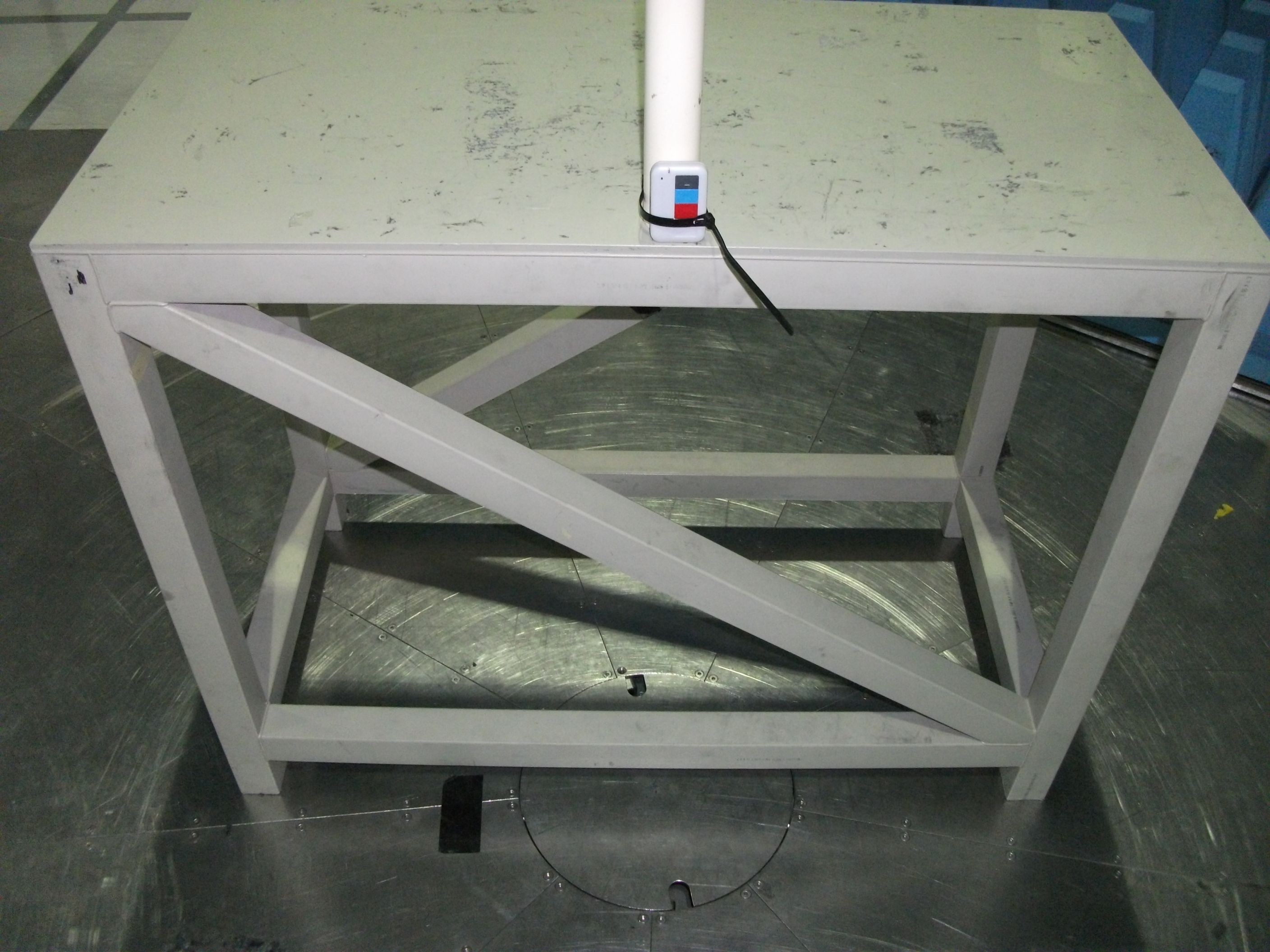
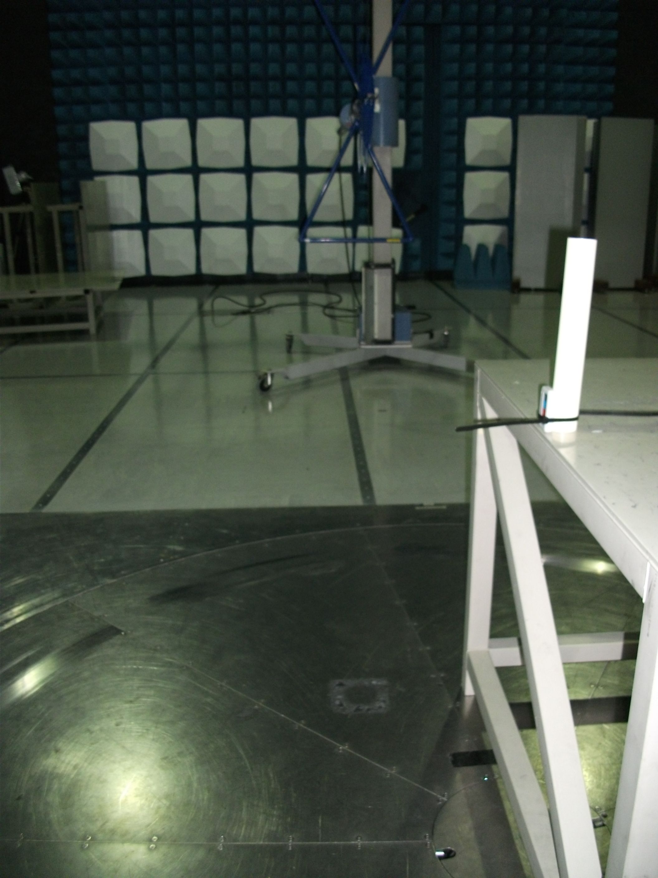
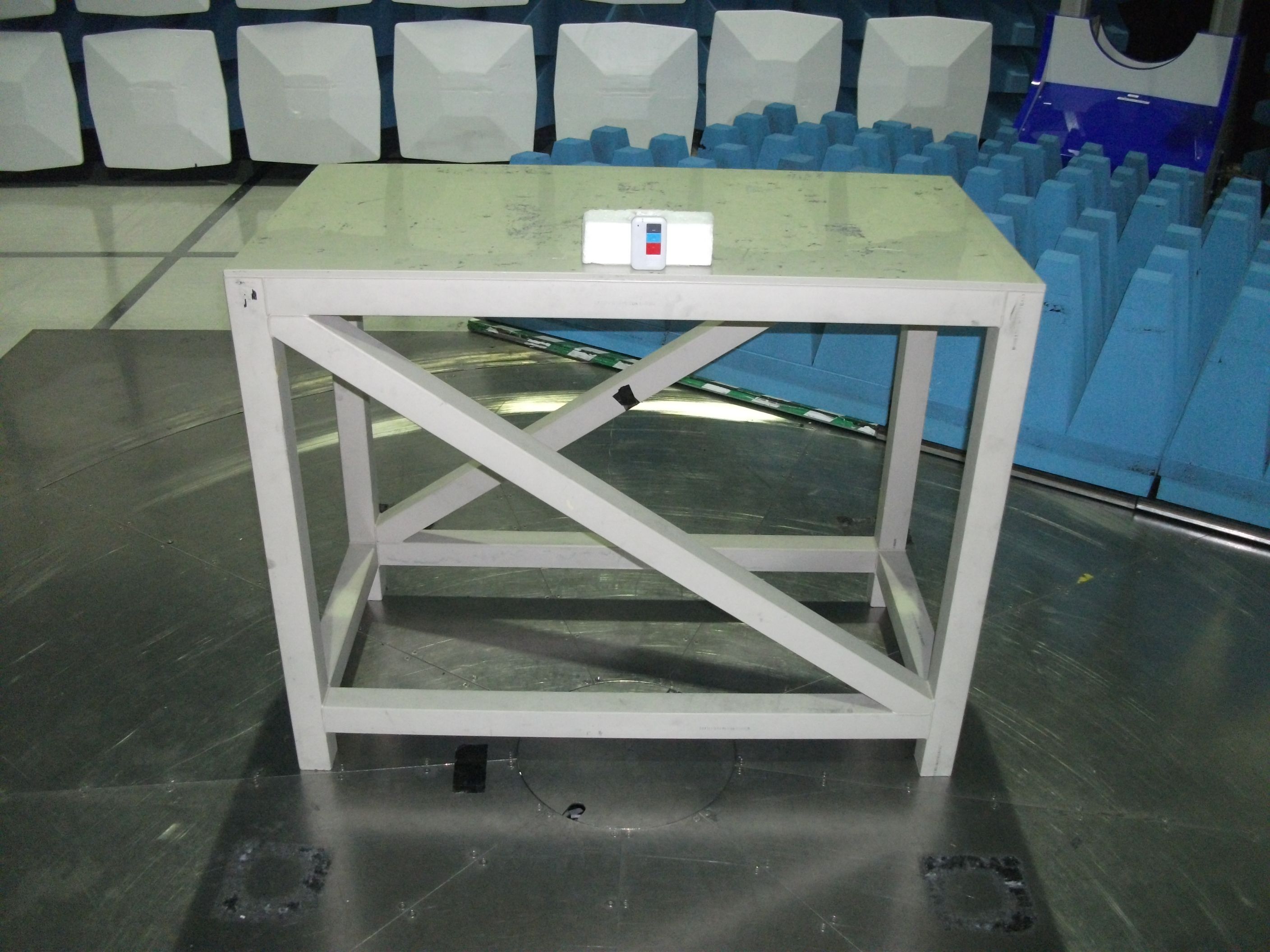
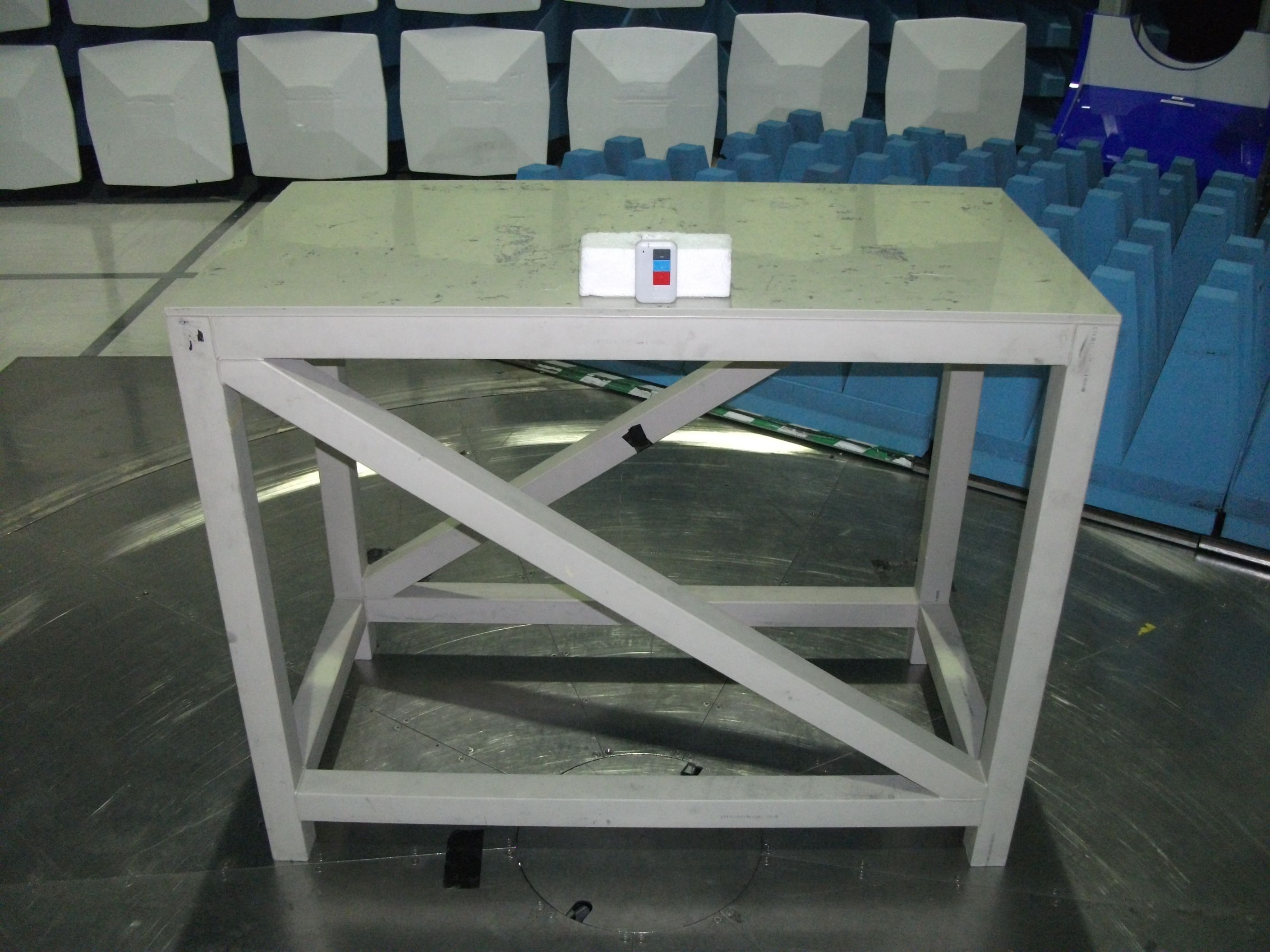
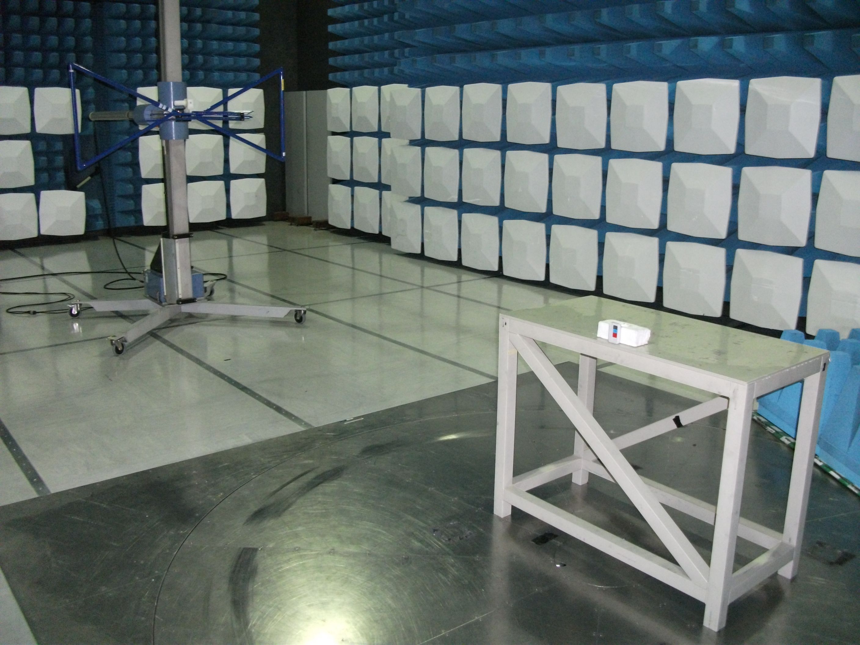
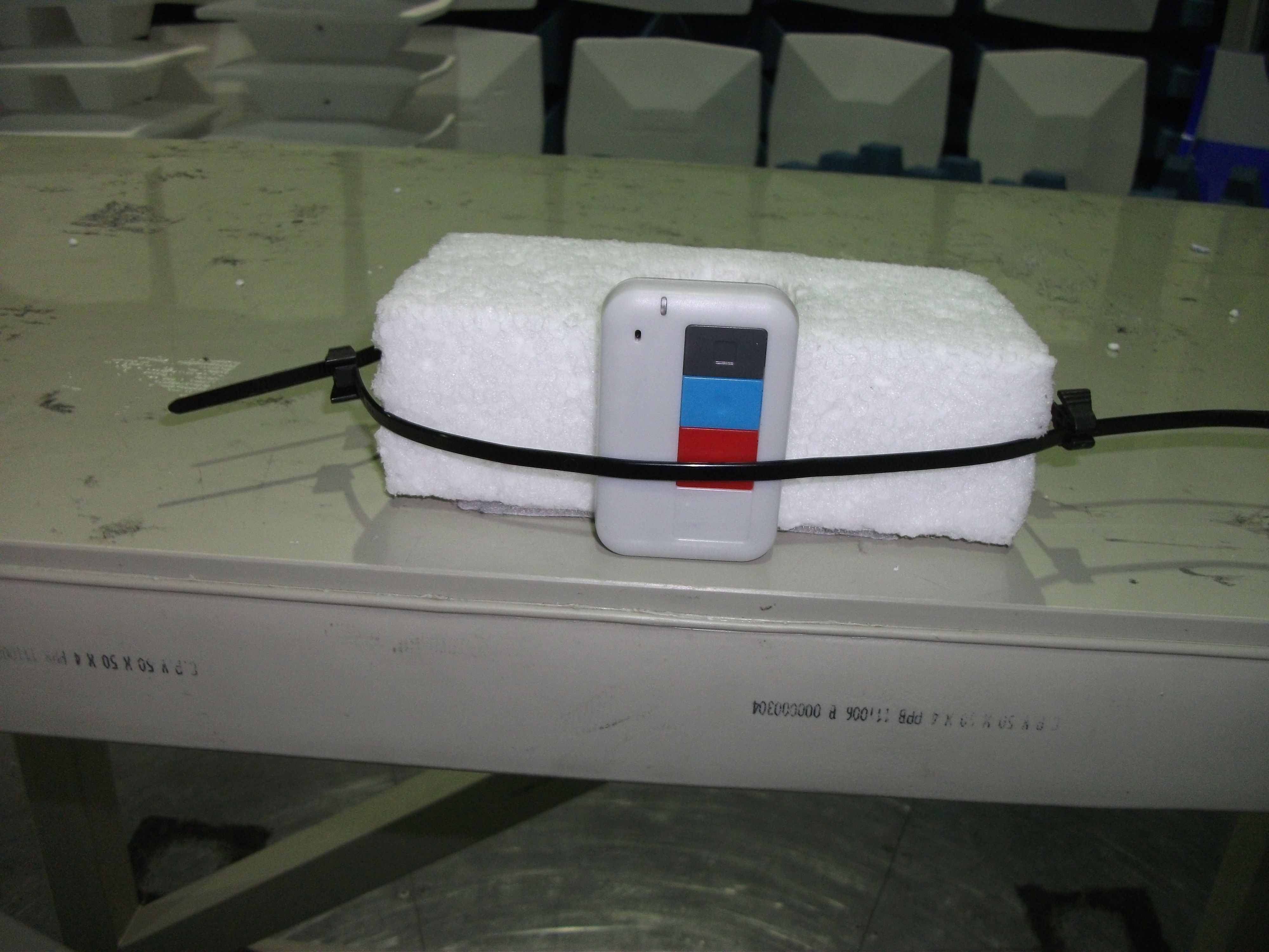
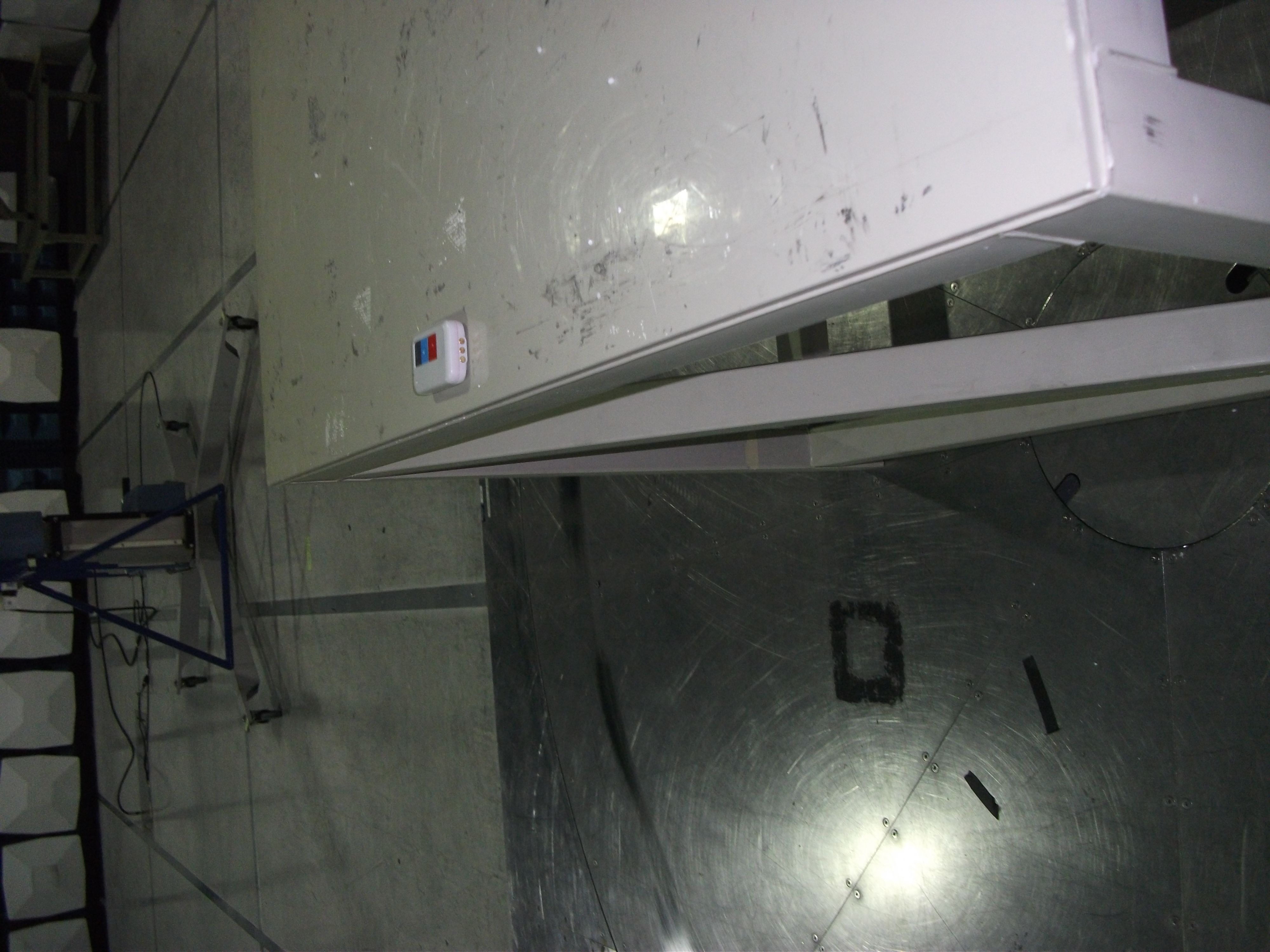
Multitone Electronics plc, Multitone House, Shortwood Copse Lane, Kempshott, Basingstoke, Hampshire, RG23 7NL Telephone: +44 (0)1256 320292 Fax: +44 (0)1256462643 Email: [email protected] Web: www.multitone.com Registered in England & Wales No. 256314. Registered VAT No: GB 232150709. FM 20122 Federal Communications Commission, 7435 Oakland Mills Road, Columbia, MD 21046 USA 26th March 2013 Response to e-mail 12/03/2013 Ref. EA662618 Multitone EkoTek FOB - E86EKOFOB Dear Sir/Madam, In reply to your e-mail ref. our submission, I offer the following responses:- 1. I have now located some pictures taken during the test process. These have now been uploaded as requested. 2. I did not realise that a separate letter was required to request short term confidentiality; I assumed it was automatic until approval had been granted. Please ignore this request. I trust that the information supplied is sufficient to cover your requirements, but if you need any further please do not hesitate to contact me. Yours sincerely, B.R. Merchant, Principal Approvals Engineer, Multitone Electronics plc Telephone: - +44 1256 320292/ (direct) 845148 e-mail: - [email protected]
Internal Photos
EKOFOB – General Internal View EKOFOB – PCB Topside EKOFOB – PCB Underside
Operational Description
CC2530F32, CC2530F64 CC2530F128, CC2530F256 www.ti.comSWRS081B–APRIL2009–REVISEDFEBRUARY2011 A TrueSystem-on-ChipSolutionfor2.4-GHzIEEE802.15.4andZigBeeApplications CheckforSamples:CC2530F32, CC2530F64, CC2530F128, CC2530F256 1 FEATURES –IEEE802.15.4MACTimer,General-Purpose Timers(One16-Bit,Two8-Bit) 2345 •RF/Layout –IRGenerationCircuitry –2.4-GHzIEEE802.15.4CompliantRF Transceiver–32-kHzSleepTimerWithCapture –ExcellentReceiverSensitivityand–CSMA/CAHardwareSupport RobustnesstoInterference –AccurateDigitalRSSI/LQISupport –ProgrammableOutputPowerUpto4.5dBm –BatteryMonitorandTemperatureSensor –VeryFewExternalComponents –12-BitADCWithEightChannelsand –Onlya SingleCrystalNeededforConfigurableResolution AsynchronousNetworks –AESSecurityCoprocessor –6-mm×6-mmQFN40Package –TwoPowerfulUSARTsWithSupportfor –SuitableforSystemsTargetingComplianceSeveralSerialProtocols WithWorldwideRadio-Frequency –21General-PurposeI/OPins Regulations:ETSIEN300328andEN300 (19×4 mA,2×20mA) 440(Europe),FCCCFR47Part15(US)and –WatchdogTimer ARIBSTD-T-66(Japan) •DevelopmentTools •LowPower –CC2530DevelopmentKit –Active-ModeRX(CPUIdle):24mA –CC2530ZigBee ® DevelopmentKit –ActiveModeTXat1 dBm(CPUIdle):29mA –CC2530RemoTI™DevelopmentKitfor –PowerMode1 (4μs Wake-Up):0.2mA RF4CE –PowerMode2 (SleepTimerRunning):1μA –SmartRF™Software –PowerMode3 (ExternalInterrupts):0.4μA –PacketSniffer –WideSupply-VoltageRange(2V–3.6V) –IAREmbeddedWorkbench™Available •Microcontroller –High-PerformanceandLow-Power8051APPLICATIONS MicrocontrollerCoreWithCodePrefetch •2.4-GHzIEEE802.15.4Systems –32-,64-,128-,or256-KB •RF4CERemoteControlSystems(64-KBFlash andHigher) In-System-ProgrammableFlash •ZigBeeSystems(256-KBFlash) –8-KBRAMWithRetentioninAllPower •Home/BuildingAutomation Modes •LightingSystems –HardwareDebugSupport •IndustrialControlandMonitoring •Low-PowerWirelessSensorNetworks •Peripherals •ConsumerElectronics –PowerfulFive-ChannelDMA •HealthCare –IntegratedHigh-PerformanceOp-Ampand Ultralow-PowerComparator 1 Pleasebeawarethatanimportantnoticeconcerningavailability,standardwarranty,andusein criticalapplicationsofTexas Instrumentssemiconductorproductsanddisclaimerstheretoappearsattheendofthisdatasheet. 2RemoTI,SmartRF,Z-StackaretrademarksofTexasInstruments. 3IAREmbeddedWorkbenchis a trademarkofIARSystemsAB. 4ZigBeeis a registeredtrademarkoftheZigBeeAlliance. 5Allothertrademarksarethepropertyoftheirrespectiveowners. PRODUCTIONDATA…
Text truncated - open the document above for the full version.
Contact Information
Applicant
B. R. Merchant(Principal Approvals Engineer)
Technical Contact
Multitone Electronics plcBrian Ronald Merchant
[email protected]+44 1256845148
Multitone House · Basingstoke · United Kingdom
Test Firm
UL VS LtdDarren Rust
Technical Specifications
| # | Rule Parts | Frequency Range | Power Output |
|---|---|---|---|
| 1 | 15C | 2.40 GHz - 2.48 GHz | 10.00 mW |
Other Applications from Multitone Electronics PLC
E86EKOCPLVRM
Feb 26, 2026EKOTek call point
Equipment Class
DTS - Digital Transmission System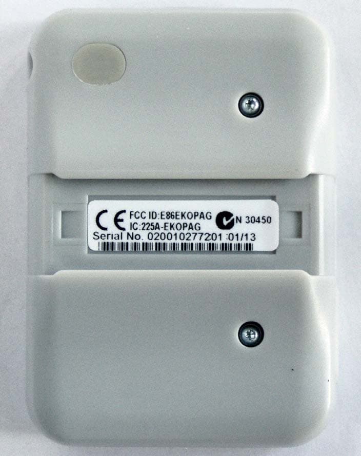
E86EKOPAG
Apr 02, 2013Alpha-numeric 2 way alarm and paging device
Equipment Class
DTS - Digital Transmission System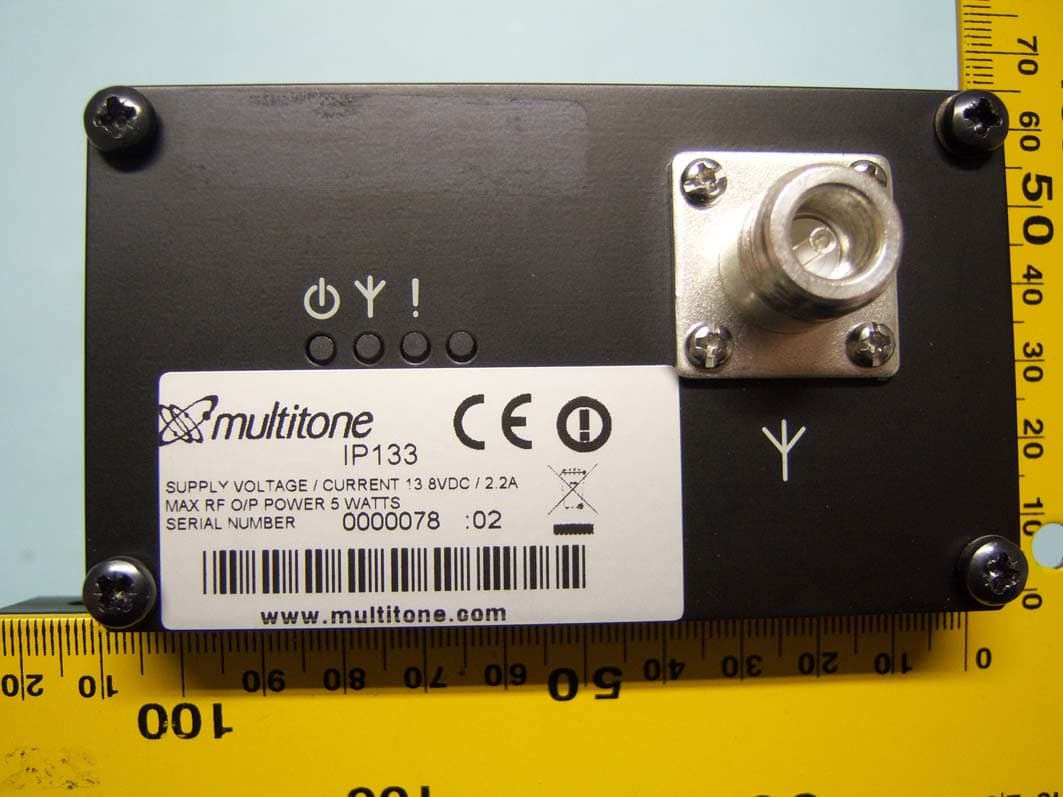
E86IP133
Feb 07, 2012Multitone I-Page � IP133
Equipment Class
TNB - Licensed Non-Broadcast Station TransmitterE86RPT503
Aug 07, 2008UHF Paging Transmitter
Equipment Class
TNB - Licensed Non-Broadcast Station Transmitter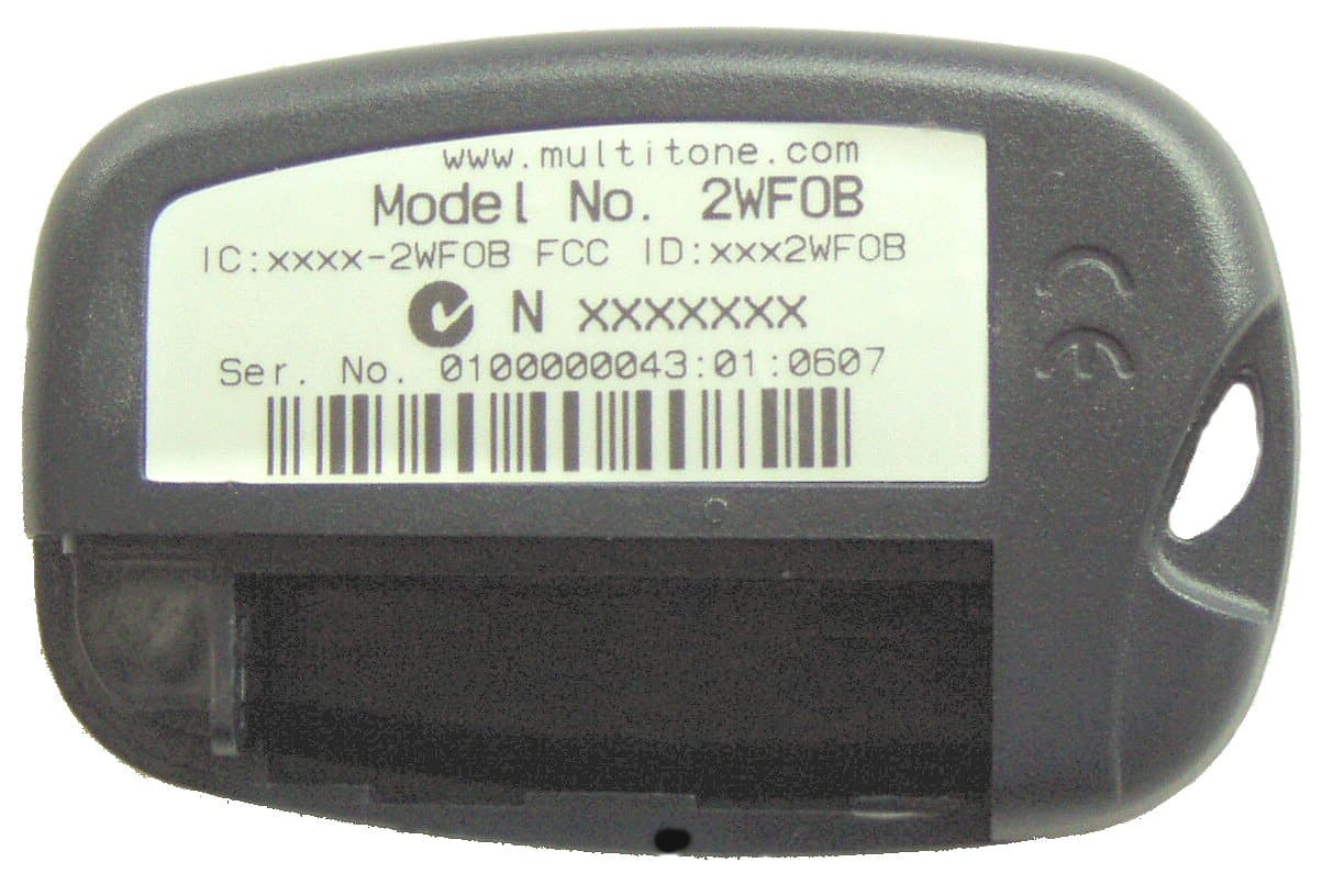
E862WCF
Nov 04, 2007EkoTek FOB - 2 way alerting device
Equipment Class
DTS - Digital Transmission System