E86IP133Multitone I-Page � IP133
Multitone Electronics PLC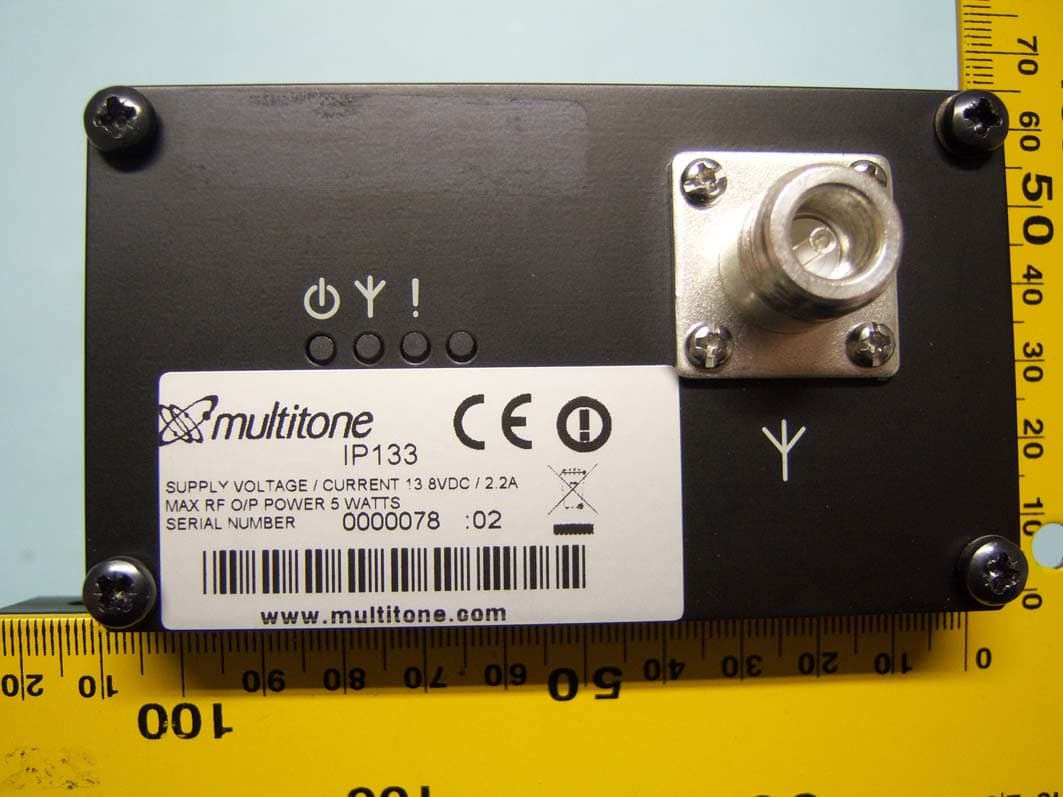
Click to zoom
Application Details
- Equipment Class
- TNB - Licensed Non-Broadcast Station Transmitter
- Date of Grant
- Feb 07, 2012
- Application Purpose
- Original Equipment
- Date of Application
- Feb 07, 2012
- Equipment Note
- Multitone I-Page � IP133
- Frequency Range
- 438.00000000 - 470.00000000
- Company
- Multitone Electronics PLC
- Country
- United Kingdom
Documents & Files
Document Text
Text extracted from the exhibit documents filed with the FCC. Open a document above to read the original.
Users Manual
Multitone i-Page User and Installation Guide ISSUE CONTROL Issue Date Remarks 01 01.08.11 First Issue 02 25.10.11 Grammatical changes, removal of some pager images and addition of waterproof pager i-Page USER AND INSTALLATION GUIDE Index of contents Important User Information Section Description Page 1.0 Checking supplied equipment 2 2.0 Tools 2 3.0 Equipment required 2 4.0 Assembly requirements 3 4.1 Assembly 3 4.2 Mounting 3 4.3 Power supply 3 4.4 Network cable 4 4.5 Aerial fitting 4 5.0 i-Page setup 4 5.1 i-Page network setup – Changing IP address for use on local network 5 5.2 IP Settings - Set static IP address, Netmask, gateway, Syslog for i-Page 5 5.3 Language - Select browser and pager languages 6 5.4 Clock - Set time and date 6 5.5 Paging setup - Set system address, paging format, time on/off, message 7 length and coverage test 5.6 Password - Set one administrator or five user passwords 7 5.7 Users - Add, amend or delete users 7 5.8 Groups - Add and remove groups 8 5.9 Stored Messages - Add or remove stored messages up to 80 characters 8 5.10 DLC’s - Programme DLC alarm details 9 5.11 Serial port - Select serial port protocol 9 5.12 Backup/Restore - Backup and restore i-Page data 10 5.13 Factory reset - Reset i-Page to factory setting. Note that all system data is 10 destroyed 6.0 Engineering button – Temporarily restore default IP address 10 7.0 Paging users and groups - User interface for paging users and groups 11 7.1 Logout - Used to log out of Multitone i-Page 11 8.0 Syslog message tracking – Optional software form logging messages 11 9.0 Transmitter alignment – Changing the transmitter frequency 11 10.0 Software upgrades – Updating i-Page 12 Appendices Appendix 1 DLC alarm and serial port technical requirements 14 Appendix 2 Frequently asked questions and fault finding 15 Appendix 3 i-Page specifications 16 Appendix 4 Multitone Pagers 17 Appendix 5 i-Page Spares 18 IMPORTANT USER INFORMATION CAUTION THIS PRODUCT HAS NO REPLACEABLE COMPONENTS. ALL FAULTY UNITS SHOULD BE RETURNED TO MULTITONE OR THEIR AGENT, FOR REPAIR. FOR AVAILABLE SPARE PARTS, SEE APPENDIX 6. STATIC SENSITIVE DEVICES ARE USED WITHIN THIS EQUIPMENT. OBSERVE STATIC SAFETY PRECAUTIONS IF CHANGING COMPONENTS. ENSURE THE UNIT IS MOUNTED IN A DRY ENVIRONMENT, BUT NOT OVER A HEAT SOURCE OR IN DIRECT SUNLIGHT. WEEE DIRECTIVE & PRODUCT DISPOSAL At the end of its serviceable life, this product should not be treated as household or general waste. It should be handed over to the applicable collection point for the recycling of electrical and electronic equipment, or returned to Multitone or their agent, for disposal. Company Liability The information in this manual has been carefully compiled and checked for technical accuracy. Multitone Electronics plc accepts no liability for inaccuracies or errors. In line with the company policy of technical advancement, the information within this document may be changed. The user should ensure that the correct issue of the document is used. Comments or correspondence regarding this manual should be addressed to: Safety Summary Important Safety Information The Multitone i-Page IP133 Radio Paging Transcoder equipment, contains a low power (5 Watts) radio transmitter and is intended for use with either an externally mounted dipole antenna, or a “local” unity gain (or less) "desk-top" whip antenna. The equipment’s performance may be characterized in accordance with the recommended MPE requirements of the European Council Directive 1999/519/EC on the limitation of exposure of the general public to electromagnetic fields (0Hz - 300GHz), as given in Annex III, Table 2; the requirements of FCC 47CFR and Industry Canada Standard RSS102. Where an installation is to be fitted with a "local" whip style antenna, the following criteria must be adhered to, in order to reduce and comply with the Electro-magnetic radiation absorption regulations. Multitone Electronics plc Technical Publications Hansa Road Hardwick Industrial Estate Kings Lynn Norfolk PE30 4HX Englan NOTE: Any equipment and antenna that is installed within an area normally populated whilst it is in use, must be located in a position where people may not approach, or be located within 1m of the radiating antenna, for periods in excess of 5 mins. in any 1 hour. This distance is calculated to include an additional safety margin for the product. Compliance Information EU Territories - This product complies with the requirements of the EU Radio & Telecommunications Terminal Equipment Directive 99/5/EC. A complete copy of the associated Declaration of Conformity for this and other Multitone products may be found at the Multitone Internet address www.multitone.com. This is Class 2 type equipment under the terms of the R & TTE Directive and is therefore subject to restrictions in its use. Before installation and use, consult your local radio communications spectrum authority, for licensing and frequency regulations. US & Canada - This product has been tested and certified for use in both the US and Canada. Any modifications to this equipment not expressly authorised by Multitone, could void the user's authority to operate the equipment. (The term "IC:" before the certification/registration number, only signifies that the Industry Canada technical specifications were met.) Installation Notes The equipment should be positioned so that there is no interference to the flow of air around the unit and away from sources of heat. It should only be mounted to a wall, as recommended in the installation instructions. Care must be taken during installation to keep the power supply away from excessive RF fields. Where the transmitter power is to be greater than 2.5W, the antenna must be sited a minimum of 1.5 metres away from the IP133 housing and power supply. In cases where a close-coupled antenna must be used, the transmitter power must be reduced to a maximum of 2.5W and care must be taken to position the antenna at least 0.5m from the power sup…
Text truncated - open the document above for the full version.
Users Manual
Multitone i-Page User and Installation Guide ISSUE CONTROL Issue Date Remarks 01 01.08.11 First Issue 02 25.10.11 Grammatical changes, removal of some pager images and addition of waterproof pager i-Page USER AND INSTALLATION GUIDE Index of contents Important User Information Section Description Page 1.0 Checking supplied equipment 2 2.0 Tools 2 3.0 Equipment required 2 4.0 Assembly requirements 3 4.1 Assembly 3 4.2 Mounting 3 4.3 Power supply 3 4.4 Network cable 4 4.5 Aerial fitting 4 5.0 i-Page setup 4 5.1 i-Page network setup – Changing IP address for use on local network 5 5.2 IP Settings - Set static IP address, Netmask, gateway, Syslog for i-Page 5 5.3 Language - Select browser and pager languages 6 5.4 Clock - Set time and date 6 5.5 Paging setup - Set system address, paging format, time on/off, message 7 length and coverage test 5.6 Password - Set one administrator or five user passwords 7 5.7 Users - Add, amend or delete users 7 5.8 Groups - Add and remove groups 8 5.9 Stored Messages - Add or remove stored messages up to 80 characters 8 5.10 DLC’s - Programme DLC alarm details 9 5.11 Serial port - Select serial port protocol 9 5.12 Backup/Restore - Backup and restore i-Page data 10 5.13 Factory reset - Reset i-Page to factory setting. Note that all system data is 10 destroyed 6.0 Engineering button – Temporarily restore default IP address 10 7.0 Paging users and groups - User interface for paging users and groups 11 7.1 Logout - Used to log out of Multitone i-Page 11 8.0 Syslog message tracking – Optional software form logging messages 11 9.0 Transmitter alignment – Changing the transmitter frequency 11 10.0 Software upgrades – Updating i-Page 12 Appendices Appendix 1 DLC alarm and serial port technical requirements 14 Appendix 2 Frequently asked questions and fault finding 15 Appendix 3 i-Page specifications 16 Appendix 4 Multitone Pagers 17 Appendix 5 i-Page Spares 18 IMPORTANT USER INFORMATION CAUTION THIS PRODUCT HAS NO REPLACEABLE COMPONENTS. ALL FAULTY UNITS SHOULD BE RETURNED TO MULTITONE OR THEIR AGENT, FOR REPAIR. FOR AVAILABLE SPARE PARTS, SEE APPENDIX 6. STATIC SENSITIVE DEVICES ARE USED WITHIN THIS EQUIPMENT. OBSERVE STATIC SAFETY PRECAUTIONS IF CHANGING COMPONENTS. ENSURE THE UNIT IS MOUNTED IN A DRY ENVIRONMENT, BUT NOT OVER A HEAT SOURCE OR IN DIRECT SUNLIGHT. WEEE DIRECTIVE & PRODUCT DISPOSAL At the end of its serviceable life, this product should not be treated as household or general waste. It should be handed over to the applicable collection point for the recycling of electrical and electronic equipment, or returned to Multitone or their agent, for disposal. Company Liability The information in this manual has been carefully compiled and checked for technical accuracy. Multitone Electronics plc accepts no liability for inaccuracies or errors. In line with the company policy of technical advancement, the information within this document may be changed. The user should ensure that the correct issue of the document is used. Comments or correspondence regarding this manual should be addressed to: Safety Summary Important Safety Information The Multitone i-Page IP133 Radio Paging Transcoder equipment, contains a low power (5 Watts) radio transmitter and is intended for use with either an externally mounted dipole antenna, or a “local” unity gain (or less) "desk-top" whip antenna. The equipment’s performance may be characterized in accordance with the recommended MPE requirements of the European Council Directive 1999/519/EC on the limitation of exposure of the general public to electromagnetic fields (0Hz - 300GHz), as given in Annex III, Table 2; the requirements of FCC 47CFR and Industry Canada Standard RSS102. Where an installation is to be fitted with a "local" whip style antenna, the following criteria must be adhered to, in order to reduce and comply with the Electro-magnetic radiation absorption regulations. Multitone Electronics plc Technical Publications Hansa Road Hardwick Industrial Estate Kings Lynn Norfolk PE30 4HX Englan NOTE: Any equipment and antenna that is installed within an area normally populated whilst it is in use, must be located in a position where people may not approach, or be located within 1m of the radiating antenna, for periods in excess of 5 mins. in any 1 hour. This distance is calculated to include an additional safety margin for the product. Compliance Information EU Territories - This product complies with the requirements of the EU Radio & Telecommunications Terminal Equipment Directive 99/5/EC. A complete copy of the associated Declaration of Conformity for this and other Multitone products may be found at the Multitone Internet address www.multitone.com. This is Class 2 type equipment under the terms of the R & TTE Directive and is therefore subject to restrictions in its use. Before installation and use, consult your local radio communications spectrum authority, for licensing and frequency regulations. US & Canada - This product has been tested and certified for use in both the US and Canada. Any modifications to this equipment not expressly authorised by Multitone, could void the user's authority to operate the equipment. (The term "IC:" before the certification/registration number, only signifies that the Industry Canada technical specifications were met.) Installation Notes The equipment should be positioned so that there is no interference to the flow of air around the unit and away from sources of heat. It should only be mounted to a wall, as recommended in the installation instructions. Care must be taken during installation to keep the power supply away from excessive RF fields. Where the transmitter power is to be greater than 2.5W, the antenna must be sited a minimum of 1.5 metres away from the IP133 housing and power supply. In cases where a close-coupled antenna must be used, the transmitter power must be reduced to a maximum of 2.5W and care must be taken to position the antenna at least 0.5m from the power sup…
Text truncated - open the document above for the full version.
Attestation Statements
Multitone Electronics plc is part of Kantone Holdings Ltd, a member of the Champion Technology group of companies. Registered office: Multitone Electronics plc, Shortwood Copse Lane, Kempshott, Basingstoke, Hampshire, RG23 7NL. Registered in England No. 256314. Multitone Electronics plc Multitone House Shortwood Copse Lane Kempshott, Basingstoke Hampshire, RG23 7NL Tel: +44 (0)1256 320292 Fax: +44 (0)1256 462643 Email: [email protected] Web: www.multitone.com Cert No. FM20122 2 nd February 2012 TRaC Global 100 Frobisher Business Park Leigh Sinton Road Malvern Worcestershire WR14 1BX UK To Whom It May Concern: We certify that we are not subject to denial of federal benefits, that includes FCC benefits, pursuant to Section 5301 of the Anti-Drug Abuse ACT of 1988, U.S.C. 862. Further, no party, as defined in 47 CFR 1.2002(b), to the application, is subject to denial of federal benefits, that includes FCC benefits. Thank you for your attention to this matter. Yours faithfully, Principal Approvals Eng. Multitone Electronics plc
Block Diagram
13MHz VCTCXO XL7 3.3V IC4 S y nthesise r Line S y nc Frequency Control Voltage VCO 430 – 470MHz TR28 Buffer TR26,TR27 Amplifier IC28 Loop Filter Processo r Driver IC44 Power Amplifier PM1 Power Monitor Processo r RF Out p u t RF Circuit Block Diagram 5V 5V 5V 5V 13.8V 13.8V Lock Detect TR12, TR13 Processo r Modulation from IC46B
ID Label/Location Info
2061-8862 P.McMullan 18.5.11 Full Size See drawing. Make from Pt. No. 2004-0021 2061-8862 c Title Drawn Checked Approved Approved Drg. No. Sheet 1 of 1 Z Name Date Third angle projection Scale Dimensions in mm D C B Finish Material Tolerances Unless stated otherwise 0.4 to 1 decimal place 0.2 to 2 decimal places Angles 1 / 2 o 0.1 to 3 decimal places Holes + 0.05 up to 5 1% above Concentricity to within 0.1 diameter All threads to BS3643 pt2 1981 class 6H-6g A 5 Issue Amendment Date A Introduced Do not scale drawing 3 4 1 2 Drg. No. Sheet1 of 1 Z A B C D Equipment Label IP13X Series(i-Page) Reproduced or disclosed to a third party without written consent Reserve the Copyright of this drawing which is not to be copied Multitone Electronics plc 57.00 28.00 NOTES 1. Label environmental requirements to comply with environmental Test Spec. G006 Issue 2 sections ‘Climatic Operations & Test’ & ‘Climatic Operations for Labels’. 2. Labels should have an easy peel off protective backing on adhesive side. 3. Labels to be free from imperfections. 4. For artwork see Drawing No. 1961-8863 MATERIAL: Silver metalalised Polyester Film total thickness 0,076mm. ADHESIVE: Permanent High Performance Acrylic FINISH: Text and symbols to be printed Black 3.00 1.60 B.R.Merchant J. Curtis T.Hunt Reproduced or disclosed to a third party without written consent Reserve the Copyright of this drawing which is not to be copied Multitone Electronics plc 2011 Uncontrolled when printed Variable information This Part Must be Supplied RoHS Compliant RoHS COMPLIANT 18.5.11 Code 39 Bar Code 18.5.11 18.5.11 18.5.11 1 Prod Issue 26.10.11 2 CN 12339 27.10.11
Operational Description
RPT503 Circuit Description DRAFT To be read with reference to drawing 2961-7866. Multiple ICs (quad op amps, multiple logic gates etc.) are denoted in this description by their output pin. E.g. IC32 (pin 8) is the operational amplifier comprising pins 9 and 10 inputs and pin 8 output. Sheet 1 XL7 is the main reference oscillator for the transmitter. It operates at 13.000MHz. Stability is 2ppm from –25 to +55 deg C and output is 0.8V p-p clipped sine. The low frequency component of the data modulation is applied to the control input on pin 1. This gives FSK modulation. Three eepots are used to set various frequencies: 1. IC53A sets FSK frequency for data level high 2. IC53B sets FSK frequency for data level low 3. IC52A sets centre frequency for analogue modulation. IC64 routes the data (DATA-A) to the appropriate eepot depending on the level of the mode line (A/D.) The three potentiometers apply dc levels to buffer amplifier IC61. The output from this stage feeds the control input of the reference oscillator XL7 via low pass filter IC62. The position of the eepot slider is governed by the microcontroller IC60 on sheet 3 Sheet 2 The circuits of sheet 2 control the high frequency component of the modulation. IC46B sets the level for the high frequency component of the data modulation. This will also effect the analogue modulation, so data modulation must be adjusted before the analogue modulation is set up. IC32 (pin 8) is a buffer amplifier. IC32 (pin 7) is a combiner which combines the data modulation from IC31 (pin7) and the analogue modulation from IC46A. Audio (analogue) from sheet 3 passes through low pass filter circuit IC32 (pin1) and then eepot IC46A which sets the analogue modulation limiting level. Data (DATA-B) from sheet 3 is split into the high and low frequency paths. High frequency path passes through IC18 (pin3) and IC31 (pin1) which convert the signal from logic to analogue levels. IC31 (pin7) is a low pass filter which sets the modulated data rise time. Low frequency path passes through IC33 (pin 3), which is set by R181 as a buffer. If R158 is fitted instead of R181, then this stage would invert. IC66 together with IC67 delay the data in the low frequency path so that it reaches the modulator at the same time as the high frequency component. Sheet 3 The circuits of sheet 3 are the interface and controller circuits. IC60 is the microcontroller which carries out the “housekeeping” for the transmitter. It sets up synthesizer and eepot values as well as monitoring levels and error conditions. It communicates with the outside world via RS232 interface IC58 which connects to a PC for setup purposes. SK8 is the line interface connector for modulation/control and for line synchronisation. 600 ohm line input from the encoder passes through isolating transformer T3 to level adjuster circuit IC8 (pin 14.) Line input level is set by eepot IC45a. IC31 (pin 8) with diodes D43 and capacitor C310 form a rectifier which monitors the line input level. IC31 (pin14) forms a buffer which feeds the line level signal to a D/A converter in IC60. The line level can thus be monitored on a connected PC in order to adjust eepot IC45a to the correct value. IC8 (pin 1), D42, TR21 and TR22 form the vox circuit. The vox key signal is connected to Micro IC60. Eepot IC45b is used to set the speech (analogue) modulation level. IC8 (pin 7) is the pre-emphasis circuit. IC8 (pin 8) is a unity gain buffer. IC3 is a switched capacitor low pass filter which limits the bandwidth of the speech modulation. The cut off point is determined by the clock frequency which is set by capacitors C144 and C145. C145 lowers the cut off point and is fitted for 12.5kHz bandwidth. Cut off frequencies are set at 3kHz for 25kHz bandwidth and 2.5kHz for 12.5kHz bandwidth. Audio output from IC3 goes to sheet 2. IC19 is a 1200bd modem to demodulate data from the line input. IC18 (pin 8) ensures that only valid data is presented to IC33 (pin 6.) IC33 (pin 6) selects data polarity. When pin 5 is high the data is inverted in IC33 (pin 6.) When pin 5 is low data is fed through unchanged. The output from the polarity selector goes to sheet 2 (DATA-B.) IC23 is the DTMF detector which decodes the DTMF transmitter control codes from the line input. These are interpreted by microcontroller IC60. TR24 and TR25 interface and protect the external key and mode lines. TR23 feeds the external error line. Connector PL1 is the interface to the internal encoder (RPE500) if fitted. Connector SK1 is the auxiliary connector. This is used for: 1. Flash programming the microcontroller 2. Programming and adjusting the transmitter over the RS232 interface from a PC. 3. External direct data, mode and key lines. 4. Error output (single open collector.) Sheet 4 The circuits on sheet 4 are the main synthesizer. Reference signal, 13MHz, is from sheet 1. IC4 is the synthesizer system and comprises dividers and a phase detector. Values for a particular channel are loaded from the microcontroller IC60 on start up. C104, C311, C110, C111, R68 and R70 comprise the loop filter. R67 aids fast lock up. IC68 is a buffer amplifier which feeds the loop control voltage to microcontroller IC60 so that it can be monitored during set up. TR28 is the low noise VCO. Frequency is set by tuned line L1, CV1 and variable capacitance diodes D18 for loop feedback and D47 for modulation. TR26 and TR27 are a cascade buffer amplifier. The output from the buffer is split in R133, R134 and R135. Part is fed back to the synthesizer IC4 to close the loop. The other part is fed to pre-driver IC28. IC28 has a gain of about 15dB and produces the RF DRIVE signal to sheet 5. IC35 and IC37 are switched regulators, each providing switched 5V supplies to their respective circuits. R106 and C108 filter the out of lock signal to TR12 and TR13 which drives the out of lock LED and signal back to IC60. Sheet 5 The circuits of sheet 5 are the amplifiers which raise the signal level up to the 5 watts outp…
Text truncated - open the document above for the full version.
Parts List/Tune Up Info
Bill of Material Report Multitone Electronics Plc Indented Level Page: 1 Date: 07/02/2012 Time: 14:09:32 User: bmerchant Part Number Lvl Seq Revision Description Typ Qty/Parent Description Ref Des 1 IP123 PBA-Transmitter UHF - Bo 0201-1337-BOM 1 1.00 1 A sm 10 .0301-1426 SMA IP123 EA 1 1.00 1 Mtl 20 .0961-8858 End Plate RF EA 1 1.00 1 Mtl 30 .1061-8137 Bracket EA 2 2.00 1 Mtl 40 .1061-8296 Bracket RPT500 EA 2 1.00 1 Mtl 50 .1161-7930 HEATSINK RPT500 EA 1 1.00 1 Mtl 60 .1261-8138 Screen Can VCO EA 2.00 1 Mtl 70 .19663 NUT M3 FULL S/S EA 1.00 1 Mtl 80 .2334-0001 LIGHT PIPE 4 WAY EA 6.00 1 Mtl 90 .24573 SCREW M3X8 PAN HD POZI S/S :02 EA 8.00 1 Mtl 100 .24624 SCREW M2.5X6MM PAN HD POZI EA 0 1.00 1 Mtl 110 .3502-0002 CAP CHIP VAR 3-10P TOP ADJ EA 0 1.00 1 Mtl 120 .3823-0026 RF MOSFET AMP. RA07H4047M EA 1 1.00 1 Mtl 130 .4161-8120 VCO Inductor EA 0 1.00 1 Mtl 140 .4403-0038 SOCKET D TYPE 15 WAY PCB R/A EA 0 1.00 1 Mtl 150 .4413-0001 SKT N TYPE COAX 50 OHM EA 0 1.00 1 Mtl 160 .4456-0002 SOCKET DC POWER 2.1MM PIN EA 0 1.00 1 Mtl 170 .4478-0008 SOCKET SIL 0.64" SQ. 8 WAY EA 0 0.01 1 Mtl 180 .9408-0003 HEATSINK COMPOUND EA Bill of Material Report Multitone Electronics Plc Indented Level Page: 1 Date: 07/02/2012 Time: 14:07:50 User: bmerchant Part Number Lvl Seq Revision Description Typ Qty/Parent Description Ref Des 1 i-Page Encoder PBA 0261-8699-BOM 1 1.00 1 A sm 10 .0301-1495 i-Page Encoder SMA EA 0 1.00 1 Mtl 20 .3331-0004 CAP 0.1F 5.5V EA 0 1.00 1 Mtl 30 .4202-0024 SWITCH 90DEG. EA 0 1.00 1 Mtl 40 .4302-0040 PLUG DTYPE 15 WAY HD PCB MOUNT EA 0 1.00 1 Mtl 50 .4320-0004 9WAY D TYPE PLUG, RL EA 0 1.00 1 Mtl 60 .4335-0009 HEADER, 2 x 10 WAY EA 0 1.00 1 Mtl 70 .4344-0008 PLUG PIN HEADER 8 WAY 0.64mmSQ EA 1 1.00 1 Mtl 80 .4401-0036 RJ45 Socket SMD + LEDS (G+Y) EA Bill of Material Report Multitone Electronics Plc Indented Level Page: 1 Date: 07/02/2012 Time: 14:25:09 User: bmerchant Part Number Lvl Seq Revision Description Typ Qty/Parent Description Ref Des 1 i-Page Encoder SMA 0301-1495-BOM 1 1.00 1 Mtl 10 .3061-8700 PCB: I-PAGE Encoder EA 0 9.00 1 Mtl 20 .3115-0050 RES CHIP 100R 5% 62M5W EA 0 4.00 1 Mtl 30 .3115-0062 RES, CHIP 330R 5% 62M5W EA 0 14.00 1 Mtl 40 .3115-0066 RES CHIP 470R 5% 62M5W EA 0 1.00 1 Mtl 50 .3115-0078 RES CHIP 1K5 5% 62M5W EA 0 1.00 1 Mtl 60 .3115-0082 RES CHIP 2K2 5% 62M5W EA 0 28.00 1 Mtl 70 .3115-0098 RES CHIP 10K 5% 62M5W EA 0 1.00 1 Mtl 80 .3115-0102 RES CHIP 15K 5% 62M5W EA 0 14.00 1 Mtl 90 .3115-0122 RES CHIP 100K 5% 62M5W EA 0 4.00 1 Mtl 100 .3129-0001 RES CHIP 49R9 1% 0.1W 0603 EA 0 1.00 1 Mtl 110 .3129-0004 RES CHIP 12K4 1% 0.1W 0603 EA 0 2.00 1 Mtl 120 .3301-0362 CAP CHIP 0805 4.7UF 10% 6.3V EA 0 1.00 1 Mtl 130 .3306-0015 CHIP CAP TANT 10UF 16V EA 0 1.00 1 Mtl 140 .3306-0033 CAP CHIP TANT 220uF 20% 10V EA 0 1.00 1 Mtl 150 .3306-0038 CAP CHIP TANT 33uF 20% 35V EA 0 4.00 1 Mtl 160 .3326-0015 CAP, CHIP 10P 0P5 50V EA 0 4.00 1 Mtl 170 .3326-0018 CAP CHIP 18PF 5% 50V EA 0 10.00 1 Mtl 180 .3326-0027 CAP CHIP 100P 5% 50V EA 0 2.00 1 Mtl 190 .3326-0032 CAP CHIP 270P 5% 50V EA 0 17.00 1 Mtl 200 .3327-0013 CAP CHIP 1N0 10% 50V EA 0 2.00 1 Mtl 210 .3327-0021 CAP CHIP 4N7 10% 50V EA 0 10.00 1 Mtl 220 .3327-0025 CAP CHIP 10N 10% 50V EA 0 5.00 1 Mtl 230 .3327-0029 CAP CHIP 0603 100nF 10% 50V EA 0 1.00 1 Mtl 240 .3329-0013 CAP CHIP 100NF +80-20% 16V EA 0 9.00 1 Mtl 250 .3332-0014 CAP CHIP 100nF 10% 10V 0603 EA 0 3.00 1 Mtl 260 .3602-0010 TRANS BCW33 EA 0 1.00 1 Mtl 270 .3703-0049 DIODE GF1A EA 0 1.00 1 Mtl 280 .3704-0049 LED, SMD, GREEN EA 0 1.00 1 Mtl 290 .3704-0065 LED, SMD, BLUE EA 0 14.00 1 Mtl 300 .3710-0002 DIODE, CHIP BAT 74 EA 0 1.00 1 Mtl 310 .3712-0021 DIODE ZENER 4V7 UDZ4.7B EA 0 1.00 1 Mtl 320 .3818-0036 IC DS1302Z EA 0 1.00 1 Mtl 330 .3821-0021 IC MAX3243IDW SO28 EA 0 1.00 1 Mtl 340 .3832-0006 IC LM3S6965-IQC50 SMD EA 0 1.00 1 Mtl 350 .3971-0003 CRYSTAL 25.000000 MHz SMD EA 0 1.00 1 Mtl 360 .3974-0001 CRYSTAL 8.000000 MHz SMD EA 1 1.00 1 Mtl 370 .3976-0001 Crystal SMD 32.768 KHz 6pF EA Bill of Material Report Multitone Electronics Plc Indented Level Page: 2 Date: 07/02/2012 Time: 14:25:09 User: bmerchant Part Number Lvl Seq Revision Description Typ Qty/Parent Description Ref Des 0 1.00 1 Mtl 380 .4103-0424 IND CHIP CM45 10U 10% 250MA EA 0 1.00 1 Mtl 390 .4122-0012 IND SMD 68UH 20% EA 0 1.00 1 Mtl 400 .4212-0012 SWITCH TACT SMD, TSS327J EA 0 1.00 1 Mtl 410 .6004-0007 IC VOLT REG SM 40v3A MBRS340T3 EA 0 1.00 1 Mtl 420 .6004-0013 IC VOLT REG. LM2671 3.3V SO8 EA Bill of Material Report Multitone Electronics Plc Indented Level Page: 1 Date: 07/02/2012 Time: 13:57:34 User: bmerchant Part Number Lvl Seq Revision Description Typ Qty/Parent Description Ref Des 1 IP133 Assembly 0101-0552-BOM 1 1.00 1 A sm 10 .0201-1337 IP123 PBA-Transmitter UHF EA 1 1.00 1 A sm 20 .0261-8699 i-Page Encoder PBA EA 1 1.00 1 Mtl 30 .0761-8857 Housing Extrusion RPT500 / i-P EA 1 1.00 1 Mtl 40 .0961-8735 i-Page Line Plate EA 1.00 1 Mtl 50 .20538 WASHER S/P M4 INT "J" S/S :02 EA 3.00 1 Mtl 60 .24573 SCREW M3X8 PAN HD POZI S/S :02 EA 1.00 1 Mtl 70 .24643 SCREW M4X8 PAN HD POZI S/S :02 EA Bill of Material Report Multitone Electronics Plc Indented Level Page: 1 Date: 07/02/2012 Time: 13:48:10 User: bmerchant Part Number Lvl Seq Revision Description Typ Qty/Parent Description Ref Des 1 i-Page (UHF) Transcoder IP133 1 1.00 1 Mtl 10 .0101-0552 IP133 Assembly EA A 1.00 1 A sm 20 .IP1-9050 Option B = A = No PSU EA 1 1.00 1 A sm 30 .IP1-9051 Option B = B = Free Ended PSU EA 1 1.00 2 Mtl 10 ..1061-8950 PSU Mounting Bracket EA 1.00 2 Mtl 20 ..6603-0052 PSU 12vDC x 3.33A (40W) Ø2.1 C EA 0 1.00 2 Mtl 30 ..7705-0001 CABLE MAINS IEC320 C13 - BARE EA 1.00 2 Mtl 40 ..8609-0002 Cable Tie Releasable W4.8 x L2 EA 1 1.00 1 A sm 40 .IP1-9052 Option B = C = European PSU EA 1 1.00 2 Mtl 10 ..1061-8950 PSU Mounting Bracket EA 1.00 2 Mtl 20 ..6603-0052 PSU 12vDC x 3.33A (40W) Ø2.1 C EA 0 1.00 2 Mtl 30 ..7705-0005 CABLE MAINS IEC320 C13 - EURO EA 1.00 2 Mtl 40 ..8609-0002 Cable Tie Releasable W4.8 x L2 EA 1 1.00 1 A sm 50 .IP1…
Text truncated - open the document above for the full version.
Parts List/Tune Up Info
RPT500 Series Installation Guide 9261-8252 Iss.11 Multitone RPT500 Series Installation Guide Issue Control Issue Date Remarks 01 19.02.07 First Issue. 02 13.03.07 Software update. 03 26.03.07 Line Synchronisation Added (Section 6). 04 16.04.07 Para. 4.3 Aerial inserted. 05 28.06.07 Para. 4.3 modified. 06 28.09.07 North American info. added to Para. 2.3 & Section 3. Para's. 4.3, 4.11 & Section 5.1 modified. 07 14.04.08 Reference to earthing of enclosure amended, Section 4.1. 08 26.01.09 Issue created to include RPT501 and revise document template. 09 10.02.09 Wire colour information in para. 4.12 Table, corrected to reflect cable 7761-8245. 10 09.06.09 Line Sync changes - 4. 8 reference to line sync added. 4.12 modified to add Tx keyed o/p. 6. Switch setup added. 11 20.07.11 Illustrations modified to reflect the moving of the VCO adjustment trimmer and the subsequent change to the end-panel layouts. RPT500 Series Installation Guide 9261-8252 Iss.11 Contents 1. Introduction.................................................................................................................................1 2. Safety Warning...........................................................................................................................2 2.1 Company Liability..................................................................................................................2 2.2 Safety Summary....................................................................................................................2 2.3 Important Safety Information................................................................................................. 2 3. Compliance Information........................................................................................................ 3 3.1 EU Territories........................................................................................................................3 3.2 US.........................................................................................................................................3 3.3 Installation Notes...................................................................................................................3 3.4 Connection of Power Supplies..............................................................................................4 3.5 Servicing...............................................................................................................................4 4 . Installation & Fitting .....................................................................................................................5 4.1 Fitting....................................................................................................................................5 4.2 Power Supply ........................................................................................................................5 4.3 Aerial........................................................…
Text truncated - open the document above for the full version.
Contact Information
Applicant
B. R. Merchant(Principal Approvals Engineer)
Test Firm
Element Materials Technology Warwick LtdMax Leach
Technical Specifications
| # | Rule Parts | Frequency Range | Power Output | Emission | Tolerance |
|---|---|---|---|---|---|
| 2 | 90.203 (j)(7) | 438 MHz - 470 MHz | 5 W | F3E | 1.5 ppm |
Other Applications from Multitone Electronics PLC
E86EKOCPLVRM
Feb 26, 2026EKOTek call point
Equipment Class
DTS - Digital Transmission System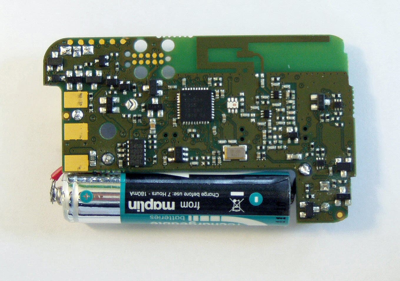
E86EKOFOB
Apr 10, 20132 way alarm and alerting device
Equipment Class
DTS - Digital Transmission System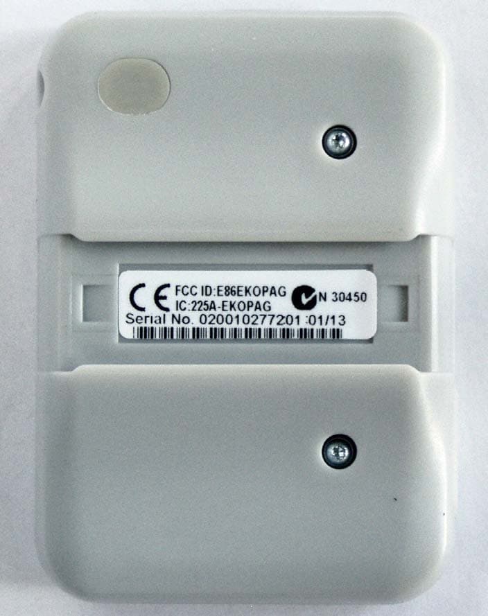
E86EKOPAG
Apr 02, 2013Alpha-numeric 2 way alarm and paging device
Equipment Class
DTS - Digital Transmission SystemE86RPT503
Aug 07, 2008UHF Paging Transmitter
Equipment Class
TNB - Licensed Non-Broadcast Station Transmitter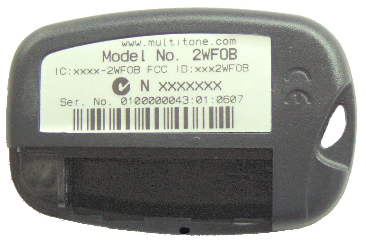
E862WCF
Nov 04, 2007EkoTek FOB - 2 way alerting device
Equipment Class
DTS - Digital Transmission System