E862WHUBEkoTek HUB - Alpha-numeric 2 way messaging device
Multitone Electronics PLC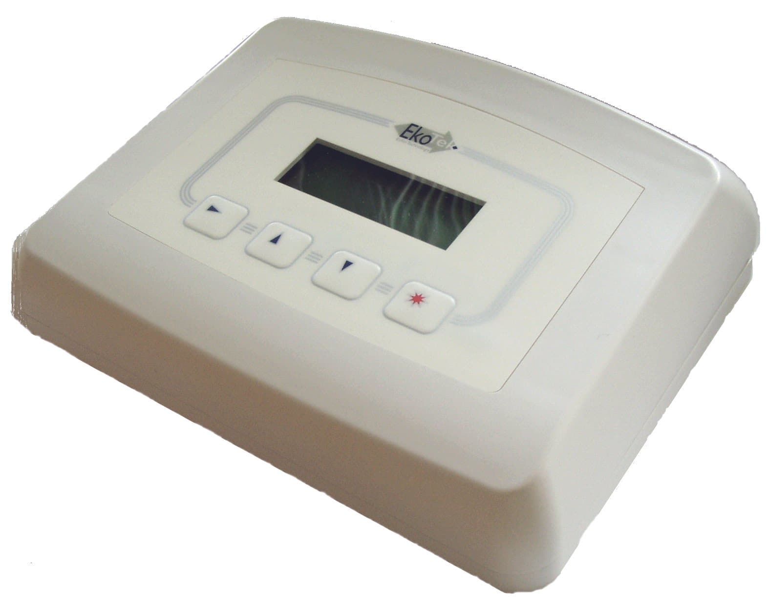
Click to zoom
Application Details
- Equipment Class
- DTS - Digital Transmission System
- Date of Grant
- Nov 04, 2007
- Application Purpose
- Original Equipment
- Date of Application
- Sep 02, 2007
- Equipment Note
- EkoTek HUB - Alpha-numeric 2 way messaging device
- Frequency Range
- 2405.00000000 - 2480.00000000
- Company
- Multitone Electronics PLC
- Country
- United Kingdom
Documents & Files
Document Text
Text extracted from the exhibit documents filed with the FCC. Open a document above to read the original.
Users Manual
EkoTek Hub USER GUIDE For EkoTek Hub 9261- 8276 (Issue 2.0) EkoTek Hub 2 EkoTek Hub CONTENTS Introduction 5 Compliance 6 General User Information 7 EkoTek System Schematic 8 Powering Up the EkoTek Hub 9 Status and Warning Messages 10 Using the Emergency / Assist Button 11 Dead Man Alert 12 Receiving a Message 13 Reading a Message 15 Viewing a Message Again 16 Accepting, Rejecting & Deleting Two-Way Messages 17 Deleting a Message 18 Delete All Messages 20 Archiving a Message 21 Reviewing Archived Messages 22 Deleting Archived Messages 23 Delete All Archived Messages 24 Set Time and Date 25 Part No. 9261-8276 Issue 1.0 3 EkoTek Hub Set 12/24 Hour Mode 26 Set Day / Night Mode 27 Setting the Alert Options 28 Setting the Message Display Options 29 Setting Auto Delete 31 IP Address 32 Part No. 9261-8276 Issue 1.0 4 EkoTek Hub Introduction The EkoTek Hub is an alphanumeric two-way messaging device, incorporating an emergency calling/assist facility. The EkoTek Hub is able to receive text messages, allows basic responses and provides the ability to store messages for later viewing. The high contrast screen is capable of displaying up to 150 characters and all menus are displayed in plain language text. Operation of all functions is performed via intuitive menus using 4 tactile buttons and the Red Star button is used for assist or emergency applications. To gain full benefit from this product please read this guide carefully. Function / Control Buttons X S T Ä Select / Enter Button Scroll Up Button Scroll Down Button Emergency / Assist Button Select & Enter Button Denoted by the X symbol, this button is used to move to and confirm selected options within the Menu Screens and to return to the Standby Screen when pressed for more than 1 second. Scroll Up/Down Buttons Denoted by the S (Up) and T (Down) Symbols. These buttons are used to scroll up and down the Menu Screens. Emergency & Assist Button Denoted by the Red Star button, this can be either Single or Double press. Operation is dependent upon product configuration. Part No. 9261-8276 Issue 1.0 5 EkoTek Hub Compliance This product complies with the requirements of the EU Radio & Telecommunications Terminal Equipment Directive 99/5/EC. FCC & Industry Canada Statement Of Compliance This device complies with Part 15 of the FCC Rules and Industry Canada Standard RSS 210. Operation is subject to the following two conditions: (1) this device may not cause harmful interference and (2) this device must accept any interference that may cause undesired operation. Unauthorised modification to this equipment will void the user's authority to continue to operate the device within the scope of the Industry Canada and FCC Part 15 Rules. A full technical specification for this product may be obtained from your Multitone representative. WEEE Directive & Product Disposal At the end of its serviceable life, this product should not be treated as household, or general waste. It should be handed over to the applicable collection point for the recycling of electrical and electronic equipment, or returned to the supplier for disposal. Part No. 9261-8276 Issue 1.0 6 EkoTek Hub General User Information Radio Reception The EkoTek Hub has been designed to give optimum performance within the coverage area of the wireless network. Hazardous Areas The EkoTek Hub must not be installed in areas where explosive gas, or dust products, may be present. EkoTek Hub Care Protect the EkoTek Hub from liquids, extreme temperatures and strong magnetic fields. Do not install in a place where it will be exposed to strong sunlight. Servicing Should the EkoTeK Hub need repair, return it to the designated service agent. Do not attempt to open or repair the product, as it contains delicate components and requires specialised test equipment. Part No. 9261-8276 Issue 1.0 7 EkoTek Hub EkoTek System Schematic EkoTek Self Organising & Repairing Wireless Mesh Network Power Adaptor AC Repeater Wireless Call Fob Pager Repeater Repeater Repeater Battery Powered Repeater to Repeater Distance T ypically 10 to 15m Includes Personal Security Alarm Hub With Web Server Part No. 9261-8276 Issue 1.0 8 EkoTek Hub Powering Up the EkoTek Hub The EkoTek Hub is powered via a 110, 220 or 240 Volt switch mode power supply unit. On switching on the EkoTek Hub a message will then be displayed for three seconds, whilst self-checks are being performed. Finally, the Standby Screen will be displayed: 12!00 AM 01.01.06 Day No Unread Messages An exclamation mark (!) will flash between the Hours and the Minutes (11!34 AM). This indicates that the EkoTek Hub is in the process of starting up. Once the EkoTek Hub has started up this will change to a ‘period’ symbol and the EkoTek Hub will automatically synchronise with the EkoTek network. The 4 th line of the screen will display ‘EkoTek’ once the EkoTek Hub has initialised: 11:34 AM 12.03.07 Day No Unread Messages EkoTek Part No. 9261-8276 Issue 1.0 9 EkoTek Hub Status and Warning Messages When the EkoTek Hub is switched on the Standby Screen is displayed. This consists of the time and date plus additional status and warning messages. A typical screen is shown below: 11:34 AM 12.03.07 Day 1 Unread Message Silent EkoTeK The first line is the clock displaying the current time and date, the time may be in either a 12 or 24-hour format. In the top right hand corner the hub will display Day or Night this is used to indicate the shift mode. The second line displays No Unread Messages or ‘n’ Unread Message, showing how many messages have been received but not viewed. The third line shows the status of the alert, Silent to warn that the audible alert has been turned off. If nothing is displayed then the audible alert is turned on The fourth line normally displays the EkoTek logo, however, if the AC power is removed and the hub is running on its internal back-up batteries, Mains Fail is displayed. Part No. 9261-8276 Issue 1.0 10 EkoTek Hub Using the Emergency / Assist Button Note: This …
Text truncated - open the document above for the full version.
Cover Letter(s)
1 Multitone Electronics plc Multitone House, Shortwood Copse Lane, Kempshott, Basingstoke, Hampshire, RG23 7NL Tel: +44 (0)1256 320292 Fax: +44 (0)1256 462643 Website: www.multitone.com Federal Communications Commission, 7435 Oakland Mills Road, Columbia, MD 21046 USA 3rd September 2007 Certification Of Product to FCC R & R's, Part 15 Subpart C Multitone EkoTek Series HUB - E862WHUB Dear Sirs, We wish to make application for the Certification of the above referenced equipment as part of our EkoTek Series of products, under the auspices of R & R Part 15, Subpart C, Section 15.247. Further separate Form 731's have been completed and supporting exhibits attached, for each individual equipment that further form this Series. Based around the IEEE 802.15.4 standard for Low Rate Wireless Personal Area Networks (WPANs) and the proprietary TI chipset CC2430, the EkoTek Series of equipments form an intelligent personal security/lone-worker alarm system, which operates over a 2.4GHz, low power RF self-organising radio network. The system allows assistance calls, general and/or emergency; to be made via the radio network, with both location display and response call facilities. Digital modulation and frequency-hopping techniques are used to enable the simultaneous carriage of traffic volume and to avoid interference from nearby equipments, also operating in the 2.4GHz ISM band e.g. WiFi. The system comprises 4 basic equipments, 2 portable and 2 fixed, for each of which separate applications will be made. The device that is the subject of this application is the: - HUB (2WHUB) - central device to the mesh network; all communication passes to and from the HUB, which can be located at any point within the network. The HUB displays alarm calls; may be configured and monitored from a PC via an Ethernet link and has external Serial ports for other alarm and paging system connections. Other devices on the system include the: - Call FOB (2WCF) - portable device worn/carried by personnel; 2-Way Pager (2WPAG) - provides the same alarm generation facilities as the FOB, but also has the added benefit of an alphanumeric display and the Repeater (Node)/Call-point repeater (2WREP). Further details of these equipments, may be found under their own applications. SDR - This equipment may be classed as a Software-Defined Radio. It may be further broadly classified as a Master device. The HUB continuously transmits a Main Beacon every second, which provides system information such as time/date, quality of link to HUB, any messages (both outgoing and acknowledgement of incoming) and frequency-hopping information. Additionally, it also transmits a second localised location beacon signal every second, at a lower RF power (-14dB relative to Main Beacon nominal). Multitone Electronics plc is part of Kantone Holdings Ltd., a member of the Champion Technology group of companies. Registered in England Number 256314 Registered Address, Multitone House, Shortwood Copse Lane, Basingstoke, Hampshire, RG23 7NL 2 However, it is intended that the control of the software that is used to define the radio parameters, be retained within Multitone. Each unit will be pre-programmed before dispatch and the only radio parameter which may be changed during installation, is the default RF channel within the band, which is used by the HUB and possibly by the repeaters (see System Installation & Configuration Manual). Software Control - The software which controls the RF parameters for all the EkoTek products is Multitone proprietary and is controlled by the company development group and company QA procedure P020/02, which forms part of our ISO 9001certification. As stated above, each equipment is pre-programmed before dispatch and at this time no other external access is to be allowed to the RF parameter software, apart from setting the default RF channel during network installation. The only accessible software control is for network parameter setting. Servicing - It is not intended that the EkoTek products be field serviceable. They will be either returned to Multitone or our agents for repair and/or replaced with another unit. RF Exposure - The nominal RF ERP of the device, is 10mW. This falls below the lower threshold category for General Population exposure (for f 2.4GHz, 25mW) for d <2.5cm. The product is intended to be desk-top or wall mounted. Confidentiality - We wish to request Permanent Confidentiality for parts of this item under the terms of R & R 0.457 and as denoted on the Form 731, please see separate request letter. Documentation - In addition to the product specific documentation, I have also attached the generic data sheets and overall system documents to this application. These items will also be relevant to the other related EkoTek submissions. I hope that the information supplied enables you to make an initial assessment of the equipment. Once you have formed further questions, please do not hesitate to contact me. E-mail is probably the most efficient route. Yours sincerely, B.R.Merchant Principal Approvals Engineer Multitone Electronics plc Multitone Electronics plc is part of Kantone Holdings Ltd., a member of the Champion Technology group of companies. Registered in England Number 256314 Registered Address, Multitone House, Shortwood Copse Lane, Basingstoke, Hampshire, RG23 7NL 3 Multitone Electronics plc Multitone House, Shortwood Copse Lane, Kempshott, Basingstoke, Hampshire, RG23 7NL Tel: +44 (0)1256 320292 Fax: +44 (0)1256 462643 Website: www.multitone.com Federal Communications Commission, 7435 Oakland Mills Road, Columbia, MD 21046 USA 3rd September 2007 Request For Confidentiality Multitone EkoTek Series HUB - E862WHUB Dear Sirs, In accordance with Rule Parts 0.457 & 0.459, we hereby request that the following exhibits entered as part of the certification process for the above product, be held as Permanently Confidential. Schematics:- 2961-8059-2; 0261-8060-2; 3061-8061-2 2961-8150-1; 0261-8151-1; 3061-8152-1. T…
Text truncated - open the document above for the full version.
External Photos
EkoTek HUB - General External View
ID Label/Location Info
EkoTek HUB - Label& Label Area
ID Label/Location Info
EkoTek HUB - Label& Label Area (2)
Internal Photos
EkoTek HUB - General Internal Assembly EkoTek HUB - General Internal View EkoTek HUB - Main PCB Top EkoTek HUB - Main PCB Underside
Operational Description
EkoTek Low Power Radio Mesh Networking Table of Contents 1Scope3 2Background3 3Requirements4 4Radio Technology4 5Meeting the Requirements4 5.1 Battery power : IEEE 802.15.44 - 5 5.2 Resilience5 5.3 Self-Configuration6 5.4 Ease of Expansion6 - 7 6Summary7 2 1/Scope This document gives an overview of a radio mesh network and the low power technology that can be used for implementation of the network. 2/Background A mesh network is a type of network where co-operating nodes form connections that are used for traffic flow through the network. The term “mesh” is used as traffic may have more than one potential route through the network, providing the possibility of traffic load sharing and resilience. The Internet is a well known mesh network, where Internet Routers form the network nodes that handle the traffic flow. This document is specifically concerned with low power radio mesh networking and describes an implementation used by Multitone Electronics in its EkoTek range of products. 3 Rep Rep Rep Pager Call Point Call Point Pager Call Point Pager Hub Rep 3/Requirements Key requirements for a low power radio mesh network are : Battery powered with long battery life : as multiple nodes form the mesh network, installation costs would be high if each node required a mains power supply. Battery powering allows nodes to be installed quickly and easily with a very low installation cost. Resilience : failure of any node should not cause the network to fail. The network should automatically route around a failed node. Self-configuration : the number of potential radio paths available in a radio mesh network can be considerable. This makes the network robust but means that manual configuration is not practical. The network must automatically configure routes through the network. Ease of expansion : changes to the network must be straightforward to implement 4/Radio Technology A number of radio technologies exist that could be used to create mesh network- ing products. For Multitone’s EkoTek range of products, the requirement for bat- tery powering with a battery life of at least 2 years meant that the latest technol- ogy low power radio devices were the appropriate solution. The chosen radio technology is IEEE 802.15.4 which specifies a radio technique specifically aimed at battery operated devices and giving a long battery life. 5/Meeting the Requirements 5.1/Battery power : IEEE 802.15.4 This specification defines a radio system that may be used in various ways. In order to minimise power consumption, the ON time of the radio transmitter and receiver must be minimised. This is achieved by operating the node radio in beacon mode. 4 Rep-TXRep-RX 20msec 1000msec Repeater window In beacon mode each node (Repeater) has a specific time window in which it transmits/receives. Outside of this window the node is inactive and therefore battery consumption is minimised. In the above example the node window lasts for 20 msec and repeats every 1000msec. As the window is of relatively short duration, the tx/rx data rate must be relatively high to ensure that sufficient data can flow during the window period :in the case of IEEE 802.15.4 it is 250 kbit/s. 5.2/Resilience Traffic links to neighbouring nodes are continuously tested. Should a link fail, that link is dropped and the node automatically looks for a new link to another node. 5 Node Node Node Node Node Node Node Node Node Node Node Node Node Node Node Node Node Node Node Node Node Node Node Node Node Node Node FAIL Re-route Re-route 5.3/Self-Configuration When a node resets or on failure of a link to an adjacent node, the node performs a radio scan and selects an adjacent node with good signal strength as a route to pass traffic via the network. In the above example, the node that has reset has performed a scan and detected three neighbouring nodes that could potentially be used for traffic links. One of these will be selected, normally based on link testing and signal strength. 5.4/Ease of Expansion Changes to the network, normally expansion but may also involve moving part of the network, must be straightforward to implement. Traditional 1-hop radio networks suffer from the single hop radio path normally requiring multiple wired base stations to provide site coverage, making expansion costly and difficult. A mesh network is easily expanded simply by adding additional nodes (Repeaters) in the required location. In addition, as EkoTek’s Repeaters are battery powered, no wires are required to be installed for expansion, making the task very quick and easy. 6 Node Node Node Node Node Node Potential links Node reset 6/Summary The IEEE 802.15.4 radio network chosen for Multitone’s EkoTek range of products provides the following : Ease and low cost of installation due to the use of battery powered nodes (Repeaters). Long battery life using beacon window tx/rx. Ease of installation as the network self-configures at startup. Resilience as the network automatically re-configures on node or link failure. Easy expansion simply by adding battery powered nodes (Repeaters) where required. 7 EkoTek Personal Security & Lone Worker System Overview Table of Contents 1Scope of Document3 2EkoTek Personal Security / Lone Worker System3 - 4 3Applications4 3.1 Building Security4 3.2 Hospital Security4 3.3 Nurse Call4 3.4 Security Guard Protection4 - 5 3.5 Car Park and Campus Security5 3.6 Co-worker Calling5 3.7 2-Way Task Management5 4EkoTek Principles5 4.1 Self-Organising Mesh Radio6-7 4.2 Accurate Location Reporting8 4.2.1 2-Way Acknowledgement8 4.3 2-Way Radio8 - 9 4.3.1 Frequency Hopping9 5Components9 5.1 Single Hub9 - 10 5.2 Call Fob10 5.3 Repeater10 - 11 5.4 Call Point / Repeater11 5.5 2-Way Pager12 5.5.1 Display of and Response to Assistance Calls12 5.5.2 Display of Webserver Paging Messages12 5.5.3 Paging from External System13 5.5.4 Personal Security Calls13 5.5.5 Powering13 5.6 Configuration13 5.6.1 Network Parameters13 - 14 6Diagnostics and Statistics14 7Specificat…
Text truncated - open the document above for the full version.
RF Exposure Info
Multitone Electronics plc Multitone House, Shortwood Copse Lane, Kempshott, Basingstoke, Hampshire, RG23 7NL Tel: +44 (0)1256 320292 Fax: +44 (0)1256 462643 Website: www.multitone.com Federal Communications Commission, 7435 Oakland Mills Road, Columbia, MD 21046 USA Maximum Permitted Exposure (MPE) Compliance Statement For Multitone EkoTek Series HUB - FCC ID: E862WHUB The Multitone EkoTek 2WHUB 2-way Radio Paging & Data equipment (2.405 - 2.48GHz) , contains a low power (10mW) RF transmitter and is intended for fixed use with the integral unity gain (or less) antenna supplied. The equipment's performance may be characterized in accordance with the exposure requirements of 47 CFR 1.1307, as below. At the mid-band frequency of the equipment's spectrum of operation, the RF output power level of the equipment falls below the FCC's General Population Uncontrolled Exposure Limits, as specified in document OET 65. Derivative analysis of this result is as follows: - For the general uncontrolled population, the Maximum Permissible Exposure (MPE) power density limit is 1mW/cm 2 . The prediction method provided for the distance at which this level occurs, is based the following worst-case (far-field) calculation: - Power Density (P D ) = EIRP/(4BR 2 ) Using this formula for the 2WHUB with the following values inserted; P D = 1mW/cm 2 ; EIRP = 10mW, yields a radius figure of 0.9cm from the antenna. In normal use the user is prevented from approaching the antenna to such a point, by the case construction of the equipment and where close operation of the unit is required, this is limited in time to periods well below the specified Averaging Time. Dated this 29th Day Of October 2007 Signed: B.R.Merchant, Principal Approvals Engineer, Multitone Electronics plc Telephone: - +44 1256 320292 e-mail: - [email protected] Multitone Electronics plc is part of Kantone Holdings Ltd., a member of the Champion Technology group of companies. Registered in England Number 256314 Registered Address, Multitone House, Shortwood Copse Lane, Basingstoke, Hampshire, RG23 7NL
Schematics
CC2430 CC2430 Data Sheet (rev. 2.1) SWRS036F Page 1 of 211 A True System-on-Chip solution for 2.4 GHz IEEE 802.15.4 / ZigBee ® Applications • 2.4 GHz IEEE 802.15.4 systems • ZigBee ® systems • Home/building automation • Industrial Control and Monitoring • Low power wireless sensor networks • PC peripherals • Set-top boxes and remote controls • Consumer Electronics Product Description The CC2430 comes in three different flash versions: CC2430F32/64/128, with 32/64/128 KB of flash memory respectively. The CC2430 is a true System-on-Chip (SoC) solution specifically tailored for IEEE 802.15.4 and ZigBee ® applications. It enables ZigBee ® nodes to be built with very low total bill-of- material costs. The CC2430 combines the excellent performance of the leading CC2420 RF transceiver with an industry-standard enhanced 8051 MCU, 32/64/128 KB flash memory, 8 KB RAM and many other powerful features. Combined with the industry leading ZigBee ® protocol stack (Z-Stack™) from Texas Instruments, the CC2430 provides the market’s most competitive ZigBee ® solution. The CC2430 is highly suited for systems where ultra low power consumption is required. This is ensured by various operating modes. Short transition times between operating modes further ensure low power consumption. Key Features • RF/Layout o 2.4 GHz IEEE 802.15.4 compliant RF transceiver (industry leading CC2420 radio core) o Excellent receiver sensitivity and robustness to interferers o Very few external components o Only a single crystal needed for mesh network systems o RoHS compliant 7x7mm QLP48 package • Low Power o Low current consumption (RX: 27 mA, TX: 27 mA, microcontroller running at 32 MHz) o Only 0.5 μA current consumption in powerdown mode, where external interrupts or the RTC can wake up the system o 0.3 μA current consumption in stand-by mode, where external interrupts can wake up the system o Very fast transition times from low-power modes to active mode enables ultra low average power consumption in low dutycycle systems o Wide supply voltage range (2.0V - 3.6V) • Microcontroller o High performance and low power 8051 microcontroller core o 32, 64 or 128 KB in-system programmable flash o 8 KB RAM, 4 KB with data retention in all power modes o Powerful DMA functionality o Watchdog timer o One IEEE 802.15.4 MAC timer, one general 16-bit timer and two 8-bit timers o Hardware debug support • Peripherals o CSMA/CA hardware support. o Digital RSSI / LQI support o Battery monitor and temperature sensor o 12-bit ADC with up to eight inputs and configurable resolution o AES security coprocessor o Two powerful USARTs with support for several serial protocols o 21 general I/O pins, two with 20mA sink/source capability • Development tools o Powerful and flexible development tools available CC2430 CC2430 Data Sheet (rev. 2.1) SWRS036F Page 2 of 211 Table Of Contents 1 ABBREVIATIONS ................................................................................................................................ 5 2 REFERENCES....................................................................................................................................... 7 3 REGISTER CONVENTIONS .............................................................................................................. 8 4 FEATURES EMPHASIZED ................................................................................................................ 9 4.1 HIGH-PERFORMANCE AND LOW-POWER 8051-COMPATIBLE MICROCONTROLLER............................... 9 4.2 UP TO 128 KB NON-VOLATILE PROGRAM MEMORY AND 2 X 4 KB DATA MEMORY............................ 9 4.3 HARDWARE AES ENCRYPTION/DECRYPTION....................................................................................... 9 4.4 PERIPHERAL FEATURES......................................................................................................................... 9 4.5 LOW POWER.......................................................................................................................................... 9 4.6 IEEE 802.15.4 MAC HARDWARE SUPPORT........................................................................................... 9 4.7 INTEGRATED 2.4GHZ DSSS DIGITAL RADIO........................................................................................ 9 5 ABSOLUTE MAXIMUM RATINGS ................................................................................................ 10 6 OPERATING CONDITIONS............................................................................................................. 10 7 ELECTRICAL SPECIFICATIONS .................................................................................................. 11 7.1 GENERAL CHARACTERISTICS.............................................................................................................. 12 7.2 RF RECEIVE SECTION......................................................................................................................... 13 7.3 RF TRANSMIT SECTION....................................................................................................................... 13 7.4 32 MHZ CRYSTAL OSCILLATOR.......................................................................................................... 14 7.5 32.768 KHZ CRYSTAL OSCILLATOR.................................................................................................... 14 7.6 32 KHZ RC OSCILLATOR..................................................................................................................... 15 7.7 16 MHZ RC OSCILLATOR................................................................................................................... 15 7.8 FREQUENCY SYNTHESIZER CHARACTERISTICS................................................................................... 16 7.9 ANALOG TEMPERATURE SENSOR........................................................................................................ 16 7.10 ADC ......…
Text truncated - open the document above for the full version.
Test Report
TEST REPORT FROM RFI GLOBAL SERVICES LTD Test of: Multitone Electronics Plc EkoTek - Hub To: FCC Part 15.247: 2006 (Subpart C) Test Report Serial No: RFI/RPTE2/RP48909JD09A Supersedes Test Report Serial No: RFI/RPTE1/RP48909JD09A This Test Report Is Issued Under The Authority Of Michael Derby, Radio Performance Service Leader: Tested By: Nirav Modi Checked By: Michael Derby Report Copy No: PDF01 Issue Date: 12 July 2007 Test Dates: 04 June 2007 to 21 June 2007 This report is issued in Adobe Acrobat portable document format (PDF). It is only a valid copy of the report if it is being viewed in PDF format with the following security options not allowed: Changing the document, Selecting text and graphics, Adding or changing notes and form fields. This report may be copied in full. The results in this report apply only to the sample(s) tested. RFI GLOBAL SERVICES LTD TEST REPORT S.No. RFI/RPTE2/RP48909JD09A Page: 2 of 50 Issue Date: 12 July 2007 Test of: Multitone Electronics Plc EkoTek - Hub To: FCC Part 15.247: 2006 (Subpart C) This page has been left intentionally blank. RFI GLOBAL SERVICES LTD TEST REPORT S.No. RFI/RPTE2/RP48909JD09A Page: 3 of 50 Issue Date: 12 July 2007 Test of: Multitone Electronics Plc EkoTek - Hub To: FCC Part 15.247: 2006 (Subpart C) Table of Contents 1. Client Information............................................................................................................. 4 2. Equipment Under Test (EUT) .......................................................................................... 5 3. Test Results ...................................................................................................................... 7 4. Deviations from the Test Specification .......................................................................... 7 5. Operation of the EUT during Testing ............................................................................. 8 6. Summary of Test Results ................................................................................................ 9 7. Measurements, Examinations and Derived Results ................................................... 10 8. Measurement Uncertainty ............................................................................................. 38 9. Measurement Methods .................................................................................................. 39 Appendix 1. Test Equipment Used ................................................................................... 45 Appendix 2. Test Configuration Drawings ....................................................................... 48 RFI GLOBAL SERVICES LTD TEST REPORT S.No. RFI/RPTE2/RP48909JD09A Page: 4 of 50 Issue Date: 12 July 2007 Test of: Multitone Electronics Plc EkoTek - Hub To: FCC Part 15.247: 2006 (Subpart C) 1. Client Information Company Name: Multitone Electronics Plc Address: Multitone House Shortwood Copse Lane Kempshott Basingstoke Hampshire RG23 7NL UK Contact Name: Mr B Merchant RFI GLOBAL SERVICES LTD TEST REPORT S.No. RFI/RPTE2/RP48909JD09A Page: 5 of 50 Issue Date: 12 July 2007 Test of: Multitone Electronics Plc EkoTek - Hub To: FCC Part 15.247: 2006 (Subpart C) 2. Equipment Under Test (EUT) The following information (with the exception of the Date of Receipt) has been supplied by the client: 2.1. Identification of Equipment Under Test (EUT) Description: Radio Network Central Device Brand Name: Multitone Model Name or Number: EkoTek - HUB Unique Type Identification: 2WHUB Serial Number: 66 Hardware Version: C Software Version: Issue 1 – modified for test coverage FCC ID Number: E862WHUB Country of Manufacture: Malacca Date of Receipt: 04 …
Text truncated - open the document above for the full version.
Contact Information
Applicant
B. R. Merchant(Principal Approvals Engineer)
Technical Contact
Multitone Electronics plcBrian Ronald Merchant
[email protected]+441256845148
Multitone House · Basingstoke · United Kingdom
Non-Technical Contact
Multitone Electronics plcBrian Ronald Merchant
[email protected]+441256845148
Test Firm
UL VS LtdDarren Rust
Technical Specifications
| # | Rule Parts | Frequency Range | Power Output |
|---|---|---|---|
| 1 | 15C | 2.40 GHz - 2.48 GHz | 10.00 mW |
Other Applications from Multitone Electronics PLC
E86EKOCPLVRM
Feb 26, 2026EKOTek call point
Equipment Class
DTS - Digital Transmission System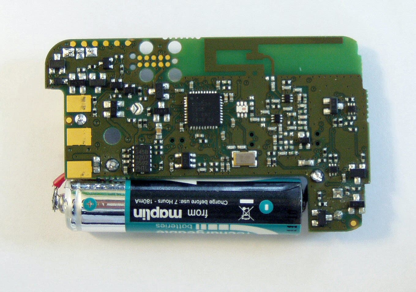
E86EKOFOB
Apr 10, 20132 way alarm and alerting device
Equipment Class
DTS - Digital Transmission System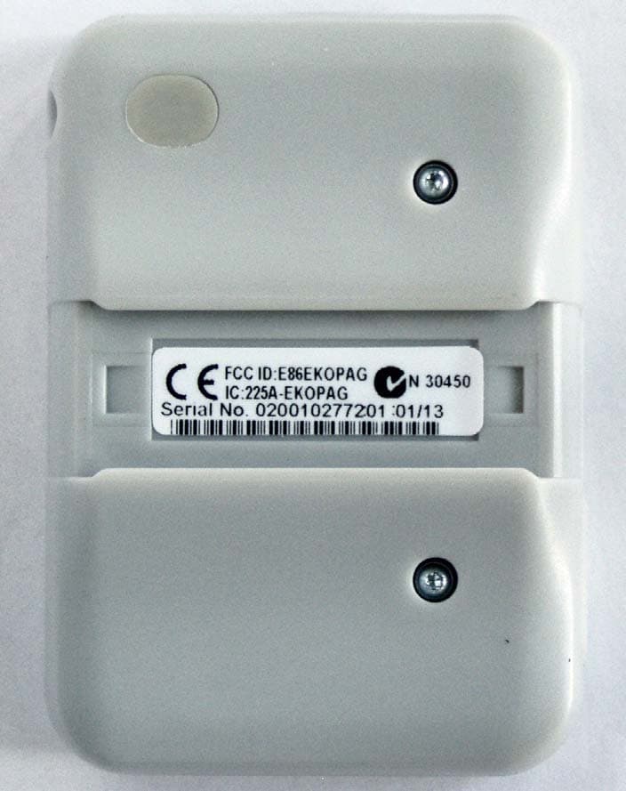
E86EKOPAG
Apr 02, 2013Alpha-numeric 2 way alarm and paging device
Equipment Class
DTS - Digital Transmission System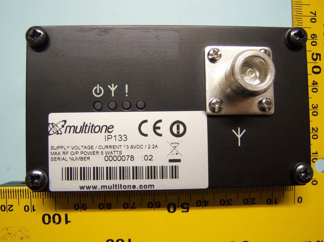
E86IP133
Feb 07, 2012Multitone I-Page � IP133
Equipment Class
TNB - Licensed Non-Broadcast Station TransmitterE86RPT503
Aug 07, 2008UHF Paging Transmitter
Equipment Class
TNB - Licensed Non-Broadcast Station Transmitter