E86TLA-FLAAlphanumeric VHF Radio Paging Receiver
Multitone Electronics PLC
Click to zoom
Application Details
- Equipment Class
- CXX - Communications Rcvr for use w/ licensed Tx and CBs
- Date of Grant
- Dec 18, 2002
- Application Purpose
- Original Equipment
- Date of Application
- Dec 18, 2002
- Equipment Note
- Alphanumeric VHF Radio Paging Receiver
- Frequency Range
- 138.00000000 - 174.10000000
- Company
- Multitone Electronics PLC
- Country
- United Kingdom
Documents & Files
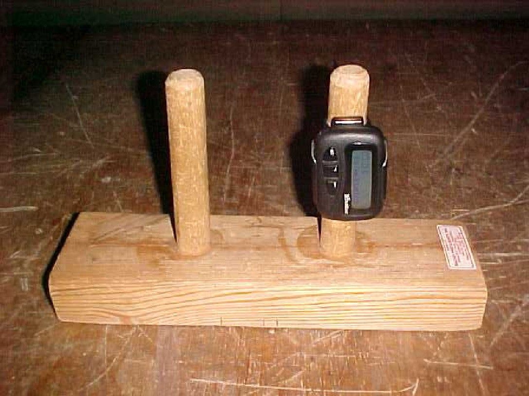
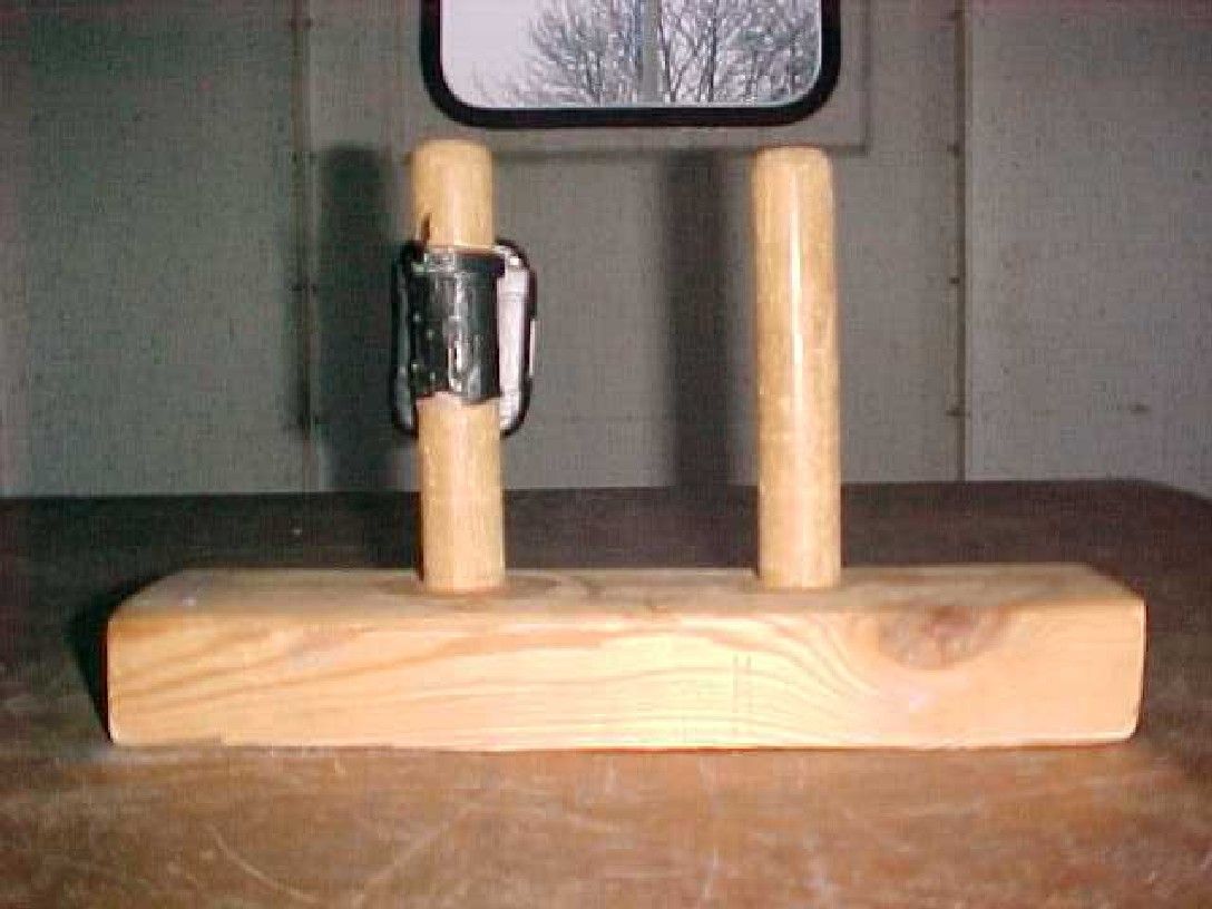
Document Text
Text extracted from the exhibit documents filed with the FCC. Open a document above to read the original.
Users Manual
> TM1205 Issue 1Page (i) TECHNICAL MANUAL for RADIO PAGING RECEIVERS MODEL TLA 852 and MODEL FLA 872 Printed and Published in England TLA 852/FLA 872 TM1205 Issue 2Page (ii) COMPANY LIABILITY The information in this manual has been carefully compiled and checked for technical accuracy. Multitone Electronics plc accept no liability for inaccuracies or errors. In line with the company policy of technical advancement, the information within this document may be changed. The user should ensure that the correct issue of the document is used. Comments or correspondence regarding this manual should be addressed to: Multitone Electronics plc Multitone House Beggarwood Lane Kempshott Hill Basingstoke Hampshire RG23 7LL England ISSUEDATE 2 November 2002 © 2002 Multitone Electronics plc TM1205 Issue 2 Page (iii) CONTENTS Page (i)Title Page Page (ii)Company Liability Page (iii)Contents Page (iv)Effective Page List Page (v)Safety Summary Warning Page (vi)Caution Section 1Introduction and Specification Section 2Operating Instructions Section 3Technical Description Section 4Installation & Commissioning Section 5Servicing Section 6Spare Parts List Section 7Diagrams TLA 852/FLA 872 TM1205 Issue 2Page (iv) EFFECTIVE PAGE LIST Page No.IssuePage No.IssuePage No.Issue (i)12-915-31 (ii)12-1015-41 (iii)12-1115-51 (iv)12-1215-61 (v)12-1315-71 (vi)12-1415-81 1-112-1515-91 1-212-1615-101 1-313-115-111 1-413-215-121 1-513-315-131 1-613-415-141 2-113-515-151 2-213-615-161 2-313-715-171 2-413-815-181 2-513-915-191 2-613-1015-201 2-714-11 2-814-21 5-11 5-21 5-211 5-221 5-231 5-241 Page No.Issue 5-251 5-261 6-11 6-21 6-31 6-41 6-51 6-61 6-71 6-81 7-11 7-21 7-3/41 7-5/61 7-7/81 7-9/101 7-11/121 7-13/141 7-15/161 7-17/18 1 7-19/201 7-21/221 TM1205 Issue 1Page (v) THE RECEIVER SHOULD NOT BE CARRIED INTO AREAS WHERE EXPLOSIVE GASES, OR DUST MAY BE PRESENT. FCC & IC Statement Of Compliance This device complies with FCC Part 15 & Industry Canada RSS210 regulations. Operation is subject to the following two conditions:- (1) this device may not cause harmful interference and (2) this device must accept any interference received, including interference that may cause undesired operation. Unauthorised modification to this equipment, will void the user’s authority to operate the device under the terms of the above regulations. SAFETY SUMMARY The following information applies to both operating and servicing personnel. General Warnings and Cautions will be found throughout the manual, where they apply, which refer to the applicable part of this summary. WARNING statements identify conditions or practices that could result in personal injury or loss of life. CAUTION statements identify conditions or practices that could result in equipment damage. WARNING CAUTION STATIC SENSITIVE DEVICES ARE USED WITHIN THIS EQUIPMENT. CARE MUST BE USED TO ENSURE DAMAGE TO THESE DEVICES IS NOT CAUSED BY HIGH LEVELS OF STATIC ELECTRICITY. SPARE BOARDS OR COMPONENTS SHOULD BE STORED IN ANTI-STATIC PACKAGING WHEN NOT INSTALLED IN THE EQUIPMENT. PROTECT THE RECEIVER FROM LIQUIDS, STRONG MAGNETIC FIELDS AND EXTREME TEMPERATURES. DO NOT LEAVE THE RECEIVER EXPOSED TO STRONG SUNLIGHT. AREAS SUCH AS WINDOW LEDGES ARE TO BE AVOIDED. TLA 852/FLA 872 TM1205 Issue 2Page (vi) INTENTIONALLY BLANK TLA 852/FLA 872 TM1205 Issue 2 Page 1 - 1 SECTION 1 INTRODUCTION & SPECIFICATION CONTENTS:Page 1.1INTRODUCTION1 - 2 1.2FEATURES1 - 3 1.3SPECIFICATIONS1 - 3 1.3.1Receiver Performance1 - 3 1.3.2Power Supply1 - 4 1.3.3Code Format1 - 4 1.3.4Memory1 - 5 1.3.5Displays, Controls and Alerts1 - 5 1.3.6Operational Environment1 - 6 1.3.7Physical Characteristics1 - 6 TABLES: 1.1Sensitivity Figures1 - 4 TLA 852/FLA 872 TM1205 Issue 2Page 1 - 2 1.1INTRODUCTION The MultitoneTLA 852 and FLA 872 Radio Paging Receivers are VHF receivers which receive messages sent in CCIR Radiopaging Code No.1 (RPC1). The front panel of the unit has a Liquid Crystal Display (LCD) to display messages and other information. The three buttons on the front panel are used to control the functions of the unit. The LCD of the TLA 852 can show a maximum of two lines of 20 alphanumeric characters; the FLA 872 has the option of showing a maximum of four lines of 20 characters, or two lines of double height characters. The displays can also show a maximum of seven symbols in a line. If the TLA 852 receives a message that is longer than 40 characters, it displays the first 40 and stores the excess. The front panel buttons are used to transfer the stored part of the message to the screen as required. Similarly, if the FLA 872 receives a message which has more than 80 characters (40 characters in double height mode) the excess characters are stored. Message alert is provided by an audible beep tone or by the unit vibrating. The buttons are used to select the preferred alert. Power for the unit is supplied by a single AAA battery. A door on the rear of the unit gives access to the battery. A back-up supply for the unit is available when the battery is changed. The back-up supply is provided by a large-value capacitor mounted on the decoder board in the unit. The capacitor, when fully charged, can maintain data in the unit for more than 5 minutes. The unit case is a two-piece plastic moulding secured by two cross-head screws. A lanyard is supplied with the unit which can be fastened to the case and the attached clip used to secure the unit to a suitable object. TLA 852/FLA 872 TM1205 Issue 2 Page 1 - 3 1.2FEATURES The unit has these features: !Displays two lines of 20 characters - TLA 852 (four lines - FLA 872) !Message Store !Information Service Messages (Optional) !Display Backlight !Date/Time Display !Selectable Alert - Audible Beep or Vibration !Alarm !Out of Range Indication (Optional) !Timed-off Mode !Low Battery Warning !Battery Economy 1.3SPECIFICATIONS 1.3.1Receiver Performance Frequency Range:138MHz through 174.1MHz Frequency Bands: Band 1:138.000MHz - 143.499MHz Band 2:143.500MHz - 148.999MHz Band 3:149.000MHz…
Text truncated - open the document above for the full version.
Users Manual
USER GUIDE FOR ALPHANUMERIC RECEIVER FLA 870 AND SECURE PAGING VARIANTS 9261-6366 iss 2 21/11/02 9:04 am Page 1 9261-6366 iss 2 21/11/02 9:04 am Page 2 FCC Statement Of Compliance This device compli es with FCC Part 15 regulations. Operation is subject to the following two conditions:- (1) this device may not cause harmful interference and (2) this device must accept any interference received, including interference that may cause undesired operation. Unauthorised modification to this equipment, will void the user’s authority to operate the device under the terms of the above regulations. Contents Introduction and Getting Started .................. 1 Switching the Pager On ................................ 1 Status and Operating Symbols .................... 2 Setting the Time and Date ............................ 4 Setting the Alarm .......................................... 6 Selecting the Alert ........................................ 8 Selecting Display Options .......................... 10 Receiving a Message ..................................11 Reviewing Stored Messages ...................... 12 Archiving Messages .................................. 13 Reviewing Archived Messages ....................14 Deleting a Message ....................................15 Deleting all Messages ................................15 Reviewing information Service messages .. 17 Secure Messaging Options ........................ 18 Z-Page: Activation and Protection .............. 19 Reading Z-Page Messages ........................ 19 Z-Page: Notes of Caution .......................... 20 (i) 9261-6366 iss 2 21/11/02 9:04 am Page 3 KeyPage Operation .................................... 21 KeyPage Message Access.......................... 22 KeyPage PIN Changes................................ 23 KeyPage PIN Reset .................................... 24 KeyPage Barred Access ............................ 24 Caring for your Pager ................................ 25 Fault-Finding .............................................. 25 (ii) 9261-6366 iss 2 21/11/02 9:04 am Page 4 Introduction and Getting Started Congratulations on selecting the FLA870 alphanumeric pager from Multitone. Your pager has all the features you expect from a top class product yet it retains simplicity of operation through the superbly designed user interface and icon menu selection. This guide will describe the operation of the product and ensure that you receive the full benefits of paging with the FLA870. On the back of your pager you will find the battery cover. Slide the cover in the direction of the arrow to remove. Insert the battery matching the + to + . Carefully slide the cover back into position. Switching the pager ON To turn the pager ON press and hold the • > button for one second. A short alert will sound and the pre programmed Switch On message will be displayed. 1 9261-6366 iss 2 21/11/02 9:04 am Page 5 After one second the time and date will be shown. This is the standby display. Standby Screen Status and Operating Symbols The standby display shows the current time and date. It also shows if there are unread messages, whether audible or vibrate alert is selected and, if appropriate, gives low battery and out of Range warnings by displaying the following symbols: Status Symbols 14 : 2420. 02. 00 14 : 2620. 02. 00 2 9261-6366 iss 2 21/11/02 9:04 am Page 6 The status symbols are as follows: Unread MessagesLow Battery Audible AlertOut-of-Range VibrateMemory Full From the standby display press • > to enter the pager options screen. The following symbols are displayed:- Pager Option Screen Alarm FunctionAlert Selection BacklightOff Time Setting andDelete All Timed Off SetupMessages Pager MenuSecure Pin Optionsentry 3 9261-6366 iss 2 21/11/02 9:04 am Page 7 To turn the pager OFF press • > to show the pager options and then press <or > several times untilis flashing. Press • > and the display will showplus flashing. Press • > again to turn the pager off. Setting the Time and Date The pager standby screen will normally show the time and date. To set the current time and date press • > once to display the pager options and then press <or >several times until theflashes. Press • > twice to display the time function edit screen. Time Function Screen The clock symbol will flash. To set the clock press • > and the clock symbol will appear 4 9261-6366 iss 2 21/11/02 9:04 am Page 8 with 12 or 24 hour mode indicated. The hour will flash and the correct value may be selected by pressing either <or >. Once the hour is correct press • > and the tens of minutes will flash. Press <or >until the correct number is shown and then press • > . Press <or >until the correct number is shown and then press • > to set the minutes. 5 5 : 27pm20. 02. 00 12 5 : 27pm20. 02. 00 12 5 : 27pm20. 02. 00 12 9261-6366 iss 2 21/11/02 9:04 am Page 9 The date is set with the same method. Once the display shows the correct time and date the 12 or 24 hour mode can be selected by pressing the <or >buttons to change as required. Press and hold • > for one second to return the pager to the standby screen. Setting the Pager Alarm The pager has a daily alarm feature and it may be set by pressing the • > to show the pager options and then selectingsymbol using < or >buttons. Press the • > to display the alarm options screen. 6 24 17 : 2720. 02. 00 9261-6366 iss 2 21/11/02 9:04 am Page 10 To turn the alarm on press <or >until symbol shows and the time that the alarm is set to sound is displayed. To turn the alarm off press <or >until symbol shows and the alarm time is turned off. To change the alarm time press • > and the hour will flash. Press <or >to change the numbers and when the correct value is set press • > and the tens of minutes will flash. Press <or >to change the numbers and when the correct value is shown press • > . 7 07 : 00 9261-6366 iss 2 21/11/02 9:04 am Page 11 Press <or >until the minutes display is correct and then press • > for one second to return to the sta…
Text truncated - open the document above for the full version.
Block Diagram
> TM1205 Issue 1Page (i) TECHNICAL MANUAL for RADIO PAGING RECEIVERS MODEL TLA 852 and MODEL FLA 872 Printed and Published in England TLA 852/FLA 872 TM1205 Issue 2Page (ii) COMPANY LIABILITY The information in this manual has been carefully compiled and checked for technical accuracy. Multitone Electronics plc accept no liability for inaccuracies or errors. In line with the company policy of technical advancement, the information within this document may be changed. The user should ensure that the correct issue of the document is used. Comments or correspondence regarding this manual should be addressed to: Multitone Electronics plc Multitone House Beggarwood Lane Kempshott Hill Basingstoke Hampshire RG23 7LL England ISSUEDATE 2 November 2002 © 2002 Multitone Electronics plc TM1205 Issue 2 Page (iii) CONTENTS Page (i)Title Page Page (ii)Company Liability Page (iii)Contents Page (iv)Effective Page List Page (v)Safety Summary Warning Page (vi)Caution Section 1Introduction and Specification Section 2Operating Instructions Section 3Technical Description Section 4Installation & Commissioning Section 5Servicing Section 6Spare Parts List Section 7Diagrams TLA 852/FLA 872 TM1205 Issue 2Page (iv) EFFECTIVE PAGE LIST Page No.IssuePage No.IssuePage No.Issue (i)12-915-31 (ii)12-1015-41 (iii)12-1115-51 (iv)12-1215-61 (v)12-1315-71 (vi)12-1415-81 1-112-1515-91 1-212-1615-101 1-313-115-111 1-413-215-121 1-513-315-131 1-613-415-141 2-113-515-151 2-213-615-161 2-313-715-171 2-413-815-181 2-513-915-191 2-613-1015-201 2-714-11 2-814-21 5-11 5-21 5-211 5-221 5-231 5-241 Page No.Issue 5-251 5-261 6-11 6-21 6-31 6-41 6-51 6-61 6-71 6-81 7-11 7-21 7-3/41 7-5/61 7-7/81 7-9/101 7-11/121 7-13/141 7-15/161 7-17/18 1 7-19/201 7-21/221 TM1205 Issue 1Page (v) THE RECEIVER SHOULD NOT BE CARRIED INTO AREAS WHERE EXPLOSIVE GASES, OR DUST MAY BE PRESENT. FCC & IC Statement Of Compliance This device complies with FCC Part 15 & Industry Canada RSS210 regulations. Operation is subject to the following two conditions:- (1) this device may not cause harmful interference and (2) this device must accept any interference received, including interference that may cause undesired operation. Unauthorised modification to this equipment, will void the user’s authority to operate the device under the terms of the above regulations. SAFETY SUMMARY The following information applies to both operating and servicing personnel. General Warnings and Cautions will be found throughout the manual, where they apply, which refer to the applicable part of this summary. WARNING statements identify conditions or practices that could result in personal injury or loss of life. CAUTION statements identify conditions or practices that could result in equipment damage. WARNING CAUTION STATIC SENSITIVE DEVICES ARE USED WITHIN THIS EQUIPMENT. CARE MUST BE USED TO ENSURE DAMAGE TO THESE DEVICES IS NOT CAUSED BY HIGH LEVELS OF STATIC ELECTRICITY. SPARE BOARDS OR COMPONENTS SHOULD BE STORED IN ANTI-STATIC PACKAGING WHEN NOT INSTALLED IN THE EQUIPMENT. PROTECT THE RECEIVER FROM LIQUIDS, STRONG MAGNETIC FIELDS AND EXTREME TEMPERATURES. DO NOT LEAVE THE RECEIVER EXPOSED TO STRONG SUNLIGHT. AREAS SUCH AS WINDOW LEDGES ARE TO BE AVOIDED. TLA 852/FLA 872 TM1205 Issue 2Page (vi) INTENTIONALLY BLANK TLA 852/FLA 872 TM1205 Issue 2 Page 1 - 1 SECTION 1 INTRODUCTION & SPECIFICATION CONTENTS:Page 1.1INTRODUCTION1 - 2 1.2FEATURES1 - 3 1.3SPECIFICATIONS1 - 3 1.3.1Receiver Performance1 - 3 1.3.2Power Supply1 - 4 1.3.3Code Format1 - 4 1.3.4Memory1 - 5 1.3.5Displays, Controls and Alerts1 - 5 1.3.6Operational Environment1 - 6 1.3.7Physical Characteristics1 - 6 TABLES: 1.1Sensitivity Figures1 - 4 TLA 852/FLA 872 TM1205 Issue 2Page 1 - 2 1.1INTRODUCTION The MultitoneTLA 852 and FLA 872 Radio Paging Receivers are VHF receivers which receive messages sent in CCIR Radiopaging Code No.1 (RPC1). The front panel of the unit has a Liquid Crystal Display (LCD) to display messages and other information. The three buttons on the front panel are used to control the functions of the unit. The LCD of the TLA 852 can show a maximum of two lines of 20 alphanumeric characters; the FLA 872 has the option of showing a maximum of four lines of 20 characters, or two lines of double height characters. The displays can also show a maximum of seven symbols in a line. If the TLA 852 receives a message that is longer than 40 characters, it displays the first 40 and stores the excess. The front panel buttons are used to transfer the stored part of the message to the screen as required. Similarly, if the FLA 872 receives a message which has more than 80 characters (40 characters in double height mode) the excess characters are stored. Message alert is provided by an audible beep tone or by the unit vibrating. The buttons are used to select the preferred alert. Power for the unit is supplied by a single AAA battery. A door on the rear of the unit gives access to the battery. A back-up supply for the unit is available when the battery is changed. The back-up supply is provided by a large-value capacitor mounted on the decoder board in the unit. The capacitor, when fully charged, can maintain data in the unit for more than 5 minutes. The unit case is a two-piece plastic moulding secured by two cross-head screws. A lanyard is supplied with the unit which can be fastened to the case and the attached clip used to secure the unit to a suitable object. TLA 852/FLA 872 TM1205 Issue 2 Page 1 - 3 1.2FEATURES The unit has these features: !Displays two lines of 20 characters - TLA 852 (four lines - FLA 872) !Message Store !Information Service Messages (Optional) !Display Backlight !Date/Time Display !Selectable Alert - Audible Beep or Vibration !Alarm !Out of Range Indication (Optional) !Timed-off Mode !Low Battery Warning !Battery Economy 1.3SPECIFICATIONS 1.3.1Receiver Performance Frequency Range:138MHz through 174.1MHz Frequency Bands: Band 1:138.000MHz - 143.499MHz Band 2:143.500MHz - 148.999MHz Band 3:149.000MHz…
Text truncated - open the document above for the full version.
External Photos
TLA852/FLA872 - CASE FRONT VIEW
External Photos
TLA852/FLA872 - REAR CASE SHOWING LABELLING AREA
Internal Photos
TLA852/FLA872 - RADIO PCB FRONT VIEW
Internal Photos
TLA852/FLA872 - RADIO REAR VIEW
Internal Photos
TLA852/FLA872 - DECODER PCB FRONT VIEW
Internal Photos
TLA852/FLA872 - DECODER PCB REAR VIEW
Test Report
Radio Frequency Investigation Ltd, Ewhurst Park, Ramsdell, Basingstoke, Hampshire, RG26 5RQ, ENGLAND. Tel: +44 (0) 1256 851193 Fax: +44 (0) 1256 851192 Registered in England, No. 211 7901. Registered Office: Ewhurst Park, Ramsdell, Basingstoke, Hampshire RG26 5RQ TESTING 0644 TEST REPORT FROM RADIO FREQUENCY INVESTIGATION LTD. Test Of: Multitone Electronics plc. TLA 852/FLA872 Receiver To: FCC Part 15: 2001 Class B Test Report Serial No: RFI/MPTB1/RP44241JD01A This Test Report Is Issued Under The Authority Of Richard Jacklin, Operations Director: Checked By: Tested By: Release Version No: PDF01 Issue Date: 18 December 2002 Test Dates: 02 December 2002 to 03 December 2002 This report is issued in Adobe Acrobat portable document format (PDF). It is only a valid copy of the report if it is being viewed in PDF format with the following security options not allowed: Changing the document, Selecting text and graphics, Adding or changing notes and form fields. Furthermore, the date of creation must match the issue date stated above. This report may be copied in full. The results in this report apply only to the sample(s) tested. RADIO FREQUENCY INVESTIGATION LTD. TEST REPORT S.No: RFI/MPTB1/RP44241JD01A Conformance Testing Department Page 2 of 30 Issue Date: 18 December 2002 Test Of: Multitone Electronics plc. TLA 852/FLA872 Receiver To: FCC Part 15: 2001 Class B This page has been left intentionally blank. RADIO FREQUENCY INVESTIGATION LTD. TEST REPORT S.No: RFI/MPTB1/RP44241JD01A Conformance Testing Department Page 3 of 30 Issue Date: 18 December 2002 Test Of: Multitone Electronics plc. TLA 852/FLA872 Receiver To: FCC Part 15: 2001 Class B Table of Contents 1. Client Information..........................................................................................................4 2. Equipment Under Test (EUT) .......................................................................................5 3. Test Specification, Methods And Procedures ............................................................9 4. Deviations From The Test Specification ...................................................................10 5. Operation Of The EUT During Testing ......................................................................11 6. Summary Of Test Results...........................................................................................12 7. Measurements, Examinations And Derived Results................................................13 8. Measurement Uncertainty ..........................................................................................17 Appendix 1. Test Equipment Used ................................................................................18 Appendix 2. Measurement Methods ..............................................................................19 Appendix 3. Test Configuration Drawings....................................................................21 Appendix 4. Graphical Test Results ..............................................................................24 RADIO FREQUENCY INVESTIGATION LTD. TEST REPORT S.No: RFI/MPTB1/RP44241JD01A Conformance Testing Department Page 4 of 30 Issue Date: 18 December 2002 Test Of: Multitone Electronics plc. TLA 852/FLA872 Receiver To: FCC Part 15: 2001 Class B 1. Client Information Company Name: Multitone Electronics plc. Address: Multitone House Beggarwood Lane Kempshott Hill Basingstoke Hampshire RG23 7LL Contact Name: Mr. B. Merchant RADIO FREQUENCY INVESTIGATION LTD. TEST REPORT S.No: RFI/MPTB1/RP44241JD01A Conformance Testing Department Page 5 of 30 Issue Date: 18 December 2002 Test Of: Multitone Electronics plc. TLA 852/FLA872 Receiver To: FCC Part 15: 2001 Class B 2. Equipment Under Test (EUT) The following information (with the exception of the Date of Receipt) has been supplied by the client: 2.1. Identification Of Equipment Under Test (EUT) Sample #1 Brand Name: Multitone Model Name or Number: TLA 852/FLA872 Serial Number: 0001413N:01 Nominal Receive Frequency: 169.200 MHz Country of Manufacture: UK FCC ID Number: E86TLA-FLA Date of Receipt: 02 December 2002 Sample #2 Brand Name: Multitone Model Name or Number: TLA 852/FLA872 Serial Number: 0001415N:01 Nominal Receive Frequency: 156.100 MHz Country of Manufacture: UK FCC ID Number: E86TLA-FLA Date of Receipt: 02 December 2002 Sample #3 Brand Name: Multitone Model Name or Number: TLA 852/FLA872 Serial Number: 0001414N:01 Nominal Receive Frequency: 138.075 MHz Country of Manufacture: UK FCC ID Number: E86TLA-FLA Date of Receipt: 02 December 2002 2.2. Description Of EUT The Equipment under test is an alphanumeric Radio Paging Receiver, utilising the CCIR No1. Radio-paging code format (POCSAG). The unit has tone-alert, vibrate and alphanumeric display facilities. RADIO FREQUENCY INVESTIGATION LTD. TEST REPORT S.No: RFI/MPTB1/RP44241JD01A Conformance Testing Department Page 6 of 30 Issue Date: 18 December 2002 Test Of: Multitone Electronics plc. TLA 852/FLA872 Receiver To: FCC Part 15: 2001 Class B 2.3. Modifications Incorporated In EUT No physical changes have been made to the EUT build, but the operating software has been adjusted to a “test mode” which allows for “continuous calling” with a faster reset cycle time, in order to more easily assimilate worst case EMC conditions. 2.4. Additional Information Related To Testing Power Supply Requirement: Internal battery supply of 1.5 V nominal Intended Operating Environment: Domestic, Office & Light Industrial, Industrial, Hospital Weight: 60 g Dimensions: 75 x 48 x 17 mm Interface Ports: None RADIO FREQUENCY INVESTIGATION LTD. TEST REPORT S.No: RFI/MPTB1/RP44241JD01A Conformance Testing Department Page 7 of 30 Issue Date: 18 December 2002 Test Of: Multitone Electronics plc. TLA 852/FLA872 Receiver To: FCC Part 15: 2001 Class B 2.5. Support Equipment The following support equipment was used to exercise the EUT during testing: Description: POCSAG Encoder Brand Name: Multitone Model Name or Number: P645 Serial Num…
Text truncated - open the document above for the full version.
Contact Information
Applicant
B. R. Merchant(Principal Approvals Engineer)
Test Firm
RFI Global Services Ltd.Allan Hume
Technical Specifications
| # | Rule Parts | Frequency Range | Power Output |
|---|---|---|---|
| 1 | 15B | 138 MHz - 174.1 MHz | - |
Other Applications from Multitone Electronics PLC
E86EKOCPLVRM
Feb 26, 2026EKOTek call point
Equipment Class
DTS - Digital Transmission System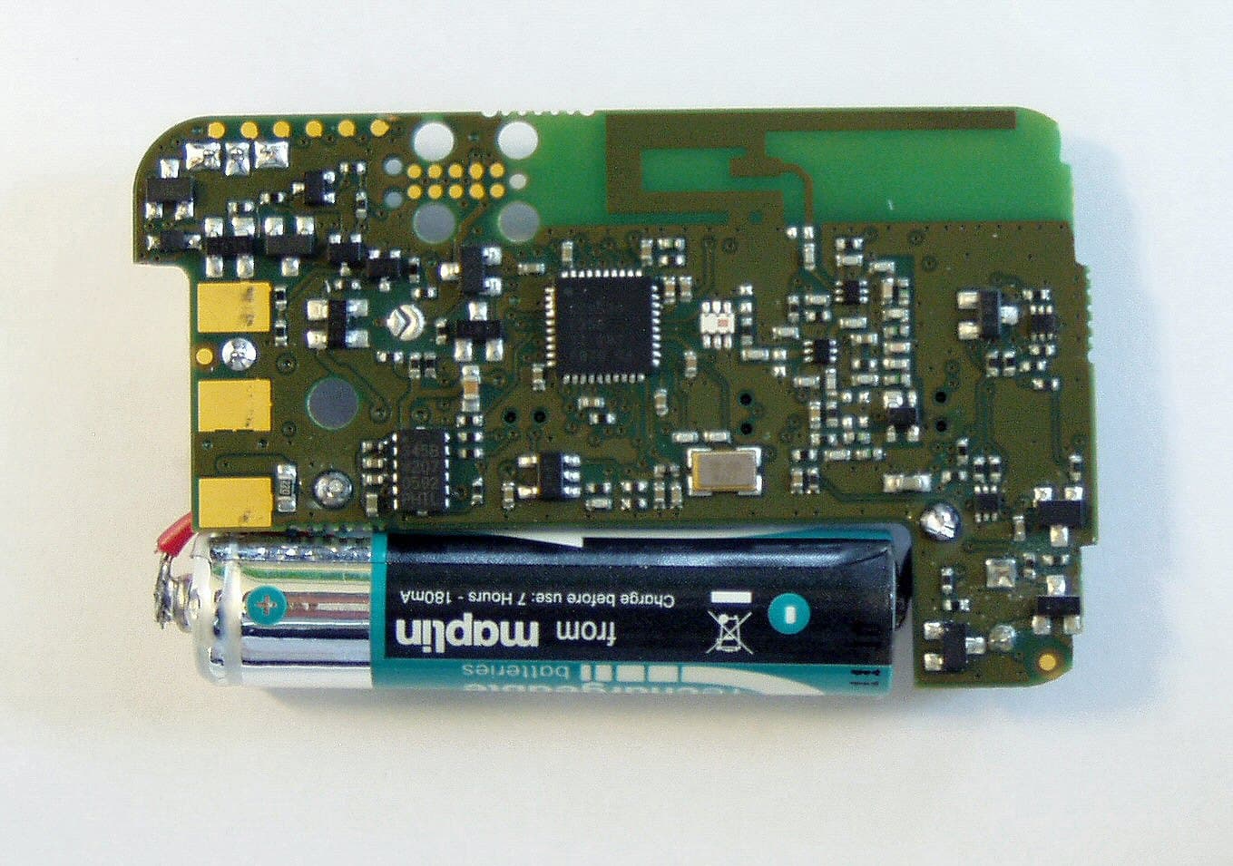
E86EKOFOB
Apr 10, 20132 way alarm and alerting device
Equipment Class
DTS - Digital Transmission System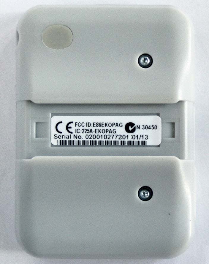
E86EKOPAG
Apr 02, 2013Alpha-numeric 2 way alarm and paging device
Equipment Class
DTS - Digital Transmission System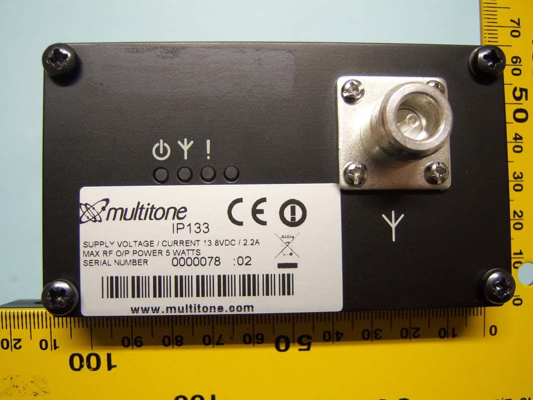
E86IP133
Feb 07, 2012Multitone I-Page � IP133
Equipment Class
TNB - Licensed Non-Broadcast Station TransmitterE86RPT503
Aug 07, 2008UHF Paging Transmitter
Equipment Class
TNB - Licensed Non-Broadcast Station Transmitter