E9U05866001T1RFID Reader/Writer
HID Global Corporation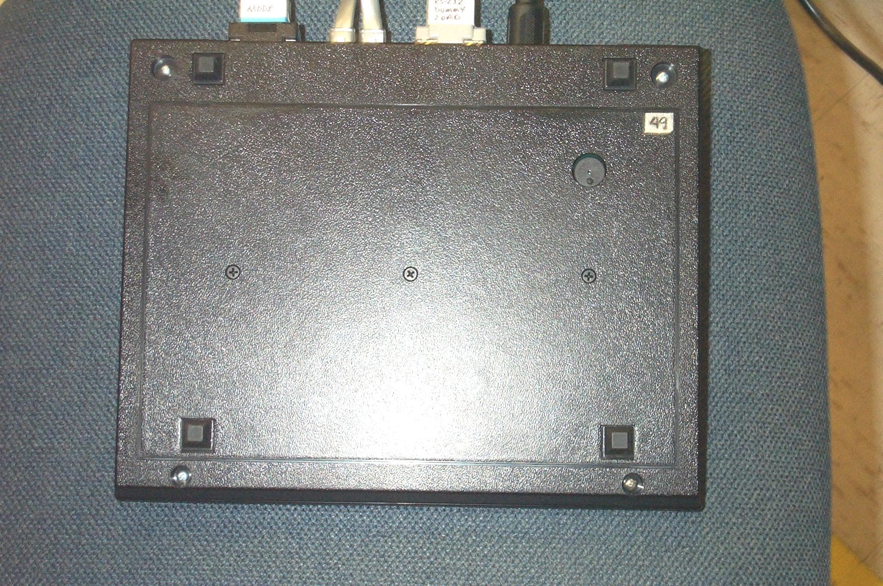
Click to zoom
Application Details
- Equipment Class
- DCD - Part 15 Low Power Transmitter Below 1705 kHz
- Date of Grant
- Jun 11, 2001
- Application Purpose
- Original Equipment
- Date of Application
- Jun 11, 2001
- Equipment Note
- RFID Reader/Writer
- Frequency Range
- 0.12500000 - 0.12500000
- Company
- HID Global Corporation
- Country
- United States
Documents & Files
Document Text
Text extracted from the exhibit documents filed with the FCC. Open a document above to read the original.
Users Manual
Integrated Information Systems Group 8201 E. McDowell Road Scottsdale, AZ 85 252-1417 Exhibit 8 Page 1 of 21 FCC ID: E9U05866001T1 5/24//01 Exhibit 8 – Users Manual BiStatix BDR-1000 RFID Tag Reader/Programmer FCC ID: E9U05866001T1 Model No. BDR-1000 8.0 BDR-1000 Users Manual May 4th,2001 K01994-001 Rev 2 BiStatix TM Desktop Reader / Writer BDR-1000 Operation Manual May 4th, 2001 K01994-001 Rev 2 2 Copyright, Trademarks, and Patent Provisions: © 2000 Motorola Corporation, reserves all rights including patents, copyrights, trademarks, trade names, and all other intellectual property rights worldwide. No reproduction, adaptation or translation is allowed without prior written permission from Motorola Corporation. Motorola Corporation reserves the right to change any product description and or specification contained here without prior notice. BiStatix products are covered under one or more of the following patents: 6,018,299; 6,040,773; 6,091,332; 6,094,138; 6,107,920; 6,107,921; 6,130,613; 6,147,605; 6,157,300; 4,818,855; 5,099,277; 5,221,831; 5,600,683; 6218942. Others are available and pending worldwide. FCC Compliance: This equipment has been tested and found to comply with the limits for a Class B digital device, pursuant to Part 15 of the FCC Rules. These limits are designed to provide reasonable protection against harmful interference in an installation. Changes or modifications not expressly approved by the party responsible for compliance could void the user’s authority to operate the equipment. This equipment generates, uses and can radiate radio frequency energy and if not installed and used in accordance with instruction, may cause harmful interference to radio communications. However, there is no guarantee that interference will not occur in a particular installation. If this equipment does cause harmful interference to radio or television reception, which can be determined by turning the equipment off and on, the user is encouraged to try to correct the interference by one or more of the following measures: • Re-orient or relocate the receiving antenna. • Increase the separation between the equipment and receiver. • Connect the equipment into an outlet on a circuit different from that to which the receiver is connected. • Consult the dealer of an experienced radio/TV technician for help. Any change or modification to this product voids the user’s authority to operate per FCC Part 15 Subpart A Section 15.21 regulations. CE This product, when marked with the CE symbol, complies with the European Community Council Directives 89/336/EEC and 99/5/EC R&TTE provided the installer/user adheres to the instructions detailed in this manual. This product, when marked with the CE symbol, is in compliance with EN 300 330, ESTI EN 300 683 with the referenced standards EN 55022 (Class B), EN 61000-4-2, EN 61000-4-3, EN 61000-4-4, EN 61000-4-6, and the Low Voltage Directive EN 60950. May 4th, 2001 K01994-001 Rev 2 3 Thank you for purchasing the Motorola BiStatix TM BDR-1000 or BDK-1000. We hope the tools are fruitful in your technology evaluation. YOUR DEVELOPMENT TOOLS... The BDR-1000 is the BiStatix Desktop Reader / Writer. The BDK-1000 is the BiStatix Development Kit, which contains a BDR-1000, DLL’s, an API and a tag kit. The BDK-1000 kit enables further evaluation of BiStatix capacitively coupled RFID technology, expanding the capabilities beyond reading tags, enabling you to construct your own tags, experiment with various tag form factors, program custom data utilizing the provided API and DLL’s and build upon sample code. Using the BDR-1000 hardware, the user may experiment with two fundamental versions of the technology – DiPole and MonoPole coupling. The hardware supports either RS-232, RS-422 or RS-485 serial communication interfaces. Contents: Item Description BDR-1000 BDK-1000 1 BDR-1000 BiStatix Desktop Reader / Writer √ √√ √ √ √√ √ 2 Universal Power Supply √ √√ √ √ √√ √ 3 Standard U.S. Power Cord √ √√ √ √ √√ √ 4 European Power Cord √ √√ √ √ √√ √ 5 RS-232 serial communication cable √ √√ √ √ √√ √ 6 This introduction / manual √ √√ √ √ √√ √ 7 CD with API, DLL’s, sample code & soft copy software instruction set √ √√ √ 8 10-pack letter-sized “Tear-It” tags √ √√ √ 9 10-pack index card-sized cards √ √√ √ 10 40-pack letter-sized electrode sheets √ √√ √ 11 Roll of (100) interposers √ √√ √ May 4th, 2001 K01994-001 Rev 2 4 Table of Contents 1 PRODUCT SPECIFICATION ................................................................................ 6 2 INTRODUCTION ..................................................................................................... 8 2.1 Theory of Operation ............................................................................................ 8 2.2 Getting Familiar with the BDR-1000 (Tag Orientation) .................................... 9 2.3 BDR-1000 Rear Panel....................................................................................... 10 3 INSTALLATION & WIRING ............................................................................... 11 3.1 Setup .................................................................................................................. 11 3.2 Host Interface Wiring........................................................................................ 12 3.3 Grounding Requirements .................................................................................. 12 4 OPERATION........................................................................................................... 13 4.1 Reader Operation .............................................................................................. 13 4.2 Programmer Operation..................................................................................... 13 4.3 Indicators .......................................................................................................... 14 5 BDR-1000 CONFIGURATION PARAMETERS ......................................…
Text truncated - open the document above for the full version.
Attestation Statements
Integrated Information Systems Group 8201 E. McDowell Road Scottsdale, AZ 85252-1417 Exhibit 2 Page 1 of 1 FCC ID: E9U05866001T1 5/24//01 Exhibit 2 – Attestation Statement BiStatix BDR-1000 RFID Tag Reader/Programmer FCC ID: E9U05866001T1 Model No. BDR-1000 2.0 Attestation Statement The technical data supplied with this application, having been taken under my supervision, is hereby duly certified. This is a statement of my qualifications: BSEE 1982, Northern Arizona University, Flagstaff, Arizona NARTE Certified EMC Engineer, 10 years 16 years experience in EMC Engineering design and test Signature: Name: Gil Estrella Date: 5/24/01 Position: Sr. Staff Engineer I hereby certify that the above application was prepared under my direction and that to the best of my knowledge and belief, the facts set forth in the application and accompanying technical data are true and correct. Signature: Name: Dwayne Awerkamp Date: 5/24/01 Position: EMC Department Manager
Cover Letter(s)
Integrated Information Systems Group Mail Drop H2550, 8201 E. McDowell Rd., Scottsdale, AZ 85252 CONFIDENTIALITY REQUEST CONTAINED WITHIN 24 May 2001 Intertek Testing Services (ITS), Inc. 27611 La Paz Road, Suite C Laguna Niguel, CA 92677 Attention: Annette Beaulieu – Account Manager Re: Application for Unlicensed Low Power Transmitter Certification (Part 15, Subpart C) FCC ID: E9U05866001T1 Motorola, Inc., Integrated Information Systems Group, 8201 E. McDowell Rd, Scottsdale, Arizona 85252 herein submits this application for Equipment Authorization under FCC Rule Part 15, Subpart C for this Unlicensed Low Power Transmitter, FCC ID: E9U05866001T1. This application is being submitted to ITS under the FCC Public Notice, DA 00-1223, allowing Telecommunication Certification Bodies (TCB) to certify specific equipment including Unlicensed Radio Frequency Devices under Scope A1. The BiStatix BDR-1000 Tag Reader/Programmer is manufactured by Indala Corporation, a wholly owned subsidiary of Motorola, Inc., located at 3041 Orchard Parkway, San Jose, CA 95134-2017. In addition to confidentiality for the entire application prior to grant (per 47CFR0.457(d)(1)(ii)), Motorola requests, pursuant to 47CFR0.459, post-grant confidentiality for identified sections of the filing material contained in this application with this material being withheld from public inspection following the grant of this authorization. This material includes Exhibit 4, Block Diagrams, Exhibit 5, Schematic Diagrams, and including any layout drawings. Specifically, these exhibits contain information relating to circuit function and complexity that could be of benefit to competitors. This material contains Motorola trade secrets and confidential information that is not customarily released or generally available to the public. Please contact me by telephone at (480) 441-3725, by facsimile at (480) 441-3625, or by email at [email protected] if there are any questions or additional information needed regarding this filing. Sincerely, Gil Estrella EMC Engineer Motorola IISG
Cover Letter(s)
To: Estrella Gil-P19838 Cc: Annette Beaulieu (E-mail) Subject: RE: Status of FCC ID: E9U05866001T1 Gil: Thank you for your response and the related attachments. They fully address the issues raised, and the application is now satisfactory. We wil proceed to certification shortly. Regards, Roland Gubisch ITS -----Original Message----- From: Estrella Gil-P19838 [mailto:[email protected]] Sent: Saturday, June 09, 2001 1:25 PM To: '[email protected]' Cc: Annette Beaulieu (E-mail) Subject: RE: Status of FCC ID: E9U05866001T1 Dear Mr. Gubisch, Attached are the responses to your comments on the BDR-1000 filing. Administrative 1) Updated Block Diagram is attached to this email. 2) The test setup photos have been extracted and attached as a separate file. 3) Surveillance Questionnaire is attached. Technical 1) The current H-field data had been adjusted to correct for the distance requirements specified in 15.209 rather than adjust the limit. The 9kHz to 450kHz emissions have been reduced by 80 dB (1/r^2) to correlate to the 300 m requirement. The 450 kHz to 30 MHz has been similarly reduced by 40 dB for 30 m representation. Although the graphs appears to indicate the fundamental is lower than other signals present it is not a true representation of the data. The graph is a victim of the required correction factors. Additionally, some of the signals present are ambient and un-related to the carrier. Since these ambient signals were so far down below the spec we didn't pursue. In any case, I have re-taken the data at 3 meters without any correction factors for measurement distance and, rather, adjusted the limits for this translation. I've updated the Test Report, Revision A, with the new graph and associated carrier level information to confirm that there are no emissi! ! ons higher than the fundamental frequency. I hope I have satisfactorily addressed your questions. Please feel free to contact me, however, if you need further information or have additional questions. Thank you very much. Regards, Gil Estrella Motorola IISG 8201 E. McDowell Rd. M/S H2550 Scottsdale, AZ 85252 Phone: 480-441-3725 Pager: 602-360-4001 Fax: 480-441-3625 EMail: [email protected] <<BDR1000_BLKDG2.pdf>> <<Test Setup Photos.pdf>> <<TCB_Surveillance.pdf>> <<Exhibit 06 Test Report_BDR1000_RevA.pdf>> -----Original Message----- From: [email protected] [mailto:[email protected]] Sent: Friday, June 08, 2001 10:25 AM To: Gil.Estrella Cc: [email protected] Subject: Status of FCC ID: E9U05866001T1 << File: TCBsurveillance_questionnaire.dot >> Gil: Administrative and technical review of your TCB certification application have been completed. The following are noted: ADMINISTRATIVE 1) Block diagram - needs to show frequencies of any oscillators in blocks, per 2.0133(b)(5); please amend. 2) Test setup photos - we must upload them to FCC database as a separate file; please extract them from the test report and provide as separate file. 3) Surveillance questionnaire - this is specific to each product; please complete and submit a new one; a blank is attached. TECHNICAL 1) Your Form 731 specifies the operating frequency as 125 kHz. The test report (Exhibit 6 appendix A) shows emissions exceeding the fundamental at all frequencies above 500 kHz. Part 15 section 15.209(c) prohibits any unwanted emission from exceeding the fundamental. Please review your designation of operating frequency, or the filtering methods used. In accordance with our certification procedures, you may exercise any one of the following choices: a) Respond within 90 days to the issues raised above. If all issues are resolved within that time, the application will be promptly granted. b) Withdraw the application. You may re-submit a revised application under the same or different FCC ID. c) Do nothing. After 90 days the application will be dismissed without prejudice, and you may re-apply at any time, using the same or different FCC ID. Please feel free to contact me for discussion of this application, and/or to correct any errors you believe may have been made in the evaluation. Sincerely, Roland W. Gubisch Chief Engineer, EMC and Telecom Intertek Testing Services NA Inc. 70 Codman Hill Road Boxborough, MA 01719 tel 978-635-8500 direct fax 978-263-7086 email [email protected] <mailto:[email protected]> <<TCBsurveillance_questionnaire.dot>> E-mail Confidentiality Disclaimer This e-mail message may contain privileged or confidential information. If you are not the intended recipient, you may not disclose, use, disseminate, distribute, copy or rely upon this message or attachment in any way. If you received this e-mail message in error, please return by forwarding the message and its attachments to the sender. Intertek Testing Services NA Inc., its subsidiaries and affiliates, do not accept liability for any errors, omissions, corruption or virus in the contents of this message or any attachments that arise as a result of e-mail transmission.
External Photos
Integrated Information Systems Group 8201 E. McDowell Road Scottsdale, AZ 85252-1417 Exhibit 3 Page 1 of 3 FCC ID: E9U05866001T1 5/24//01 Exhibit 3 – External Photographs BiStatix BDR-1000 RFID Tag Reader/Programmer FCC ID: E9U05866001T1 Model No. BDR-1000 3.0 External Photos Figure 3.0-1 BDR-1000 External View - Front Integrated Information Systems Group 8201 E. McDowell Road Scottsdale, AZ 85252-1417 Exhibit 3 Page 2 of 3 FCC ID: E9U05866001T1 5/24//01 Figure 3.0-2 BDR-1000 External View - Rear Integrated Information Systems Group 8201 E. McDowell Road Scottsdale, AZ 85252-1417 Exhibit 3 Page 3 of 3 FCC ID: E9U05866001T1 5/24//01 Figure 3.0-3 BDR-1000 External View – Bottom
ID Label/Location Info
Integrated Information Systems Group 8201 E. McDowell Road Scottsdale, AZ 85252-1417 Exhibit 1 Page 1 of 2 FCC ID: E9U05866001T1 5/24//01 Exhibit 1 – ID Label Information BiStatix BDR-1000 RFID Tag Reader/Programmer FCC ID: E9U05866001T1 Model No. BDR-1000 1.0 Identification (Nameplate) Information Exhibit 1 Page 2 of 2 FCC ID: E9U05866001T1 5/24/01 Figure 1.0-1 BDR-1000 FCC label Display (placed on bottom of unit)
Internal Photos
Integrated Information Systems Group 8201 E. McDowell Road Scottsdale, AZ 85252-1417 Exhibit 9 Page 1 of 2 FCC ID: E9U05866001T1 5/24//01 Exhibit 9 – Internal Photographs BiStatix BDR-1000 RFID Tag Reader/Programmer FCC ID: E9U05866001T1 Model No. BDR-1000 9.0 Internal Photographs Figure 9.0-1 BDR-1000 Internal View – Control Board Integrated Information Systems Group 8201 E. McDowell Road Scottsdale, AZ 85252-1417 Exhibit 9 Page 2 of 2 FCC ID: E9U05866001T1 5/24//01 Figure 9.0-2 BDR-1000 Internal View – Antenna Board
Operational Description
Integrated Information Systems Group 8201 E. McDowell Road Scottsdale, AZ 85252-1417 Exhibit 12 Page 1 of 2 FCC ID: E9U05866001T1 5/24//01 Exhibit 12 – Operational Description BiStatix BDR-1000 RFID Tag Reader/Programmer FCC ID: E9U05866001T1 Model No. BDR-1000 12.0 Operational Description The BDR-1000 is a BiStatix TM Radio Frequency Identification (RFID) device. The product is capable of either reading or programming RFID tags. The primary intent is that this product be used as a Development Station for the design of paper BiStatix TM cards and tags. This technology utilizes Electric Fields and Capacitance coupling to complete the RF link between the electronics module and the identification device. The following is a basic theory of the internal operation of the BDR-1000 based upon the attached block diagram. Input Power and Conditioning: Power is applied to the electronics module from an inline AC Universal Power Supply. The supply delivers +/- 12 volts and 5 volts DC through a 5-pin DIN connector located on the connector panel of the enclosure. Micro Controller and Digital System: An internal micro controller is used to control all serial communication to and from a host controller. It is also used to demodulate the signal that is received from the RFID tag as well as control both a LED and beeper used to provide user feedback. Auxiliary Inputs, Outputs and Switches: The enclosure connector panel consists of an on/off switch and various other connectors. The DB9 is a standard RS232 I/O used to communicate with a host controller. In addition a Dual RJ45 connect is available for use with RS485 if so required. A DB15 connector is also available that will support external connectors in the future but at this time is not active. Finally the upper top of the face contains a LED that is used along with an internal beeper to provide feedback to the user for both read and write operations. Antenna Plates: Receiver and exciter antennas are contained on the antenna PCB. This PCB is mounted just beneath the label on the enclosure. The exciter antenna is the source plate for capacitive coupling to the RFID tag and provides the 125 kHz excitation signal. The receiver antenna is the receive plate for the RFID tag and receives an AM (at 62.5 kHz) exciter signal. Integrated Information Systems Group 8201 E. McDowell Road Scottsdale, AZ 85252-1417 Exhibit 12 Page 2 of 2 FCC ID: E9U05866001T1 5/24//01 Demodulation and Receiver Amplifier: The receiver signal picked up by the receiver antenna is fed to the Receiver Amplifier. This amplifier amplifies the 62.5 kHz AM signal and rejects the 125 kHz exciter component. The output of the receiver amplifier is then fed to the internal controller for BPSK demodulation.
RF Exposure Info
Integrated Information Systems Group 8201 E. McDowell Road Scottsdale, AZ 85252-1417 Exhibit 11 Page 1 of 20 FCC ID: E9U05866001T1 5/24//01 Exhibit 11 – RF Exposure Information BiStatix BDR-1000 RFID Tag Reader/Programmer FCC ID: E9U05866001T1 Model No. BDR-1000 11.0 RF Exposure Information The BDR-1000 RFID Tag Reader/Programmer complies with human radiation emission requirements. These requirements are based on the Maximum Permissible Exposure (MPE) levels of ANSI/IEEE C95.1-1992 and 47 CFR 1.1310, Table 1 for an uncontrolled environment. The access control reader is a low power device intended to be used as a desktop device. The access control reader can arguably fit the definition of a portable device as defined in 47 CFR 2.1093(b) (i.e. "designed to be used so that the radiating structure of the device is within 20 cm of the body of the user", specifically the hand). However, it does not fit any of the equipment classification criteria for portable devices requiring SAR testing as defined in 47 CFR 2.1093(c). All other portable transmitting devices "are categorically excluded from routine environmental evaluation for RF exposure prior to equipment authorization or use" per 2.1093(c) which includes the Access Control Reader. An Evaluation of Electric and Magnetic Fields and Induced and Contact Currents Associated with Operation of the Motorola BiStatix™ BDR-1000 Access Control Reader May 15, 2001 Prepared for Indala Corporation A Subsidiary of Morotorla (WSSD) 3041 Orchard Parkway San Jose, CA 95134-2017 by Richard A. Tell Richard Tell Associates, Inc. 3433 Ringstar Road, Suite 3 North Las Vegas, NV 89030 R ICHARD T ELL A SSOCIATES , INC. (702)645-3338 ! FAX(702)645-8842 ! 3433 Ringstar Rd., Suite 2 ! N. Las Vegas, NV 89030 An Evaluation of Electric and Magnetic Fields and Induced and Contact Currents Associated with Operation of the Motorola BiStatix™ BDR-1000 Access Control Reader Introduction Motorola's Indala Corporation has developed an electric field based radiofrequency identification (RFID) system based on Motorola's BiStatix™ technology. The BiStatix™ technology, employed with RFID tags (miniature transponders), can be used for monitoring and tracking packages, parcels, freight and other items. This technology makes use of very low frequency (VLF) electric fields at 125 kHz. The Model BDR-1000 reader unit was evaluated in the measurements reported here to assess compliance with applicable human exposure limits for electric and magnetic fields. The BDR-1000 Access Control Reader is contained within a modest sized structure measuring nominally 8.0 x 10.0 inches and is to be placed on a counter or desk with the internal active electrode horizontal in orientation. Figure 1 shows the BDR-1000 unit. This report documents a series of measurements to evaluate potential exposure of personnel to electric and magnetic fields produced by this reader and the induced body currents and contact currents that may result from personnel occupying areas near the reader or handling the reader. Method of Evaluation RF Fields Radiofrequency (RF) fields were examined by measuring the spatial variation of electric and magnetic field strengths in the vicinity of the reader. This was accomplished by determining the resultant field strength from three orthogonal components of the field consisting of the vertical (z), and horizontal (x,y) polarization components. The reader unit was placed on a wooden support placing it 79 cm above the floor to simulate a typical installation. Figure 2 shows the test setup with the reader placed on a wooden desk (the reader is hidden from view in this figure by the cardboard measurement plane). To facilitate the field measurements, a measurement grid was drawn on the surface of a large cardboard sheet. The cardboard sheet was attached to the front edge of the desk such that the specific measurement points were positioned at the locations specified in the CENELEC standard. The reader unit was positioned on the desk, on top of a wooden support, to place at successively greater distances of 15, 30 and 45 cm from the center of the measurement probe used for measuring electric and magnetic fields. The test area was positioned over a concrete floor. The reader was powered by connection to an external power supply that was connected to a 120 volt AC outlet. The power cable to the reader was positioned to lead BiStatix™ BDR-1000 RF Compliance Measurements, page 2 directly away, in a straight line, from the rear of the unit for approximately 28 inches (approximately 71 cm) before dropping to the floor. Two identical models of the BDR- 1000 reader were submitted for evaluation and field strength and contact current measurements were performed on both. Electric and magnetic fields were measured in two different ways. The first method followed guidance contained in IEEE C95.1-1999 for obtaining the spatially averaged field strength. 1 In this case, three mutually orthogonal values of field strength were obtained at 15-cm intervals beginning at approximately 15 cm above the floor and extending up to a height of 175 cm. These measurements were made at a lateral distance of 15 cm directly in front of the reader assembly front surface. The spatially averaged fields were then computed by taking the average of the individual resultant values of fields at each measurement height following the recommendations in the IEEE standard. 2 Figure 2 shows the measurement setup for measurement of fields along the 175 cm long, vertical line. A second approach to field measurements followed the recent Final Draft Rev. 2.4 from CENELEC designed for evaluation of human exposure to devices used in such applications as RF identification. 3 It was deemed important to also use this measurement protocol as it specifically states that it is applicable to determining compliance with the exposure guidelines published by the International Commission on Non-Ionizing Radiation Protection (ICNIRP). 4 The ICN…
Text truncated - open the document above for the full version.
Test Report
Integrated Information Systems Group 8201 E. McDowell Road Scottsdale, AZ 85252-1417 Report No. 91007-00226-01 Exhibit 6 Page 1 of 26 FCC ID: E9U05866001T1 Revision A 6/09/01 Exhibit 6 – Test Report BiStatix BDR-1000 RFID Tag Reader/Programmer FCC ID: E9U05866001T1 Model No. BDR-1000 Equipment Manufacturer: Indala Corporation (subsidiary of Motorola, Inc.) 3041 Orchard Parkway San Jose, CA 95134 Tests Conducted By: Motorola IISG EMC Test Facility 8201 E. McDowell Rd. Scottsdale, Arizona 85252 Tests Period: April 10 th to April 20 th , 2001 Test Summary: Complies with FCC Part 15, Subpart C, Unlicensed Low Power Transmitters The Motorola SSG EMC/TEMPEST Laboratory is accredited through the NVLAP Lab Code 100405-0 This document shall not be reproduced, except in full, without the written approval of the laboratory. This document shall not be used by the client to claim product endorsement by NVLAP or any agency of the U.S. Government. Exhibit 6 Page 2 of 26 FCC ID: E9U05866001T1 Revision A 6/09/01 6.0 Introduction 6.0.1 Product Description The Motorola BiStatix BDR-1000 is a Radio Frequency Identification device (RFID). The product is capable of either reading or programming RFID tags. The primary intent is that this product be used as a Development Station for the design of paper BiStatix cards and tags. This technology utilizes Electric Fields and Capacitance coupling to complete the RF link between the electronics module and the identification device. The reader outputs data in Wiegand, ABA Track II, magnetic stripe or RS-232C formats, making it easy to upgrade an existing site to proximity using the wiring already in place. Product Specifications: Frequency of Operation -Excitation 125 kHz Typical -Data Carrier 62.5 kHz Typical -Data Rate 7.8125 kbits/second Typical Exhibit 6 Page 3 of 26 FCC ID: E9U05866001T1 Revision A 6/09/01 6.0.2 Facility Description EMI testing of the BDR-1000 Reader/Programmer was performed at the Motorola Integrated Information Systems Group’s (IISG) EMI/TEMPEST Test Laboratory. This test laboratory is located in the southeast wing of the Hayden building at 8201 E. McDowell Road, Scottsdale, AZ. Motorola IISG Test Facility Address: Motorola, Inc. Integrated Information Systems Group Hayden EMC Facility 8201 E. McDowell Rd. M/D H2550 Scottsdale, AZ 85252 The facility has been found to be in compliance with the requirements of Section 2.948 of the FCC rules, per FCC letter 31040/SIT, 1300F2, dated October 6, 1998. The facility has also been issued a Certificate of Accreditation through the National Voluntary Laboratory Accreditation Program (NVLAP) by NIST. This is under NVLAP Code: 100405-0 and is effective through September 30, 2001. 6.0.3 Quality System The EMI/TEMPEST Test Laboratory maintains a Quality Manual that describes the quality assurance program of the EMC/TEMPEST Facility to set forth procedures covering all quality assurance functions. This manual has been constructed to reflect a quality program in compliance with the requirements of the following: • National Institute of Standards & Technology (NIST) National Voluntary Laboratory Accreditation Program (NVLAP) • NIST/NVLAP EMC MIL-STD 462 Program Handbook (Apr. 1994) • NVLAP EMC and Telecommunications FCC Methods Handbook 150-11 (Apr. 1995) • MIL-Q-9858A, MIL-STD 461, 462, 463, 461D, 462D • National Security Agency Technical and Security Requirements Document for the Endorsed TEMPEST Test Services Program, NSA TSRD No. 88-8B, 5 Oct. 1993 • System Solution Group of Motorola Quality Six Sigma Program. 6.0.4 Standard References 47 CFR 2 Code of Federal Regulations, Title 47, Part 2, “Frequency Allocations and Radio Treaty Matters; General Rules and Regulations” 47 CFR 15 Code of Federal Regulations, Title 47, Part 15, “Radio Frequency Devices” Subpart C, "Intentional Radiators" C63.4-1992 American National Standards Institute (ANSI), “Methods of Measurement of Radio-Noise Emissions from Low-Voltage Electrical and Electronic Equipment in the Range of 9 kHz to 40 GHz” Exhibit 6 Page 4 of 26 FCC ID: E9U05866001T1 Revision A 6/09/01 6.1 Test Procedures 6.1.1 Requirements The BDR-1000 reader/programmer is subject to FCC Part 15, Subpart C and Part 2 for FCC Certification for units marketed within the United States. The following tests, as specified in FCC Part 2, with limits as defined in FCC Part 15, and shown in Table 6.1-1 below were performed on the access control reader. Table 6.1-1 Tests Required for Certification of the 125 kHz BDR-1000 Reader/Programmer Te s t P a r a me t e r FCC Part 2 Paragraph Number FCC Part 15 Paragraph Number FCC Part 15 Limit Field Strength of Spurious Emissions Restricted Bands of Operation AC Conducted Emissions 2.1053 15.209 15.205 15.207 Freq (MHz) Limit ( uV/m) d (m) .009-0.490 MHz 2400/F(kHz) 300m 0.490-1.705 MHz 24000/F 30 m 1.705-30 MHz 30 30 m 30-88 MHz 100 3 m 88-216 MHz 150 3m 216-960 MHz 200 3m Above 960 MHz 500 3m Does not operate in any restricted bands; Spurious requirements same as 15.209 47.95 dBuV 6.1.2 Operational Configuration The BDR-1000 RFID Tag Reader/Programmer was tested in its typical operational configuration. The BDR-1000 unit was set up and operated in a continuous transmit mode at the frequency of 125 kHz and at its maximum rated output power for all tests. All testing was done in a radiated test setup since the antenna is an integral part of the unit. The RS-485 interface was looped back into itself using the dual RJ45 interfaces on the back of the unit. The RS-232 was terminated into the connector load provided. A general test setup is shown as Figure …
Text truncated - open the document above for the full version.
Contact Information
Applicant
Frank de Vall(Sr. Manager - Compliance Engineering)
Technical Contact
Motorola IISGGil Estrella
[email protected]480-441-3725
8201 E. McDowell Rd. · Scottsdale, Arizona · United States
Non-Technical Contact
Motorola IISGGil Estrella
480-441-3725
Test Firm
General Dynamics C4 SystemsHarry Gaul
Technical Specifications
| # | Rule Parts | Frequency Range | Power Output |
|---|---|---|---|
| 1 | 15C | 0.125 MHz - 0.125 MHz | - |
Other Applications from HID Global Corporation
E9UASR620PLUSPLUS
May 30, 2006ASR-620++ Long Range Reader
Equipment Class
DCD - Part 15 Low Power Transmitter Below 1705 kHz
E9UX200
May 30, 2005X200 Series
Equipment Class
DXX - Part 15 Low Power Communication Device Transmitter
E9UCX-8525
Jun 04, 2003Proximity Reader, CX-8525
Equipment Class
DXX - Part 15 Low Power Communication Device Transmitter
E9UARK501
Sep 15, 2002Flexpass Keypad Reader
Equipment Class
DXX - Part 15 Low Power Communication Device Transmitter
E9UOFR100
Aug 19, 2001PROXIMITY READER
Equipment Class
DCD - Part 15 Low Power Transmitter Below 1705 kHz