E9UX200X200 Series
HID Global Corporation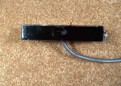
Click to zoom
Application Details
- Equipment Class
- DXX - Part 15 Low Power Communication Device Transmitter
- Date of Grant
- May 30, 2005
- Application Purpose
- Original Equipment
- Date of Application
- May 30, 2005
- Equipment Note
- X200 Series
- Frequency Range
- 13.56000000 - 13.56000000
- Company
- HID Global Corporation
- Country
- United States
Documents & Files
Document Text
Text extracted from the exhibit documents filed with the FCC. Open a document above to read the original.
Users Manual
K02017-000 Rev. A 1 Readers Installation Guide K02017-000 Rev. A 2 1.0 Overview 1.1 Introduction The FlexSmart Slim readers’ use the same reader electronics module. A reader can easily be configured at the site because the readers’ bezels can be interchangeably snapped on the common reader module. The following is a quick installation procedure. The FlexSmart Arch and Wave readers mount on any North American standard electrical gang box or on any flat surface, with snap on bezels. See pages 5 and 6. 1.2 Unpacking and Identifying Supplied Parts Unpack the contents and become familiar with the components. The following items will be included with FlexSmart readers: 1. Installation guide. 2. FlexSmart reader module for Slim or Wallswitch and Midrange. 3. Front Bezel. 1.3 Identifying the Reader Format The reader format is typed on the ID label (see figure) on the reader electronics module. 2.0 Installation 2.1 Mechanical Installation Refer to pages 6 for reader style. 2.1.1 Mullion Mounting FlexSmart Wave and Arch, Slim readers mount to a mullion by drilling drill two holes 6-32 or M-3 sheet metal or thread forming screws 3.3” (8.38 cm) apart. Locate and drill a 0.375” (0.95 cm) hole for the reader cable per page 6 for Wave and Arch respectively. Route the cable through the center hole to the controller. Using the two 6-32 or M-3 screws attach the reader to the first two mounting holes. Once the reader module is screwed in place, snap on the, Arch or Wave bezel. 2.1.3 Removing Front Bezel Remove Wave bezels using a strong paper clip. Hook the paper clip onto the latch and pull downwards to release it. Remove Arch bezels by pressing a pointed object into the bottom holes of the enclosure to release the latches. 2.2 Power Supply Cable Types and Maximum Lengths The FlexSmart readers require a minimum voltage of 9.0 VDC. Voltage drops, caused by the cable resistance, can be made up by increasing the power supply voltage (DO NOT SET THE POWER SUPPLY VOLTAGE TO HIGHER THAN 16 VDC). The following are the recommended cable types and maximum cable lengths for cable connecting the power supply to the reader (DO NOT USE CABLES WITH GAUGES SMALLER THAN 24 AWG): K02017-000 Rev. A 3 Cable Type Maximum Cable Length 24 AWG (0.60mm), three conductors, with an overall foil shield, 9533 or equivalent. 200’ (61 m) 22 AWG (0.80mm), two conductors, with an overall foil shield, Alpha 5192 or equivalent. 300’ (91 m) 18 AWG (1.20mm), two conductors, with an overall foil shield, 5836 or equivalent. 500’ (152 m) 2.2.1 Reader to Host Interface Wire Types and Lengths Refer to the table below to determine the recommended wiring type at various maximum distances. Variation in distance requires different wire gauges, Because of system data termination differences, contact your system manufacturer for its exact requirements, Installation to be in accordance with National Electric Code ANSI/NFPA 70. Cable Type Maximum Cable Length 22 AWG (0.80mm), six or eight conductor, with an overall foil shield, Alpha 5196, 5198 or equivalent. 500’(152 m) 18 AWG (1.20mm), six or eight conductor, with an overall foil shield, Alpha 5386, 5388 or equivalent. 500’ (152m) Readers Power Supply Cable Length Readers Host Cable Length K02017-000 Rev. A 4 2.3 Electrical Installation 2.3.1. Grounding Connect the reader directly to an earth ground. An earth ground can be established by driving a copper clad ground rod into the earth. Make certain the DC resistance between your established earth ground and the system ground is 50 Ohms or less. If direct connection to a ground rod is not possible, connect the reader to an earth grounded cold water metal pipe (do not connect to copper fire sprinkler system because it may have non-conductive couplings) or steel frames (building beams) that connect to earth. Prevent ground loops by connecting both the cable shield and the negative line of the power supply to one common earth ground point. Connecting different points to separate earth grounds may result in a ground loop. Ground loops may cause poor read range and communication line interference resulting in no code or improper code being seen by the controller. In a multiple reader installation, connect all readers to a single earth ground reference point (common ground). 2.3.2. Reader to Host Interface Wiring Choose the appropriate interface for your installation. K02017-000 Rev. A 5 Notes: • The system must have a single earth ground point. • As shown above, do not connect shield (screen) wire at FlexSmart reader cable splice. • For open collector (non-terminated output), consult your system manufacturer for correct cable length and type. 3.0 Operation When power is first applied to the reader, it performs an internal circuit Self Test™. If it appears to be functioning properly, the reader will flash the amber LED and beep twice. After the Self Test™ is completed, the reader is in a READY status mode and you may present the card to the reader. 3.1 Presenting the Card To obtain maximum read range, present the card to the reader, keeping the card parallel to the FlexSmart reader, move it slowly toward the face of the reader until a QuickFlash™ (refer to section 3.3) is obtained. This is the point at which the card is read and the data is transmitted to the controller. To read the card again, remove it from the antenna field and present it again. During normal use, the card can be presented to the antenna at any angle, although this will result in a reduced read range. 3.2 Data Output The readers are capable of outputting in either Wiegand or magnetic stripe formatted data. For further information please call technical support at (800) 779-8663 4.0 Regulatory Statements 4.1 FCC This device complies with part 15 of the FCC rules. Operation is subject to the following two conditions: (1) this device may not cause harmful interference, and (2) this device must accept any interference received, including interference that may cause undesired operation. Changes…
Text truncated - open the document above for the full version.
Cover Letter(s)
13.56 MHz Slim and Wall Switch Product Families ModelNameType (tt)Style (s)Color (c) MX200-ttscfMifare Reader01 = Slim1 = Wave1 = Black DX200-ttscfDesfire Reader02 = Wall Switch2 = Curve2 = Blue IX200-ttscfISO 15693 Reader03 = N/A3 = Arch3 = Gray SX200-ttscfSerial Number Reader04 = N/A4 = Linear4 = Biege PX200-ttscf13.56 Reader05 = N/A5 = Euro0 = Module 06 = OEM Basic0 = Module 07 = OEM Full 00 = Module Model numbers representType, Style, and Color Represent the different software selectable featuredecoritive Bezel options. Sets within the reader software. 05-12-05 Format (f) A = Wiegand B = Buffered C = Magstripe D = 8 Bit Burst E = 4 Bit Burst F = Custom S = Serial Format represents the software selectable data formats.
Cover Letter(s)
Response to E05-000161-1 and E05-000161-1 IC E05-000161-1 1-3. A revised manual has been uploaded. 4. The band edge measurements are included in the 15.225 emissions mask on page 11. E05-000161-1 IC 1. A revised manual has been uploaded.
External Photos
SUBMITTAL PHOTOGRAPH External Front Potted SUBMITTAL PHOTOGRAPH External Back Potted SUBMITTAL PHOTOGRAPH External Top Potted SUBMITTAL PHOTOGRAPH External Bottom Potted SUBMITTAL PHOTOGRAPH External Left Potted SUBMITTAL PHOTOGRAPH External Right Potted
Internal Photos
Page 1 of 6 Report No.: ETS05-002A SUBMITTAL PHOTOGRAPH Un-Potted Front Page 2 of 6 Report No.: ETS05-002A SUBMITTAL PHOTOGRAPH Un-Potted Back Page 3 of 6 Report No.: ETS05-002A SUBMITTAL PHOTOGRAPH Main PCB Front Page 4 of 6 Report No.: ETS05-002A SUBMITTAL PHOTOGRAPH Main PCB Back Page 5 of 6 Report No.: ETS05-002A SUBMITTAL PHOTOGRAPH Antenna PCB Front Page 6 of 6 Report No.: ETS05-002A SUBMITTAL PHOTOGRAPH Antenna PCB Back
Test Report
Page 1 of 31 Report No.: FC05-002 INDALA TEST REPORT FOR THE MIFARE READER, MX200-ttscf FCC PART 15 SUBPART C SECTIONS 15.207, 15.209, 15.225 AND RSS-210 COMPLIANCE DATE OF ISSUE: MAY 11, 2005 PREPARED FOR: Indala 6850 B Santa Teresa Blvd. San Jose, CA 95119-1205 PREPARED BY: Mary Ellen Clayton CKC Laboratories, Inc. 5046 Sierra Pines Drive Mariposa, CA 95338 P.O. No.: 14002905 W.O. No.: 83017 Date of test: January 17 - April 27, 2005 Report No.: FC05-002 This report contains a total of 31 pages and may be reproduced in full only. Partial reproduction may only be done with the written consent of CKC Laboratories, Inc. The results in this report apply only to the items tested, as identified herein. Page 2 of 31 Report No.: FC05-002 TABLE OF CONTENTS Administrative Information .............................................................................................3 FCC to Canada Standard Correlation Matrix...................................................................4 Conditions for Compliance ..............................................................................................4 Approvals .........................................................................................................................4 FCC 15.33(a) Frequency Ranges Tested .........................................................................5 FCC 15.35 Analyzer Bandwidth Settings ........................................................................5 FCC 15.203 Antenna Requirements ................................................................................5 FCC 15.205 Restricted Bands..........................................................................................5 Eut Operating Frequency .................................................................................................5 Temperature And Humidity During Testing....................................................................5 Equipment Under Test (EUT) Description ......................................................................6 Equipment Under Test .....................................................................................................6 Peripheral Devices ...........................................................................................................6 Report of Measurements ..................................................................................................7 Table 1: FCC 15.207 Six Highest Conducted Emission Levels ..........................7 Table 2: FCC 15.209 Highest Radiated Emission Levels: 9kHz to 30MHz .......8 Table 3: FCC 15.209 Six Highest Radiated Emission Levels: 30-1000MHz......9 Table 4: FCC 15.225 Fundamental Emission Levels ..........................................10 FCC 15.225 Emissions Mask...............................................................................11 Occupied Bandwidth Plot ....................................................................................12 Frequency Stability and Voltage Variations ........................................................13 EUT Setup........................................................................................................................14 Correction Factors............................................................................................................14 Table A: Sample Calculations .............................................................................14 Test Instrumentation and Analyzer Settings ....................................................................15 Spectrum Analyzer Detector Functions ...............................................................15 Peak..........................................................................................................15 Quasi-Peak ...............................................................................................15 Average ....................................................................................................15 EUT Testing.....................................................................................................................16 Mains Conducted Emissions................................................................................16 Radiated Emissions ..............................................................................................16 Appendix A: Test Setup Photographs..............................................................................17 Photograph Showing Mains Conducted Emissions .............................................18 Photograph Showing Radiated Emissions ...........................................................19 Photograph Showing Radiated Emissions ...........................................................20 Photograph Showing Temperature Testing .........................................................21 Appendix B: Test Equipment List ...................................................................................22 Appendix C: Measurement Data Sheets ..........................................................................23 Page 3 of 31 Report No.: FC05-002 ADMINISTRATIVE INFORMATION DATE OF TEST: January 17 - April 27, 2005 DATE OF RECEIPT: January 17, 2005 MANUFACTURER: Indala 6850 B Santa Teresa Blvd. San Jose, CA 95119-1205 REPRESENTATIVE: Steve Rose TEST LOCATION: CKC Laboratories, Inc. 5046 Sierra Pines Drive Mariposa, CA 95338 TEST METHOD: ANSI C63.4 (2003) and RSS-212 PURPOSE OF TEST: To demonstrate the compliance of the Mifare Reader, MX200-ttscf with the requirements for FCC Part 15 Subpart C Sections 15.207, 15.209, 15.225 and RSS-210 devices. Page 4 of 31 Report No.: FC05-002 FCC TO CANADA STANDARD CORRELATION MATRIX Canadian Standard Canadian Section FCC Standard FCC Section Test Description RSS 2105.547CFR15.203Antenna Connector Requirements RSS 2106.2.147CFR15.209General Radiated Emissions Requirement RSS 2106.2.2(e)47CFR15.225(a)* Fundamental Requirements RSS 2106.2.2(e)NANA±150kHz to ±450kHz Emissions Re…
Text truncated - open the document above for the full version.
Test Setup Photos
PHOTOGRAPH SHOWING MAINS CONDUCTED EMISSIONS Mains Conducted Emissions - Front View PHOTOGRAPH SHOWING RADIATED EMISSIONS Radiated Emissions - Front View PHOTOGRAPH SHOWING RADIATED EMISSIONS Radiated Emissions - Back View PHOTOGRAPH SHOWING TEMPERATURE TESTING
Contact Information
Applicant
Frank de Vall(Sr. Manager - Compliance Engineering)
Technical Contact
CKC Laboratories, Inc.Mary Ellen Clayton
[email protected]800-500-4362
5473-A Clouds Rest · Mariposa, California · United States
Test Firm
CKC Laboratories, Inc.Steve Behm
Technical Specifications
| # | Rule Parts | Frequency Range | Power Output |
|---|---|---|---|
| 1 | 15C | 13.56 MHz - 13.56 MHz | - |
Other Applications from HID Global Corporation
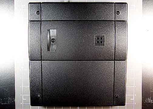
E9UASR620PLUSPLUS
May 30, 2006ASR-620++ Long Range Reader
Equipment Class
DCD - Part 15 Low Power Transmitter Below 1705 kHz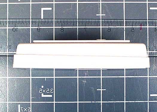
E9UCX-8525
Jun 04, 2003Proximity Reader, CX-8525
Equipment Class
DXX - Part 15 Low Power Communication Device Transmitter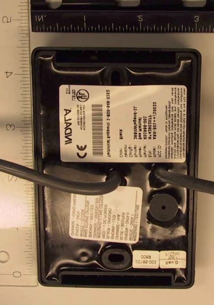
E9UARK501
Sep 15, 2002Flexpass Keypad Reader
Equipment Class
DXX - Part 15 Low Power Communication Device Transmitter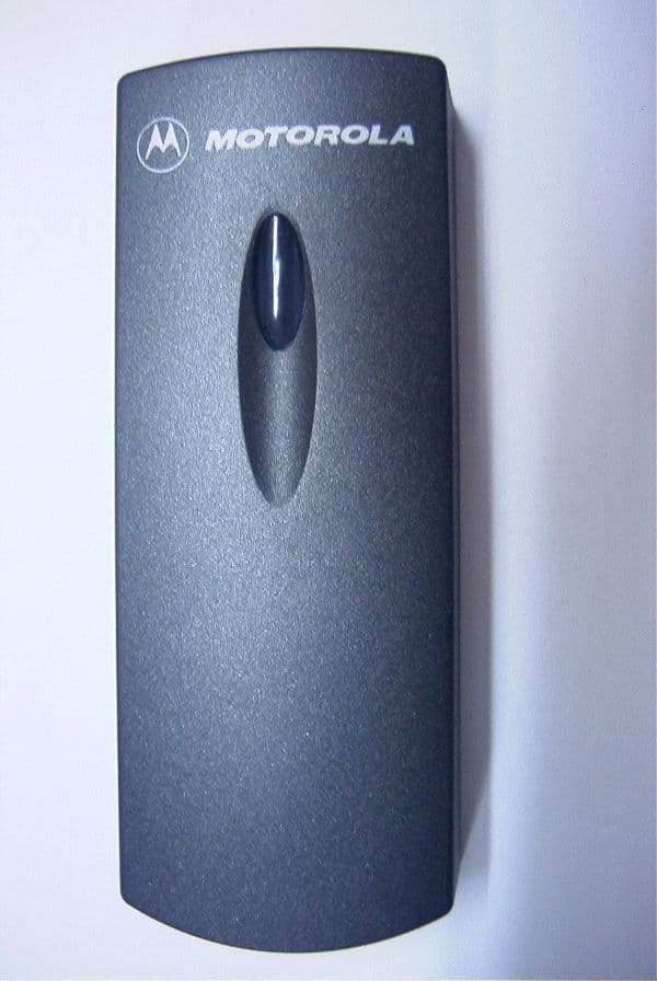
E9UOFR100
Aug 19, 2001PROXIMITY READER
Equipment Class
DCD - Part 15 Low Power Transmitter Below 1705 kHz
E9U05866001T1
Jun 11, 2001RFID Reader/Writer
Equipment Class
DCD - Part 15 Low Power Transmitter Below 1705 kHz