E9UASR620PLUSPLUSASR-620++ Long Range Reader
HID Global Corporation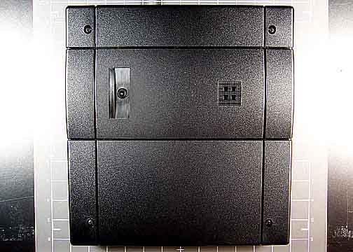
Click to zoom
Application Details
- Equipment Class
- DCD - Part 15 Low Power Transmitter Below 1705 kHz
- Date of Grant
- May 30, 2006
- Application Purpose
- Original Equipment
- Date of Application
- May 30, 2006
- Equipment Note
- ASR-620++ Long Range Reader
- Frequency Range
- 0.12500000 - 0.12500000
- Company
- HID Global Corporation
- Country
- United States
Documents & Files
Document Text
Text extracted from the exhibit documents filed with the FCC. Open a document above to read the original.
Users Manual
K02021-000 Rev A April 2006 FlexPass TM Advantage Series Proximity Plus TM ASR-620++ PowerProx TM Reader User Manual K02021-000 Rev A April 2006 ii FCC Compliance: This equipment has been tested and found to comply with the limits for a Class B digital device, pursuant to Part 15 of the FCC rules. These limits are designed to provide reasonable protection against harmful interference in a residential installation. This equipment generates, uses and can radiate radio frequency energy and, if not installed and used in accordance with the instructions, may cause harmful interference to radio communications. However, there is no guarantee that interference will not occur in a particular installation. If this equipment does cause harmful interference to radio or television reception, which can be determined by turning the equipment off and on, the user is encouraged to try to correct the interference by one or more of the following measures: • Reorient or relocate the receiving antenna. • Increase the separation between the equipment and the receiver. • Connect the equipment into an outlet on a circuit different from that to which the receiver is connected. • Consult the dealer or an experienced radio/TV technician for help. UL Listing: The ASR-620++ has been evaluated by UL to UL-294 standard and is listed under file BP6430. CE Compliance: This product complies with the European Community Council Directive 89/336/EEC and the standards specified under IETS-300-683 and IETS-300-330, if the installer/ user adheres to the instructions detailed in this manual. Notice: The ASR-620++ reader requires the use of linear, series pass power supplies. Switching power supplies are not recommended because the use of these supplies may reduce the read range. The unit is intended to be powered from a current limited power source such as an IEC/EN 60950 approved power supply. Do not use the reader’s power supply for other equipment, particularly when operating switched inductive loads such as motor control relays and solenoids (i.e., magnetic locks, latch or strike). Doing so will affect the reader operation. Use a separate dedicated power supply for Indala proximity readers. Because this technology is based on radio frequency and because nearby environmental sources of electrical interference may affect the performance of the reader, the following is a list of precautions that should be considered when installing or wiring the reader: • Metal affects radio signals. Do not cover the face of the reader with metal of any kind. • Reduce or eliminate unwanted signals from external sources. • Do not place the reader wiring bundled in conduit with AC power cables, lock power or signal wiring. K02021-000 Rev A April 2006 iii • Maintain all reader wiring a minimum distance of 12" (30 cm) away from other wiring such as AC power, computer data wiring, telephone wiring or wiring to electric locking devices, etc. • Do not install the reader in areas where sources of broad spectrum EMI noise may be present. Examples of EMI broad spectrum noise producers are motors, pumps, generators, AC-DC converters, uninterruptable power supplies, AC switching relays, light dimmers, computer monitors and CRTs. K02021-000 Rev A April 2006 iv K02021-000 Rev A April 2006 1 1.0 Overview 1.1 Introduction The ASR-620++ reader is a rugged radio frequency reader designed for applications such as identification systems, security systems and data collection. The ASR-620++ reader mounts on most flat surfaces. The reader electronics are enclosed with a gasket sealed cover to provide weather resistance. The reader outputs data in Wiegand or ABA Track II (Mag Stripe) format. An optional RS-232 interface requires the use of a BIL-422/232 Signal Conditioning Module which is sold separately. 1.2 Features • QuickFlash TM for immediate user feedback. • SelfTest TM for installer assistance during installation. • WatchDog TM for increased supervisory control. • Independently controlled audio tone and tri-color status LEDs. • Field programmability via ProxSmith TM software toolkit (available separately) and option cards. • Mounting on most flat surfaces. • Indoor/outdoor operation. • Attractive, contemporary styling. K02021-000 Rev A April 2006 2 1.3 Specifications • Input Voltage: 12.0 VDC to 24 VDC. • Input Current/Power -Typical, quiescent off metal Vin = 12.0 VDC 1.0 A 12 W Vin = 24.0 VDC 750 mA 18.0 W -Maximum, quiescent off metal Vin = 12.0 VDC 1.2 A 14.4 W Vin = 24.0 VDC 920 mA 22.1 W -Maximum Power 12.0 VDC ≤ Vin ≤ 24.0 VDC 22.1 W • Recommended Power Supply: Regulated linear power supply 12 VDC at 1.5 A (per reader) 24 VDC at 1.0 A (per reader) • Read Range with the Indala FlexCard TM Card Up to 28.0” (71.7 cm) • Operating Temperature Range: -35°C to +65° C (-31°F to +149°F)(See Note 2.) • Color: Black • Material: UV resistant, ABS /polycarbonate (UL94V0) plastic. • Weight (Typical): 3.2 lbs (1.45 kg) • Dimensions: 11.2” H x 11.2” W x 1.8 “T (28.4 x 28.4 x 4.6 cm) • Output Formats: Wiegand, ABA track2 Magnetic Stripe. (Contact Factory for other formats. • Certification UL-294 indoor and outdoor compliant, CE Mark, and FCC Class B Digital Device (Part 15) ID Numbers E9U620. Note 1 Read Range is stated in an undisturbed electrical environment, with card presented parallel to reader, and reader installed in accordance with Indala instructions. The power supply, reader and controller must be on the same ground, connected to earth. Note 2. At temperatures below -20ºC the beeper output may not be audible, except at short distances. Note 3. The ASR620++ reader is tuned for mounting on non-ferrous surfaces. If the reader must be mounted on, or near, a ferrous surface a minimum 3 inch (7.6cm) non-ferrous spacer must be used. Note 4. There is no longer a need for the CT-620 power conditioner with the ASR-620++. The CT-620 was necessary in earlier versions of the ASR-620 to meet European emmissions standards, but is not needed with the ASR-620++. K02021-000 Rev…
Text truncated - open the document above for the full version.
Users Manual
K02021-000 Rev A April 2006 FlexPass TM Advantage Series Proximity Plus TM ASR-620++ PowerProx TM Reader User Manual K02021-000 Rev A April 2006 ii FCC Compliance: This equipment has been tested and found to comply with the limits for a Class B digital device, pursuant to Part 15 of the FCC rules. These limits are designed to provide reasonable protection against harmful interference in a residential installation. This equipment generates, uses and can radiate radio frequency energy and, if not installed and used in accordance with the instructions, may cause harmful interference to radio communications. However, there is no guarantee that interference will not occur in a particular installation. If this equipment does cause harmful interference to radio or television reception, which can be determined by turning the equipment off and on, the user is encouraged to try to correct the interference by one or more of the following measures: • Reorient or relocate the receiving antenna. • Increase the separation between the equipment and the receiver. • Connect the equipment into an outlet on a circuit different from that to which the receiver is connected. • Consult the dealer or an experienced radio/TV technician for help. Changes or modifications not expressly approved by the manufacturer could void the user's authority to operate the equipment. UL Listing: The ASR-620++ has been evaluated by UL to UL-294 standard and is listed under file BP6430. CE Compliance: This product complies with the European Community Council Directive 89/336/EEC and the standards specified under IETS-300-683 and IETS-300-330, if the installer/ user adheres to the instructions detailed in this manual. Notice: The ASR-620++ reader requires the use of linear, series pass power supplies. Switching power supplies are not recommended because the use of these supplies may reduce the read range. The unit is intended to be powered from a current limited power source such as an IEC/EN 60950 approved power supply. Do not use the reader’s power supply for other equipment, particularly when operating switched inductive loads such as motor control relays and solenoids (i.e., magnetic locks, latch or strike). Doing so will affect the reader operation. Use a separate dedicated power supply for Indala proximity readers. Because this technology is based on radio frequency and because nearby environmental sources of electrical interference may affect the performance of the reader, the following is a list of precautions that should be considered when installing or wiring the reader: • Metal affects radio signals. Do not cover the face of the reader with metal of any kind. • Reduce or eliminate unwanted signals from external sources. K02021-000 Rev A April 2006 iii • Do not place the reader wiring bundled in conduit with AC power cables, lock power or signal wiring. • Maintain all reader wiring a minimum distance of 12" (30 cm) away from other wiring such as AC power, computer data wiring, telephone wiring or wiring to electric locking devices, etc. • Do not install the reader in areas where sources of broad spectrum EMI noise may be present. Examples of EMI broad spectrum noise producers are motors, pumps, generators, AC-DC converters, uninterruptable power supplies, AC switching relays, light dimmers, computer monitors and CRTs. K02021-000 Rev A April 2006 iv K02021-000 Rev A April 2006 1 1.0 Overview 1.1 Introduction The ASR-620++ reader is a rugged radio frequency reader designed for applications such as identification systems, security systems and data collection. The ASR-620++ reader mounts on most flat surfaces. The reader electronics are enclosed with a gasket sealed cover to provide weather resistance. The reader outputs data in Wiegand or ABA Track II (Mag Stripe) format. An optional RS-232 interface requires the use of a BIL-422/232 Signal Conditioning Module which is sold separately. 1.2 Features • QuickFlash TM for immediate user feedback. • SelfTest TM for installer assistance during installation. • WatchDog TM for increased supervisory control. • Independently controlled audio tone and tri-color status LEDs. • Field programmability via ProxSmith TM software toolkit (available separately) and option cards. • Mounting on most flat surfaces. • Indoor/outdoor operation. • Attractive, contemporary styling. K02021-000 Rev A April 2006 2 1.3 Specifications • Input Voltage: 12.0 VDC to 24 VDC. • Input Current/Power -Typical, quiescent off metal Vin = 12.0 VDC 1.0 A 12 W Vin = 24.0 VDC 750 mA 18.0 W -Maximum, quiescent off metal Vin = 12.0 VDC 1.2 A 14.4 W Vin = 24.0 VDC 920 mA 22.1 W -Maximum Power 12.0 VDC ≤ Vin ≤ 24.0 VDC 22.1 W • Recommended Power Supply: Regulated linear power supply 12 VDC at 1.5 A (per reader) 24 VDC at 1.0 A (per reader) • Read Range with the Indala FlexCard TM Card Up to 28.0” (71.7 cm) • Operating Temperature Range: -35°C to +65° C (-31°F to +149°F)(See Note 2.) • Color: Black • Material: UV resistant, ABS /polycarbonate (UL94V0) plastic. • Weight (Typical): 3.2 lbs (1.45 kg) • Dimensions: 11.2” H x 11.2” W x 1.8 “T (28.4 x 28.4 x 4.6 cm) • Output Formats: Wiegand, ABA track2 Magnetic Stripe. (Contact Factory for other formats. • Certification UL-294 indoor and outdoor compliant, CE Mark, and FCC Class B Digital Device (Part 15) ID Numbers E9U620. Note 1 Read Range is stated in an undisturbed electrical environment, with card presented parallel to reader, and reader installed in accordance with Indala instructions. The power supply, reader and controller must be on the same ground, connected to earth. Note 2. At temperatures below -20ºC the beeper output may not be audible, except at short distances. Note 3. The ASR620++ reader is tuned for mounting on non-ferrous surfaces. If the reader must be mounted on, or near, a ferrous surface a minimum 3 inch (7.6cm) non-ferrous spacer must be used. Note 4. There is no longer a need for the CT-620 power conditioner with the ASR-620++. The CT-620 was necessary …
Text truncated - open the document above for the full version.
Cover Letter(s)
www.indala.com 6850 B Santa Teresa Blvd. San Jose, Ca. 94539 Phone 408-361-4700 An ASSA ABLOY Group company Request for Confidentiality For FCC ID E9UASR620PLUSPLUS CANADA ID 4290A-ASR620PLUSPLUS This is a request that the ASR-620++ Long Range Reader below submitted materials be withheld from Public Inspection. This request is pursuant to CFR Title 47, Part 0.457 and Part 0.459, for the FCC Request and is also for any other country where such a request can apply. 1. Technical and functional description of how the device operates 2. Description of the Ground System/s 3. Description of the Antenna/s 4. Block Diagram 5. Schematic/s These materials are considered Indala Corporation Proprietary and Confidential. Revealing the fundamental design for this product to the public and our competition would put us at a competitive disadvantage. We feel we have a product cost/design advantage over our competition with our Proximity Readers and therefore ask that the above-specified materials be withheld from public inspection. Stephen J. Rose Engineering Manager Indala Corporation
Cover Letter(s)
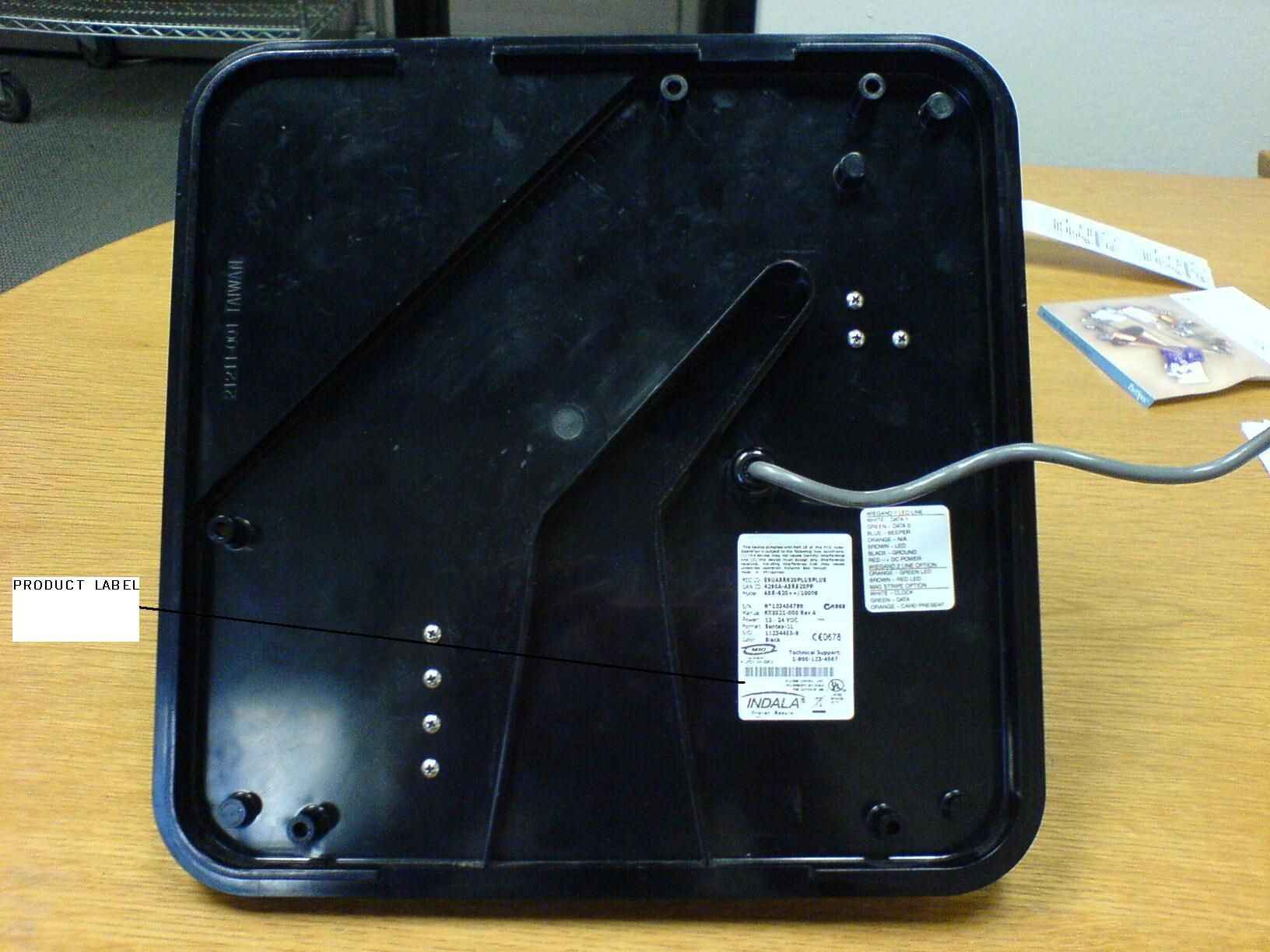
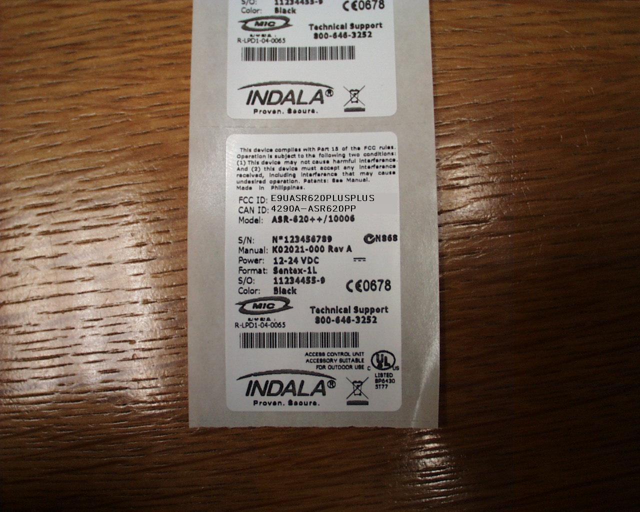
Appendix A Non-Conformities for US Radio Equipment Authorization Non-Conformities FCC ID: E9UASR620PLUSPLUS (Ref # E06-000141- 1) The items listed below represent requests for information following review of this application. Further question may arise pending review of responses to these items. OK # Non-Conformity or Comment Submitted Response Y 1 FCC ID number is too long, please provide FCC ID number in proper format (14 Characters Max).. ID was correct Y 2 Please provide a block diagram including the frequencies of all clocks used in the device. For example, the schematics show an 8MHz clock, but this is not included on the block diagram. Revised Block Diagram submitted Y 3 Although the manual includes 15.105 requirements, it is missing requirements of 15.19. Please provide a label with labeling requirements in accordance with 15.19., “This device complies with Part 15 of the FCC Rules. Operation is subject to the following two conditions: (1) this device may not cause harmful interference, and (2) this device must accept any interference received, including interference that may cause undesired operation..” Exhibit provided Y 4 Please provide documentation indicating ID label placement. Exhibit provided Y 5 Please provide a users manual incorporating the statement required by 15.21. Revised users manual submitted y 6 Please provide demonstration of compliance to 15.31(e) voltage variations. Revised test report provided Y 7 Please justify test distance correction factor used in accordance with 15.31(f) for data presented on pages 7 and 8 of test report. Revised test report submitted y 8 Compliance to 15.209 at the carrier is not clearly documented; test distance correction factor used was unjustified; please provide evidence of compliance at the carrier. Revised test report submitted Y 9 CKC CS ONLY: CKC to perform FCC ID uniqueness check It was done and in file. Non-Conformities FCC ID: E9UASR620PLUSPLUS (Ref # E06-000141- 2) The items listed below represent requests for information following review of this application. Further question may arise pending review of responses to these items. OK # Non-Conformity or Comment Submitted Response y 6 Please provide demonstration of compliance to 15.31(e) voltage variations. A revised test report has been uploaded y 8 Compliance to 15.209 at the carrier is not clearly documented; test distance correction factor used was unjustified; please provide evidence of compliance at the carrier. A revised test report has been uploaded The items indicated above must be submitted before processing can continue on the referenced application. Failure to provide the requested information within 60 days may result in application dismissal pursuant to Section 2.917(c) and forfeiture of the filing fee pursuant to Section 1.1106. ---CKC CS SECTION--- ---Information below this line is for CKC CS Evaluators only--- CKCCS Note: Any corrections or additions to this report can only be made by a further document which meets the requirements of TCB0005 and such a document is to be labeled as a supplement to evaluation report serial number E06-000141.
Cover Letter(s)
Response to E06-000141-2 6. A revised test report has been uploaded. 8. A revised test report has been uploaded.
External Photos
Front Back Top Bottom Left Right
Internal Photos
Internal Overview Main PCB Top Internal Overview Main PCB Top 1 Internal Overview Main PCB Top 2 Main PCB Top Closeup 1 Main PCB Top Closeup 2 Main PCB Top Closeup 3 Main PCB Top Closeup 4 Main PCB Top Closeup 5 Main PCB Top Closeup Antenna Output with Shield Removed Main PCB Top Closeup TX Circuit Underside Main PCB Top Closeup TX Underside Closeup Main PCB Top Closeup TX Underside Closeup with Shield Removed Main PCB Bottom TX PCB Top TX PCB Top with Shield Removed TX PCB Top Closeup 1 TX PCB Top Closeup 2 TX PCB Top Closeup 3 TX PCB Bottom TX PCB Bottom Closeup 1 TX PCB Bottom Closeup 2 TX PCB Bottom Closeup 3 Receiver Coil
Test Report
Page 1 of 28 Report No.: FC06-018A ADDENDUM TO INDALA TEST REPORT FC06-018 FOR THE ASR-620++ LONG RANGE 125KHZ READER FCC PART 15 SUBPART C SECTIONS 15.207 & 15.209 AND RSS-210 COMPLIANCE DATE OF ISSUE: MAY 22, 2006 PREPARED FOR: Indala 6850 B Santa Teresa Blvd. San Jose, CA 95119-1205 PREPARED BY: Mary Ellen Clayton CKC Laboratories, Inc. 5046 Sierra Pines Drive Mariposa, CA 95338 P.O. No.: 14003207 W.O. No.: 84492 Date of test: January 31 - February 1, 2006 Report No.: FC06-018A This report contains a total of 28 pages and may be reproduced in full only. Partial reproduction may only be done with the written consent of CKC Laboratories, Inc. The results in this report apply only to the items tested, as identified herein. Page 2 of 28 Report No.: FC06-018A TABLE OF CONTENTS Administrative Information .............................................................................................3 FCC to Canada Standard Correlation Matrix...................................................................4 Conditions for Compliance ..............................................................................................4 Approvals .........................................................................................................................4 FCC 15.31(e) Voltage Variations ....................................................................................5 FCC 15.31(m) Number Of Channels ...............................................................................5 FCC 15.33(a) Frequency Ranges Tested .........................................................................5 FCC 15.35 Analyzer Bandwidth Settings ........................................................................5 FCC 15.203 Antenna Requirements ................................................................................5 EUT Operating Frequency ...............................................................................................5 Temperature And Humidity During Testing....................................................................5 Equipment Under Test (EUT) Description ......................................................................6 Equipment Under Test .....................................................................................................6 Peripheral Devices ...........................................................................................................6 Report of Measurements ..................................................................................................7 Table 1: FCC 15.207 Six Highest Conducted Emission Levels ..........................7 Table 2: FCC 15.209 Fundamental Emission Levels ..........................................8 Table 3: FCC 15.209 Six Highest Radiated Emission Levels: 9 kHz - 30 MHz .9 Table 4: FCC 15.209 Six Highest Radiated Emission Levels: 30-1000 MHz.....10 Occupied Bandwidth............................................................................................11 EUT Setup........................................................................................................................12 Correction Factors............................................................................................................12 Table A: Sample Calculations .............................................................................12 Test Instrumentation and Analyzer Settings ....................................................................13 Spectrum Analyzer Detector Functions ...............................................................13 Peak..........................................................................................................13 Quasi-Peak ...............................................................................................13 Average ....................................................................................................13 EUT Testing.....................................................................................................................14 Mains Conducted Emissions................................................................................14 Radiated Emissions ..............................................................................................14 Appendix A: Test Setup Photographs..............................................................................15 Photograph Showing Mains Conducted Emissions .............................................16 Photograph Showing Mains Conducted Emissions .............................................17 Photograph Showing Radiated Emissions ...........................................................18 Photograph Showing Fundamental Emissions.....................................................19 Appendix B: Test Equipment List ...................................................................................20 Appendix C: Measurement Data Sheets ..........................................................................21 Page 3 of 28 Report No.: FC06-018A ADMINISTRATIVE INFORMATION DATE OF TEST: January 31 - February 1, 2006 DATE OF RECEIPT: January 31, 2006 MANUFACTURER: Indala 6850 B Santa Teresa Blvd. San Jose, CA 95119-1205 REPRESENTATIVE: Steve Rose TEST LOCATION: CKC Laboratories, Inc. 5046 Sierra Pines Drive Mariposa, CA 95338 TEST METHOD: ANSI C63.4 (2003), RSS-210 and RSS-GEN PURPOSE OF TEST: To demonstrate the compliance of the ASR-620++ Long Range 125kHz Reader with the requirements for FCC Part 15 Subpart C Sections 15.207 & 15.209 and RSS-210 devices. Addendum A is to revise the fundamental and 9kHz-30MHz data sheets and tables and add voltage variation data with no new testing. Page 4 of 28 Report No.: FC06-018A FCC TO CANADA STANDARD CORRELATION MATRIX Canadian Standard Canadian Section FCC Standard FCC Section Test Description RSS GEN7.1.447CFR15.203Antenna Connector Requirements RSS GEN7.2.147CFR15.35(c)Pulsed Operation RSS GEN7.2.247CFR15.207AC Mains Conducted Emissions Requireme…
Text truncated - open the document above for the full version.
Test Setup Photos
PHOTOGRAPH SHOWING MAINS CONDUCTED EMISSIONS Mains Conducted Emissions - Front View PHOTOGRAPH SHOWING MAINS CONDUCTED EMISSIONS Mains Conducted Emissions - Side View PHOTOGRAPH SHOWING RADIATED EMISSIONS Radiated Emissions PHOTOGRAPH SHOWING FUNDAMENTAL EMISSIONS Fundamental Emissions
Contact Information
Applicant
Frank de Vall(Sr. Manager - Compliance Engineering)
Technical Contact
CKC Laboratories, Inc.Mary Ellen Clayton
[email protected]800-500-4362
5046 Sierra Pines Drive · Mariposa, California · United States
Test Firm
CKC Laboratories, Inc.Steve Behm
Technical Specifications
| # | Rule Parts | Frequency Range | Power Output |
|---|---|---|---|
| 1 | 15C | 0.125 MHz - 0.125 MHz | - |
Other Applications from HID Global Corporation
E9UX200
May 30, 2005X200 Series
Equipment Class
DXX - Part 15 Low Power Communication Device Transmitter
E9UCX-8525
Jun 04, 2003Proximity Reader, CX-8525
Equipment Class
DXX - Part 15 Low Power Communication Device Transmitter
E9UARK501
Sep 15, 2002Flexpass Keypad Reader
Equipment Class
DXX - Part 15 Low Power Communication Device Transmitter
E9UOFR100
Aug 19, 2001PROXIMITY READER
Equipment Class
DCD - Part 15 Low Power Transmitter Below 1705 kHz
E9U05866001T1
Jun 11, 2001RFID Reader/Writer
Equipment Class
DCD - Part 15 Low Power Transmitter Below 1705 kHz