E9UCX-8525Proximity Reader, CX-8525
HID Global Corporation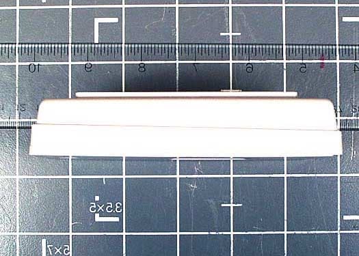
Click to zoom
Application Details
- Equipment Class
- DXX - Part 15 Low Power Communication Device Transmitter
- Date of Grant
- Jun 04, 2003
- Application Purpose
- Original Equipment
- Date of Application
- Jun 04, 2003
- Equipment Note
- Proximity Reader, CX-8525
- Frequency Range
- 0.13000000 - 0.13000000
- Company
- HID Global Corporation
- Country
- United States
Documents & Files
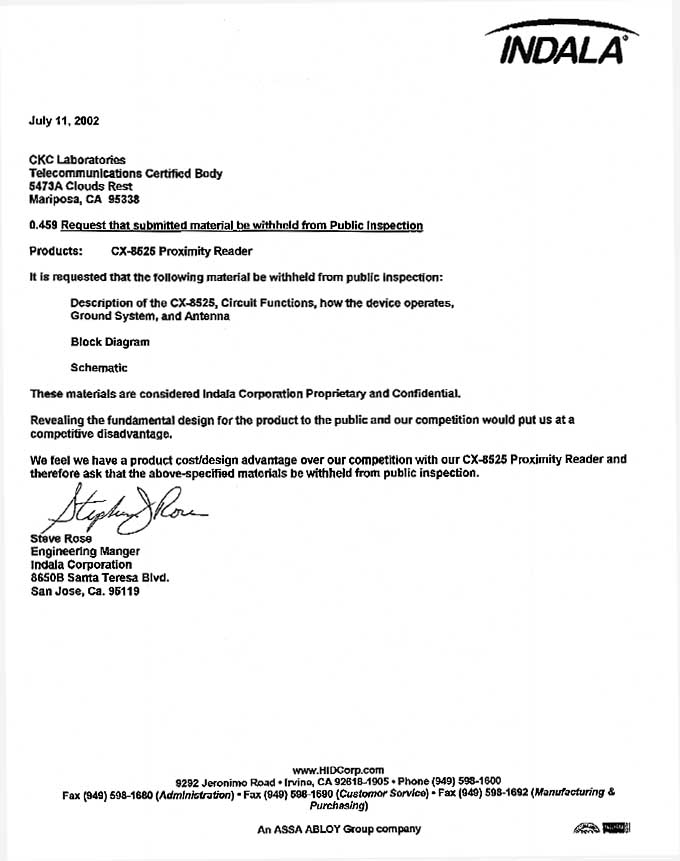
Document Text
Text extracted from the exhibit documents filed with the FCC. Open a document above to read the original.
Users Manual
06/05/03 330413.DOC REV. A I CX-8525 Installation and Operation Manual 06/05/03 330413.DOC REV. A II FCC Compliance: This device complies with part 15 of the FCC Rules. Operation is subject to the following two conditions: (1) This device may not cause harmful interference, and (2) this device must accept any interference received, including interference that may cause undesired operation. Changes or modifications not expressly approved by the party responsible for compliance could void the user’s authority to operate the equipment. Canadian Compliance: Operation is subject to the following two conditions: (1) this device may not cause interference, and (2) this device must accept any interference, including interference that may cause undesired operation of the device. UL: The reader is intended to be powered from a limited power source output of a previously certified power supply. CE Compliance: Hereby, Indala, declares that this proximity reader is in compliance with essential requirements and other relevant provisions of Directive 1999/5/EC. Notice: The CX-8525 reader requires the use of linear, series pass, regulated power supplies. Use of other types of power supply can result in reduced read range. The use of switching power supplies is not recommended. Do not use the reader's power supply for other equipment, particularly when operating switched inductive loads such as motor control relays and solenoids (i.e., magnetic locks, latch or strike). Doing so will affect the reader operation. Use a separate dedicated power supply for Indala proximity readers. Because this technology is based on radio frequency and because nearby environmental sources of electrical interference may affect the performance of the reader, below is a list of precautions that should be considered when installing or wiring the reader: • Metal affects radio signals. Do not cover the face of the reader with metal of any kind. • Reduce or eliminate unwanted signals from external sources. • Do not place the reader wiring bundled in conduit with AC power cables, lock power, or signal wiring. Where possible. • Maintain all reader wiring a minimum distance of 12" (30 cm) away from other wiring such as AC power, computer data wiring, telephone wiring, or wiring to electric locking devices, etc. • Avoid installing the reader in areas where sources of broad spectrum EMI noise may be present. Examples of EMI broad spectrum noise producers are motors, pumps, generators, AC-DC converters, uninterruptible power supplies, AC switching relays, light dimmers, computer monitors, and CRTs • Do not install the reader within 3.5' (1.1 m) of computer 06/05/03 330413.DOC REV. A III Table of Contents 1.0 Product Specification.................................................................................................................................. 1 2.0 Introduction................................................................................................................................................ 2 2.1 Features.................................................................................................................................................................2 2.2 Theory of Operation.................................................................................................................................................2 2.3 Unpacking and Identifying Supplied Parts..................................................................................................................3 3.0 Installation................................................................................................................................................. 3 3.1 Mechanical Installation.............................................................................................................................................3 3.1.1 Gang Box Mounting (Preferred mounting Configuration).......................................................................................3 3.1.2 Wall Mounting..................................................................................................................................................3 3.2 Electrical Installation...........................................................................................................................................3 3.2.1 Reader Switch Settings....................................................................................................................................3 3.2.2 Reader to Host Interface Cable Types and Lengths.............................................................................................4 3.2.3 Earth Grounding...............................................................................................................................................5 3.2.4 Reader to Host Interface Wiring.........................................................................................................................5 4.0 Operation................................................................................................................................................... 5 4.1 Presenting the Credential.........................................................................................................................................5 4.2 Data Output............................................................................................................................................................6 5.0 Controls and Indicators...............................................................................................................................6 5.1 LED and Beeper Control..........................................................................................................................................6 6.0 Troubleshooting.......................................................................................................................................... 7 7.0 Copyrights, Patents, and Tr…
Text truncated - open the document above for the full version.
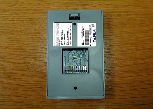
External Photos
Front Back Top Bottom Left Right
Internal Photos
Antenna Inside Back Cover PCB Front PCB Back
Test Report
Page 1 of 28 Report No.: FC03-031 INDALA CORPORATION TEST REPORT FOR THE PROXIMITY READER, CX-8525 FCC PART 15 SUBPART C SECTIONS 15.207 & 15.209 COMPLIANCE DATE OF ISSUE: MAY 9, 2003 PREPARED FOR: Indala Corporation 6850 B Santa Teresa Blvd. San Jose, CA 95119-1295 PREPARED BY: Mary Ellen Clayton CKC Laboratories, Inc. 5473A Clouds Rest Mariposa, CA 95338 P.O. No.: 10001163 W.O. No.: 80545 Date of test: May 2-8, 2003 Report No.: FC03-031 This report contains a total of 28 pages and may be reproduced in full only. Partial reproduction may only be done with the written consent of CKC Laboratories, Inc. The results in this report apply only to the items tested, as identified herein. Page 2 of 28 Report No.: FC03-031 TABLE OF CONTENTS Administrative Information .............................................................................................3 Summary of Results .........................................................................................................4 Conditions for Compliance ..............................................................................................4 Approvals .........................................................................................................................4 FCC 15.31(e) Voltage Variation......................................................................................5 FCC 15.31(m) Number Of Channels ...............................................................................5 FCC 15.33(a) Frequency Ranges Tested .........................................................................5 FCC 15.35 Analyzer Bandwidth Settings ........................................................................5 FCC 15.203 Antenna Requirements ................................................................................5 FCC 15.205 Restricted Bands..........................................................................................5 Eut Operating Frequency .................................................................................................5 Temperature And Humidity During Testing....................................................................5 Equipment Under Test (EUT) Description ......................................................................6 Equipment Under Test .....................................................................................................6 Peripheral Devices ...........................................................................................................6 Report of Measurements ..................................................................................................7 Table 1: FCC 15.207 Six Highest Conducted Emission Levels ..........................7 Table 2: FCC 15.209 Fundamental Emission Levels ..........................................8 Table 3: FCC 15.209 Six Highest Radiated Emission Levels .............................9 FCC 15.215 Bandedge Compliance.....................................................................10 RSS 210 Section 5.9.1 Bandwidth Plot ...............................................................11 Measurement Uncertainty ................................................................................................12 EUT Setup........................................................................................................................12 Correction Factors............................................................................................................12 Table A: Sample Calculations .............................................................................12 Test Instrumentation and Analyzer Settings ....................................................................13 Spectrum Analyzer Detector Functions ...............................................................13 Peak..........................................................................................................13 Quasi-Peak ...............................................................................................13 Average ....................................................................................................13 EUT Testing.....................................................................................................................14 Mains Conducted Emissions................................................................................14 Radiated Emissions ..............................................................................................14 Appendix A: Test Setup Photographs..............................................................................15 Photograph Showing Mains Conducted Emissions .............................................16 Photograph Showing Mains Conducted Emissions .............................................17 Photograph Showing Radiated Emissions ...........................................................18 Photograph Showing Radiated Emissions ...........................................................19 Appendix B: Test Equipment List ...................................................................................20 Appendix C: Measurement Data Sheets ..........................................................................21 Page 3 of 28 Report No.: FC03-031 ADMINISTRATIVE INFORMATION DATE OF TEST: May 2-8, 2003 DATE OF RECEIPT: May 2, 2003 PURPOSE OF TEST: To demonstrate the compliance of the Proximity Reader, CX-8525 with the requirements for FCC Part 15 Subpart C Sections 15.207 & 15.209 devices. TEST METHOD: ANSI C63.4 (1992) MANUFACTURER: Indala Corporation 6850 B Santa Teresa Blvd. San Jose, CA 95119-1295 REPRESENTATIVE: Steve Rose TEST LOCATION: CKC Laboratories, Inc. 5473A Clouds Rest Mariposa, CA 95338 Page 4 of 28 Report No.: FC03-031 SUMMARY OF RESULTS As received, the Indala Corporation Proximity Reader, CX-8525 was found to be fully compliant with the following standards and specifications: United States ! FCC 15.209 ! FCC 15.205 ! FCC 15.207 ! N…
Text truncated - open the document above for the full version.
Test Setup Photos
PHOTOGRAPH SHOWING MAINS CONDUCTED EMISSIONS Mains Conducted Emissions – Front View PHOTOGRAPH SHOWING MAINS CONDUCTED EMISSIONS Mains Conducted Emissions – Side View PHOTOGRAPH SHOWING RADIATED EMISSIONS Radiated Emissions – Front View PHOTOGRAPH SHOWING RADIATED EMISSIONS Radiated Emissions – Back View
Contact Information
Applicant
Frank de Vall(Sr. Manager - Compliance Engineering)
Technical Contact
CKC Laboratories, IncMary Ellen Clayton
[email protected]209-966-5240
5473A Clouds Rest · Mariposa, California · United States
Non-Technical Contact
CKC Laboratories, IncMary Ellen Clayton
[email protected]209-966-5240
Test Firm
CKC Laboratories, Inc.Steve Behm
Technical Specifications
| # | Rule Parts | Frequency Range | Power Output |
|---|---|---|---|
| 1 | 15C | 0.13 MHz - 0.13 MHz | - |
Other Applications from HID Global Corporation
E9UASR620PLUSPLUS
May 30, 2006ASR-620++ Long Range Reader
Equipment Class
DCD - Part 15 Low Power Transmitter Below 1705 kHz
E9UX200
May 30, 2005X200 Series
Equipment Class
DXX - Part 15 Low Power Communication Device Transmitter
E9UARK501
Sep 15, 2002Flexpass Keypad Reader
Equipment Class
DXX - Part 15 Low Power Communication Device Transmitter
E9UOFR100
Aug 19, 2001PROXIMITY READER
Equipment Class
DCD - Part 15 Low Power Transmitter Below 1705 kHz
E9U05866001T1
Jun 11, 2001RFID Reader/Writer
Equipment Class
DCD - Part 15 Low Power Transmitter Below 1705 kHz