EHC20603Telemetry TX
Medical Data Electronics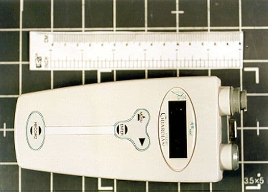
Click to zoom
Application Details
- Equipment Class
- DXX - Part 15 Low Power Communication Device Transmitter
- Date of Grant
- May 25, 2000
- Application Purpose
- Original Equipment
- Date of Application
- Apr 13, 2000
- Equipment Note
- Telemetry TX
- Frequency Range
- 608.00000000 - 614.00000000
- Company
- Medical Data Electronics
- Country
- United States
Documents & Files
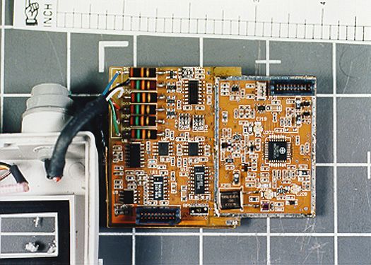
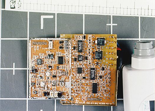
Document Text
Text extracted from the exhibit documents filed with the FCC. Open a document above to read the original.
Users Manual
ESCORT Guardian™ Telemetry Transmitter Operators Manual P/N: E9030-76 Stock # 403592-0000 Rev A Federal law restricts this device to sale by or on the order of a physician. Medical Data Electronics • 12720 Wentworth Street • Arleta. California 91331-4329 (800) 237-5243 • (818) 768-6411 • FAX (818) 768-0759 403592-0000 Rev B ii PREFACE The Escort Guardian™ telemetry transmitter is intended only as an adjunct to patient assessment. It cannot replace skilled nursing care and proper surveillance. Be sure to carefully read this operator’s manual, all directions for use of the Guardian, ESCORT monitors and monitor accessories, and all precautionary information before attempting clinical use of the Guardian. Always keep high-risk patients under close surveillance. The information in this document is subject to change without notice. WARRANTY The ESCORT Guardian is warranted against defects in materials and workmanship for twelve (12) months from the date of shipment to the original purchaser. Accessories such as batteries, cables, cuffs, and sensors are warranted for ninety (90) days from date of shipment. Warranty is valid only to the original buyer. Defective equipment should be returned freight prepaid to Medical Data Electronics. Equipment returned with defective parts and assemblies will be either repaired or replaced. This warranty is not applicable if repair has been attempted, if the instrument has been damaged due to 403592-0000 Rev B iii operation outside the environmental and power specifications for the product, or due to improper handling or use. If any fault develops, notify MDE Technical Service giving full details of the difficulty, and include the model and serial number of the device. Upon receipt of the shipping instructions, forward the device prepaid and repairs will be made at the factory. The foregoing warranty is in lieu of all other warranties expressed or implied, including but not limited to any implied warranty or merchantability, fitness or adequacy for any particular purpose or use. Medical Data Electronics shall not be liable for any incidental or consequential damages . TECHNICAL SERVICE If you experience any problems with this product or would like more information about related equipment, please call one of the telephone numbers listed below. Medical Data Electronics is dedicated to providing accurate and timely responses to all of our customers’ requests. 403592-0000 Rev B iv Toll Free Technical Service: (800) 237-5243 Technical Service(818) 768-6411 MDE FAX Line(818) 768-0759 Written requests for information should be addressed to: Medical Data Electronics, Inc. 12720 Wentworth Street Arleta, CA 91331-4309 SAFETY CONSIDERATIONS The ESCORT Guardian telemetry transmitter is intended for use by healthcare practitioners only. Observe these safety precautions, as well as those that appear within the text of the manual. 403592-0000 Rev B v Warning: The connector on the Guardian unit labeled “AUX” must only be connected to IEC601- or UL2601-approved equipment. In addition, the Guardian is designed for use in its clear protective pouch. Caution: Take care to transport and store the Guardian in accordance with the ranges specified in the following guidelines for environmental conditions. Temperature -40 ° C to 70° C Relative Humidity 10% to 100 % Atmospheric Pressure 500 hPa to 1060 hPa Note: The Guardian is safe to use during defibrillation. Note: This device complies with FCC rules Part 15. Operation is subject to the following conditions (1) this device must not cause harmful interference, and (2 this device must accept any interference that may be received, including interference that may cause undesired operation. 403592-0000 Rev B vi Note: The 9v batteries that power the Guardian are consumable components and must be replaced regularly to ensure proper operation of the unit. Take care to dispose of used batteries properly, according to your local regulations . SYMBOLS The following are cautionary symbols that appear on the Guardian unit. Familiarize yourself with these symbols before using the Guardian. Attention: Consult accompanying documents. 403592-0000 Rev B vii TABLE OF CONTENTS Preface..................................................................................................................................................... ii Warranty.................................................................................................................................................. ii Technical Service ................................................................................................................................... iii Safety Considerations............................................................................................................................. iv Symbols .................................................................................................................................................. vi About This Manual.................................................................................................................................. x About the ESCORT Guardian™ ..............................................................................................................1-1 Before Using The Guardian .................................................................................................................1-1 Interacting With The Guardian Telemetry Transmitter .......................................................................1-2 Using The Key Pad Lock Out Feature .................................................................................................1-4 Unlocking The Keypad ........................................................................................................................1-4 Powering Up The Guardian..................................................................................................................1-5 Powering Off The Guardian ......................…
Text truncated - open the document above for the full version.
Users Manual
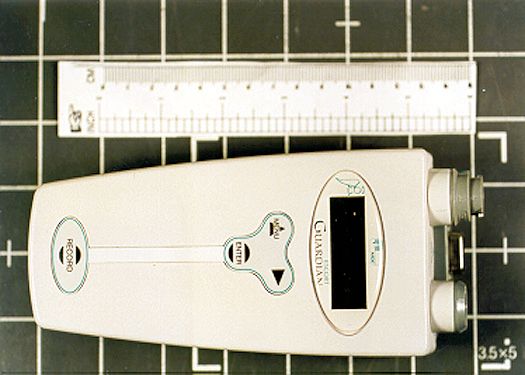
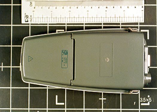
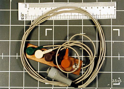
403592-0000 1- Rev A 1 Part One: About the ESCORT Guardian™ The ESCORT Guardian™ telemetry transmitter is the next generation of wireless point-of-care multi- parameter patient monitoring. The Guardian is capable of providing you with continuous measurement of dual-lead ECG and the addition of the SpO 2 module supports continuous pulse oximetry measurement, either continuously or at intervals. The Guardian unit is worn by the patient, providing free ambulation for your patients. It monitors supported vital signs and transmits that information to ESCORT II series bedside monitors and to the Vision Central Station. Before Using the Guardian Make sure to use the Guardian only when it has been inserted into its clear vinyl pouch. This disposable pouch helps protect the unit from dirt and moisture while at the same time allowing access to the display 403592-0000 1- Rev A 2 and the keys. Place the unit in the pouch (part number 403539-0000) and thread the patient belt (part number 403538-0000) through the loops on the back of the pouch. The belt can then be positioned on the patient however is most practical and comfortable. Both the pouch and the belt are designed to be disposable. Contact MDE to order more, as necessary. Interacting with the Guardian Telemetry Transmitter The ESCORT Guardian™ telemetry transmitter is designed with an easy-to-use interface. There are four keys on the front of the transmitter that you will use to make selections from a series of sequential menus to interact with the Guardian. You indicate which menu options you want to select by touching buttons on the Guardian’s keypad. 403592-0000 1- Rev A 3 To Do This...Touch This... To turn on the LCD Menu From within the menu structure, to back up to the previous menu Menu To display the main menu Menu (Press and Hold for one second) To move through menu selections, touch the right arrow until the desired option is flashing. Arrow To select the currently highlighted menu option. Enter To initiate a remote recording Record 403592-0000 1- Rev A 4 A selected option flashes; an option that is currently in effect is marked with an asterisk (*). In this guide a direction to “select” an options means to highlight it with the arrow key and press Enter. Using the Key Pad Lock Out Feature In order to prevent patients from changing transmitter settings, the Guardian keypad is equipped with a locking feature. When the keypad is locked, all keypad functions are disabled except the Remote Record function which operates normally. The keypad will lock each time the LCD is powered on. If the LCD is configured for continuous operation, the keypad will lock after 90 seconds of inactivity. The keypad will also lock any time you enter the Configuration Setup menu. When the keypad is locked, the unit will display a lock icon in the upper left corner. No icon is displayed when the keypad is unlocked. 403592-0000 1- Rev A 5 Unlocking the Keypad To unlock the keypad any time it is locked, press and hold the right arrow button for 3 seconds. The lock icon will disappear and the keypad will function normally. Keep in mind that any time you select Conf functions, the keypad will lock and you will need to unlock it by holding down the arrow key for 3 seconds before you can proceed. Powering Up the Guardian 1. Insert a 9 volt (alkaline or lithium) battery into one or both of the battery chambers. Make sure the negative pole (-) is facing up. The negative pole is the larger of the two poles. 2. Once the battery is inserted, the Guardian transmitter will display its power-up menu, which will display for approximately 30 seconds, or until you press a button to initiate a function. 3. The power-up menu will display the currently set transmitter channel and the software version contained in the transmitter. Figure 1-2 depicts what you will see. 403592-0000 1- Rev A 6 Figure 1-1 Guardian Power Up Menu Note: If the channel field contains “ ???” this means that configuration information has been lost and you must reprogram a channel. Refer to “Configuring the Guardian” in Part 5 of this guide for information on how to reprogram the transmitter’s channel. Powering off the Guardian The Guardian’s power remains on as long as a battery is in place in the battery chamber. To power-off the Guardian for long-term storage or non-use, remove the battery. Refer to Part 5 of this guide for instructions on how to use the Guardian’s power stand-by mode. CHANNL=G12 V01000000 2 403592-0000 1- Rev A 7 Additional Guardian Accessories A range of accessories are available to support your use of the Guardian unit. Refer to these part numbers when ordering: DescriptionPart Number Sp O 2 Ext. Cable 3 Ft.3350200-0081A Sp O 2 Cable Adult Univ. 3 Ft350200-0082A Sp O 2 Cable Peds. 2 Ft. Disp. 10 Pack350200-0083A Sp O 2 Cable Adult 2 Ft. Disp. 10 Pack350200-0078A Sp O 2 Cable Adult 3 Ft.350200-0077A Sensor, SpO 2 Ped. Finger Clip, Non-invasive350200-0079A 403592-0000 1- Rev A 8 DescriptionPart Number 9v Alkaline Battery384000-0153A 9v Lithium Battery384000-0229A Clear vinyl pouch403539-0000 Patient belt403538-0000 Operator’s Guide43592-0000 Caring for the Guardian Unit Although use of the Guardian’s accompanying vinyl pouch will help keep it clean, periodically, you should clean the unit. Follow these guidelines: 403592-0000 1- Rev A 9 • Use only a lint free, nonabrasive cloth which has been slightly dampened with a mild detergent. A glass cleaner or a non-alcoholic based solvent is recommended. • Avoid harsh cleaning solutions such as isopropyl alcohol or other solvents that might harm plastic surfaces. • Do not immerse the unit or any of its components in liquid. • Do not spray liquids directly onto the Guardian. • Do not allow liquids to penetrate the connectors or the Guardian’s case. 403592-0000 1- Rev A 10
Users Manual
403592-0000 2- Rev A 1 Part Two: ECG Monitoring The ECG monitoring feature supports the following functions: • Verifying ECG lead • Changing the default lead • Turning off ECG monitoring Verifying Leads You can use the LD CHK menu to verify at the point of care that all electrodes are connected to the patient. You can also assess the quality of the electrode connection and that an ECG connection is present. 403592-0000 2- Rev A 2 1. From the Main menu, select ECG . 2. The ECG menu will display as depicted in Figure 2-1. Figure 2-1 . ECG Menu 3. Select LD CHK. The Lead Check menu will appear as depicted in Figure 2-2. ECG Menu LD CHK MORE LA RA LL V: RL: SIG 403592-0000 2- Rev A 3 Figure 2-2 . L ead Check Menu This display screen contains a bar graph for each lead wire. If no bar is displayed, no signal is being received. A full bar indicates a full signal. The SIG display indicates the ECG signal amplitude. SIG levels above ½ bar indicate adequate signal levels to ensure that the receiver recognizes the ECG. Changing the Default ECG Lead If you are using a 3-lead ECG cable, you can temporarily change the default lead. If the transmitter is connected to a patient with only RA, LA, and LL electrodes, only one lead can be derived at a time. You must select which lead (I or II) will be sent to the receiver. To do this: 403592-0000 2- Rev A 4 1. From the Main menu choose ECG . 2. From the ECG menu, choose More . The ECG More menu will appear as depicted in Figure 2-3. Figure 2-3. ECG More Menu Select 3 LD Sel to display the 3LD SEL menu. It is depicted in Figure 2-4. ECG More 3 LD SEL Off 3LD Select I II * 403592-0000 2- Rev A 5 Figure 2-4. 3LD Sel Menu Select the lead you want to use. Press Enter. Once you make a selection, you will return to the ECG More menu. Turning Off ECG Monitoring 1. From the Main menu select ECG . 2. From the ECG Menu, select More . 3. From ECG More menu, select OFF . The ECG off menu will appear as depicted in Figure 2-5, requiring you to confirm your selection. ECG OFF Yes No 403592-0000 2- Rev A 6 Figure 2-5. ECG Off Menu Yes will be flashing as the currently selected default. To turn off ECG monitoring, press Enter . ECG monitoring will stop and the display will return to the Main menu. Note: ECG monitoring cannot be turned off if a valid ECG signal (at least 3 leads) is detected. To continue ECG monitoring select No and press Enter . ECG monitoring will continue and the ECG menu will be displayed.
Users Manual
403592-0000 3- Rev A 1 Part Three: SpO 2 Monitoring Feature If your unit is equipped with the optional SpO 2 feature, you can: • View real-time O 2 sat and pulse rate values • Customize SpO 2 settings • Specify an SpO 2 reading interval • Turn SpO 2 off • Select an SpO 2 mode To determine whether your unit has these features available, check the Main menu. If the SpO2 option is available, “SpO 2 ” will appear on the main menu If you do not have the SpO2 option, all SpO2 menus will be blank. 403592-0000 3- Rev A 2 Viewing O2 Sat and Pulse Rate 1. From the Main menu, select O 2 . The SpO 2 menu will display as depicted in Figure 3-1. Figure 3-1. SpO 2 Menu Note: Selecting O 2 or plugging an SpO 2 sensor into the unit will turn this function on if it was previously turned off in deep configuration or with the interval setting. . 2. Select O2 Val to view real time O 2 sat and pulse rate values, along with a pleth bar that indicates signal amplitude. Figure 3-2 represents an example of this display. SpO2 Menu O2 VAL setup 403592-0000 3- Rev A 3 Figure 3-2. O 2 Val Display If the values for O2 % and O2 PR are flashing, the SpO2 mode is set to something other than continuous. Refer to “Setting SpO2 Interval” for more information. Customizing SpO 2 Settings You can specify the reading interval, turn the O 2 function off, and select a filter mode for O2 data. Setting SpO 2 Reading Interval To select the SpO2 reading interval: 1. From the Main menu select O 2 . O2 SAT: 100 % O2 PR: 70 403592-0000 3- Rev A 4 2. From the SpO2 menu, select Setup. The SpO 2 Setup menu will display as depicted in Figure 3-3. Figure 3-3. SpO2 Setup Menu 3. Select Intervl to display the SpO2 Frequency Settings Menu as depicted in Figure 3-4. Figure 3-4. SpO 2 Frequency Settings Use the Arrow button to cycle through the options on this menu, until the one you want flashes. Press Enter to complete your selection. The following options are available: SpO2 Setup Intervl Mode O2 INT/MIN Cont * 1 2 off 403592-0000 3- Rev A 5 ContinuousO 2 Sat values and waveform are continuously sent to the central and the display is updated accordingly. The O 2 display will not flash if Mode is set to Continuous. 1 minute or 2 minuteIn either the 1- or 2-minute interval mode, the SpO 2 function will be turned on for approximately 30 seconds while it acquires and displays readings for O 2 Sat % and Pulse rate. Then it will shut off. No waveform will be sent if Interval is set to 1 or 2 minute mode. OffIf you select Off, another menu will appear as depicted in Figure 3-5, requiring you to confirm your selection. “ Yes” will flash as the currently selected default. To turn off the O 2 parameter, press Enter . The display will return to the Main menu. To leave O2 monitoring on, select No . The SpO 2 Interval menu will redisplay. 403592-0000 3- Rev A 6 Figure 3-5. SpO 2 Off Confirmation Menu Selecting a Filter Mode You can select one of 2 filter modes for Sp0 2 monitoring. Use “Normal” when there is minimal patient movement and “slow” if you expect more movement. To change filter mode: 1. From the Main menu select O 2 . 2. From the SpO 2 menu, select Setup. 3. From the Setup menu select Mode to display the SpO 2 Mode menu as depicted in Figure 3-6. O2 off? Yes no 403592-0000 3- Rev A 7 Figure 3-6 . SpO 2 Mode Menu Select the appropriate mode and press Enter . Once you have made your selection, the display will return to the SpO 2 Setup menu. SpO2 Mode Normal * Slow 403592-0000 3- Rev A 8
Users Manual
403592-0000 4- Rev A 1 Part Four Entering Data Manually The ESCORT Guardian telemetry transmitter supports the manual entry of certain types of data. You can manually enter : • temperature • respiration • non-invasive blood pressure (NIBP) into the Guardian transmitter for subsequent transmission to the central station or bedside. Entering Manual Temperature Measurements To enter temperature manually, do the following: 403592-0000 4- Rev A 2 1. From the Main menu select More . 2. Select Manual . The Manual Entry menu will display as depicted in Figure 4-1. Figure 4-1. Manual Entry Menu 3. From Manual Entry, select TMP . The Temp Entry menu will display as depicted in Figure 4-2. Figure 4-2. Temp Entry Menu MANUAL ENTRY TMP RSP NIBP TEMP 98.6° ρ ο SAVE 403592-0000 4- Rev A 3 4. The display will default to the most recent previously entered value. If no temperature has been previously entered for the patient, the display will default to 98.6 degrees Fahrenheit (or 37.0 degrees centigrade, depending on how temperature is set up to display). Refer to “Configuring the Guardian” for information on changing the temperature display mode. 5. Highlight either the up or down arrow on the display to increase or decrease the displayed temperature. Press and release Enter to change the temperature by .1 (one-tenth) degree. Press and Hold Enter key to quickly change the temperature 1 (one) degree at a time. 6. Once you have entered the appropriate value, select Save to transmit the temperature value to the receiver. 7. The display will revert to the Manual Entry menu, and the next option for manual entry will be flashing. Press Enter to select it and continue entering data. If you do not want to make any more manual entries, press Menu to return to the Main menu. 403592-0000 4- Rev A 4 Entering Manual Respiration Measurements To enter respiration manually, do the following: 1. From the Main menu select More. 2. Select Manual Entry. Refer to Figure 4-1 for an example of the Manual Entry menu. 3. From Manual Entry, select RSP . The RSP Menu will display as depicted in Figure 4-3. Figure 4-3. RSP Menu Note: You may not need to progress through all menu selections. To minimize key presses, after each manual entry is saved in the transmitter, the menu display reverts to the Manual menu with the next manual enter choice flashing. For example, after RSP 10/min ρ ο SAVE 403592-0000 4- Rev A 5 entering TMP manually, RSP will be flashing. To accept this choice, press Enter. Otherwise press Menu to exit Manual Entry. 4. The RSP display will default to the most recent previously entered value. If no respiration value has been previously entered for the patient, the unit will display the default value of 10. 5. Highlight either the up or down arrow on the display to increase or decrease the displayed respiration. Press and release the Enter key to change the respiration value by 1. Press and hold the Enter key to quickly change the respiration value by 10 points at a time. 6. Once you have entered the appropriate value, select Save to transmit the respiration value to the receiver. 7. The display will revert to the Manual Entry menu, and the next option for manual entry will be flashing. Press Enter to select it and continue entering data. If you do not want to make any more manual entries, press Menu to return to the Main menu. 403592-0000 4- Rev A 6 Entering Manual NIBP Measurements To enter non-invasive blood pressure manually, do the following: 1. From the Main menu select More. 2. Select Manual Entry. Refer to Figure 4-1 for an example of the Manual Entry menu. 3. From Manual Entry, select NIBP . The NIBP Menu will be displayed as depicted in Figure 4-4. Note: You may not need to progress through all menu selections. To minimize key presses, after each manual entry is saved in the transmitter, the menu display reverts to the Manual menu with the next manual enter choice flashing. For example, after entering TMP manually, RSP will be flashing. To accept this choice, press Enter. Otherwise press Menu to exit Manual Entry. 403592-0000 4- Rev A 7 Figure 4-4. NIBP Menu 4. The display will default to the most recent previously entered blood pressure. The Systolic value will be flashing. If no value has been previously entered for the patient, the unit will display a default systolic pressure of 100. 5. Highlight either the up or down arrow on the display to increase or decrease the displayed pressure. Press and release the Enter key to change the pressure value by 1. Press and hold the Enter key to change the pressure by 10. NIBP 100/ 70 ρ ο DIA SAVE 403592-0000 4- Rev A 8 6. To enter diastolic pressure, select DIA. The Diastolic pressure will flash, and will default to the most previously entered Diastolic pressure. If no value has been previously entered for the patient, the unit will display a default diastolic pressure of 70. 7. Highlight either the up or down arrow on the display to increase or decrease the displayed pressure. Press and release the Enter key to change the pressure value by 1. Press and hold the Enter key to quickly change the pressure 10 points at a time. 8. Once you have entered the appropriate blood pressure values, select Save to transmit the respiration value to the central station. 9. The display will revert to the Manual Entry menu, and the next option for manual entry will be flashing. Press Enter to select it and continue entering data. If you do not want to make any more manual entries, press Menu to return to the Main menu.
Users Manual
04/14/00 A - 403592-0000 1 Appendix A: Troubleshooting From time to time you may experience difficulties with your ESCORT Guardian. In many cases the information you need will be here in this chapter. Use the information to help you determine if a customer service call is necessary. If the Problem Is...Try This... Keypad doesn’t functionCheck for the Lock icon on the display. The keypad lockout engages on power up and after 90 seconds of inactivity. Press and hold the arrow key to unlock the keypad. Record FailsBe sure to hold the Record key longer than one second. 04/14/00 A - 403592-0000 2 If the Problem Is...Try This... Record FailsMake sure that Record is not turned off at the Vision. Nothing displays on screenMake sure there are batteries in the battery compartment and that they are not dead. Telemetry standby can’t be activatedStandby cannot be activated if the unit detects an active ECG signal. Disconnect the ECG lead from the patient. Too much noise or artifact on the displayCheck skin prep, check electrodes. Placement may be causing motion pick-up. Signal lossElectrode has been lost or disconnected. Can’t turn ECG off (use SpO 2 only)Disconnect the ECG leads to halt ECG signal. Can’t turn SpO 2 off (use ECG only)Disconnect the SpO 2 leads. 04/14/00 A - 403592-0000 3 If the Problem Is...Try This... Sp O 2 display is intermittentAccess Configuration and change Display to “Continuous”. Can’t get good SpO 2 valuesActivate “Slow” mode. Vision central station continues to display telemetry signal even after batteries are removed from Guardian. Turn transceiver off at the Vision. Refer to the Vision Operator’s Manual. Guardian is on but telemetry is not displayed at the Vision. Check transmitter channel at the Vision. Can’t turn off remote RecordMust be done at Vision central. Can’t activate pace detectMust be done at Vision central. Can’t set heart rate and oximetry alarmsMust be done at Vision central. 04/14/00 A - 403592-0000 4
Users Manual
403592-0000 5- Rev A 1 Part Five: Performing System Setup Functions Use the Setup menu to perform the following functions: • Check the battery power level • Put the transmitter into low power standby mode when the transmitter will not be used for temporary periods • Configuring the Guardian Checking the Battery To check the battery power level: 1. From the Main menu press More. 403592-0000 5- Rev A 2 2. From the More menu press Setup 3. From the Setup menu press Bat. The battery status will display as depicted in Figure 5-1. Figure 5-1. Battery Status Display There are 3 states that can be displayed under battery status. They are: High LevelBattery voltage above 7.8 volts. Mid LevelBattery voltage between 6.0 volts and 7.8 volts. Low LevelBattery voltage below 6.0 volts. Replace the battery when Battery Status indicates “low battery”. Batt Status High level 403592-0000 5- Rev A 3 Putting the Transmitter into Standby Mode The Guardian transmitter can be put into low power standby mode for temporary storage. For long term storage, remove the battery to protect the Guardian unit. Selecting the standby mode saves up to 60% of the power consumption by turning off the SpO 2 , LCD display and transmitter. However, you cannot put the transmitter into standby mode when it is connected to ECG or has a valid SpO 2 signal. To put the unit into standby mode: 1. Select More from the Main menu. 2. Select Setup. 3. Select Off . The TX Standby menu will be displayed as depicted in Figure 5-2. 403592-0000 5- Rev A 4 Figure 5-2. TX Standby Menu Yes will be flashing. To confirm standby, select Yes . If you change your mind about selecting standby mode, use the arrow key to select No . After making a selection, you will return to the Setup menu. If the transmitter is in standby mode, press and hold the Menu button for 1 second to resume normal operation. Configuring the Guardian The Guardian allows you to set certain default values that take effect when the unit is powered on. You can configure transmitter frequency, display mode, and measurement defaults for SpO 2 , ECG, and Temperature. TX STANDBY YES NO 403592-0000 5- Rev A 5 Keep in mind that these functions require that you enter the Conf menu system. Any time you select the Conf option from the menu the key pad will lock. Press and hold the arrow key for 3 seconds to unlock the keypad before proceeding. Changing Transmitter Frequency To change the transmitter frequency: 1. From the Main menu select More. 2. Select Setup. 3. From the Setup menu select Conf. 4. From the Conf Setup menu select Channel . The Channel menu will be displayed as depicted in Figure 5-3. 403592-0000 5- Rev A 6 Figure 5-3. Channel Menu The current channel setting is displayed in the top row of the display. To change the setting use the right arrow key to highlight either the up or down arrows on the display, depending on whether you want to increment or decrement the setting. Once the arrow you want to use is flashing, press Enter . And then use the Enter key to change the setting. The channel will change one number at a time when you press and release the Enter key. It will change by 10 if you press and hold the Enter key. When the desired channel is set, select Save and press Enter . Once you save the setting, the Main menu will be displayed. Configuring the Display mode You can configure the display mode of the Guardian to either operate continuously or to cycle down 90 seconds after the last key is pressed. CHANNL=G12 ρ ο SAVE 403592-0000 5- Rev A 7 Do the following to configure display mode: 1. From the Main menu select More. 2. Select Setup. 3. From the Setup menu select Conf. 4. From the Conf Setup menu select More. 5. Select Disp . The Display menu will appear as depicted in Figure 5-4. DSPLAY MENU CONT CYCLE * 403592-0000 5- Rev A 8 Figure 5-4. Display Menu 6. Highlight the selected option, either Cont or Cycle and press Enter. If you put the display into cycle mode, press the Menu key to bring the display up after it has powered off. Setting Measurement Defaults The Guardian’s default settings are used at power-up. They will appear marked with an asterisk (*) as you navigate through the menus. You can change the default settings for SpO2, ECG, and Temperature from the unit’s Default Setup menu. To access this menu: 1. From Main menu select More. 2. Select Setup . 3. From Setup menu select Conf. 403592-0000 5- Rev A 9 4. From Conf Setup select More. 5. Select Default. 6. The Default setup menu will appear, as depicted in Figure 5-5. Figure 5-5 . Default Setup Menu Setting SpO 2 Defaults You can use the SpO 2 default function to specify defaults for the measurement interval, the filter mode, and parameter off/on mode. DE…
Text truncated - open the document above for the full version.
Contact Information
Applicant
Bill Costello(Product Manager)
818 768-6411Fax: 818 768-4197
Technical Contact
CKC Laboratories, Inc.Tracy Phillips
[email protected]1-800-500-4362
5473A Clouds Rest · Mariposa, California · United States
Non-Technical Contact
CKC Laboratories, Inc.Joyce Walker
[email protected]1-800-500-4362
Test Firm
CKC Laboratories, Inc.Steve Behm
Technical Specifications
| # | Rule Parts | Frequency Range | Power Output |
|---|---|---|---|
| 1 | 15C | 608 MHz - 614 MHz | - |
Other Applications from Medical Data Electronics
EHC20701
Dec 15, 2004Escort Telepak
Equipment Class
TNT - Licensed Non-Broadcast Transmitter Worn on Body
EHCDS2
May 01, 2003Medical Telemetry Transmitter
Equipment Class
TNT - Licensed Non-Broadcast Transmitter Worn on Body
EHCDS1
Apr 22, 2002Medical Transmitter, DS-1
Equipment Class
DXX - Part 15 Low Power Communication Device Transmitter
EHCDS
Nov 19, 2001Stickman Transmitter, DS
Equipment Class
DXX - Part 15 Low Power Communication Device TransmitterEHC20600A
Feb 01, 1999TNB - Licensed Non-Broadcast Station Transmitter
Equipment Class
TNB - Licensed Non-Broadcast Station Transmitter