EHCDS1Medical Transmitter, DS-1
Medical Data Electronics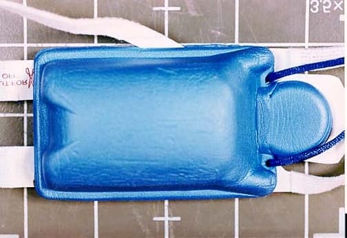
Click to zoom
Application Details
- Equipment Class
- DXX - Part 15 Low Power Communication Device Transmitter
- Date of Grant
- Apr 22, 2002
- Application Purpose
- Original Equipment
- Date of Application
- Apr 22, 2002
- Equipment Note
- Medical Transmitter, DS-1
- Frequency Range
- 608.00000000 - 614.00000000
- Company
- Medical Data Electronics
- Country
- United States
Documents & Files
Document Text
Text extracted from the exhibit documents filed with the FCC. Open a document above to read the original.
Users Manual
PAMTelemetry Transmitter Single Patient Use Patient PreparationProper skin prep and electrode placement iscritical to ensure patient safety and accuratereadings. Follow steps below carefully:1. Shave areas where electrodes w ill be applied. 2. Place lanyard over patient's head and adjust lanyard length accordingly. 3. For adult patients, rub electrode location briskly with abrasive on release liner(see illustration) until skin is pink. Do not usealcohol to prep skin. 4. Apply electrodes to skin, pressing firmly around entire edge of adhesive surface. 5. Remove electrodes from patient when battery is depleted or monitoring not required. 6. Cut lead “LL” where indicated to deactivate transmitter (see illustration). 7. Return transmitter to manufacturer for proper disposal and reprocessing. USER INSTRUCTIONS User Instruction Part Number: 404160 Device may contain remanufactured electronics.WARNING:This transmitter is intended for single patient use.For effective monitoring and to avoid contaminationbetween patients, do not reuse.This Device has not been tested for use duringMagnetic Resonance Imaging (MRI) procedures.Using devices that are connected to patientsthrough lead wires and electrodes during MRIprocedures can result in serious patient burns.Discontinue use if patient develops severe skinirritation.Electromagnetic interference (EMI) may affect theperformance of this device. Special care should betaken when electrosurgical instruments or similardevices are used on a patient wearing anytelemetry transmitter.As with all ECG monitoring, patient motion maycause artifact.Best if used before ( ) shelf life expiration date found on back of device.Operation of this equipment requires priorcoordination with a frequency coordinatordesignated by the FCC for the Wireless MedicalTelemetry Service.
Users Manual
Step 1. While still in package, expose transmitting head of transmitter.Step 2. Fold back both sides of foam programming head to expose programming tab. Do not remove release liners. Step 3. Insert tab into programming port on front of Vision base (see Illustration). Once transmitter is inserted in programming port, system willautomatically provide instructions for finding correct screenprogramming. Step 4. Follow on screen programming instructions.Step 5. After transmitter is programmed, remove from programming port.Step 6. Write patient ID onto device in the space provided.NOTE: To maximize battery life, DO NOT perform Steps 7 and 8 until you are ready to begin patient monitoring. Step 7. While still in package, remove release liners on both halves of programming head. Step 8. Close and press the foam programming head together to activate transmitter. Step 9. Remove transmitter from package, apply to patient. Instructions for Programming the PAM Transmitter WARNING: Once programming of the transmitter is complete, the patient's ID MUST be written on the transmitter to ensurethe vital signs correlate to that particular patient.
Users Manual
ESCORT Vision™ Central Station Operator’s Manual Model 20500 Federal law restricts this device to sale by or on the order of a physician. Medical Data Electronics • •• • 12723 Wentworth Street • •• • Arleta, California 91331-4330 (818) 768-6411 • •• • FAX (818) 768-0759 Medical Data Electronics • •• • Rembrandtlaan 1B, 3723 BG • •• • Bilthoven, The Netherlands Tel: +31 (0) 30 2289711 Fax: +31 (0) 30 2286244 2 TABLE OF CONTENTS Preface .............................................................................................................................. 3 Warranty ........................................................................................................................... 3 Technical Service...............................................................................................................3 Trademarks ....................................................................................................................... 3 Safety Considerations......................................................................................................... 4 Getting Started..................................................................................................................... 7 About your Vision Central Station....................................................................................... 7 Turning the Vision On........................................................................................................ 7 Turning the Vision Off ....................................................................................................... 7 Operating the Touchscreen Display ..................................................................................... 8 Admit a Patient .................................................................................................................. 8 Discharge a Patient.............................................................................................................8 Generate Recording............................................................................................................ 8 Recording Multiple Waveforms.......................................................................................... 9 Generate Continuous Recordings........................................................................................ 9 Cancel Recordings ............................................................................................................. 9 Silence Alarm Tones .......................................................................................................... 9 Set Arrythmia and Vital Sign Alarms .................................................................................10 Adjust BEDSIDE Vital Sign Settings .................................................................................10 Reviewing Stored Data......................................................................................................11 Full Disclosure .........................................................................................................11 Event History............................................................................................................11 Tabular Trend...........................................................................................................12 Graphical Trend........................................................................................................13 Review Data for Discharged Patient ...........................................................................13 Telemetry Transmitter (Guardian Transmitter)....................................................................13 Telemetry Transmitter (Angel Transmitter).........................................................................14 Change Display Format .....................................................................................................19 Recalibrate the Touchscreen Display..................................................................................19 Troubleshooting ..................................................................................................................20 Caring for and Maintaining Your Central Station ..............................................................27 Shipping and Storage ........................................................................................................27 3 Preface The ESCORT Vision Central Station is intended to be used to provide, using a wireless LAN for communication, centralized surveillance and documentation of patient vital sign data and arrhythmia/ST monitoring for a variable number of ESCORT II Bedside Monitors and a variable number of UHF telemetry transmitters in a hospital environment. It is intended for use by healthcare practitioners trained in the use of the equipment only. The ST algorithm has been tested for accuracy of the ST segment measurement data. The significance of the ST segment changes must be determined by a physician. The ESCORT Vision Central Station is intended only as an adjunct to patient assessment. It cannot replace skilled nursing care and proper surveillance. Be sure to carefully read this operator’s manual, all directions for use of the Vision, ESCORT bedside monitors and monitor accessories, and all precautionary information before attempting clinical use of the Vision. Always keep high-risk patients under close surveillance. This operator's manual contains the essential operating instructions and safety warnings for quick and easy operation of the ESCORT Vis io n Ce nt ral Statio n. For co mple te informatio n o n t he e ntire range of ESCORT Vision Central Station operations and features, refer to the ESCORT Vision Central Station Reference Manual . For co mple te informatio n o n se rvic ing t he ce ntral statio n, re fe r to the ESCORT Vision Central Station Service Manual. The information in this document is subject to change without n…
Text truncated - open the document above for the full version.
ID Label/Location Info
CHANNEL PATIENT I.D. Label Location Made in U.S.A. FCC ID: EHCDS1 Patent Pending LOT CODE: EXP: MODEL : DS1 R UCS LR 83658 UL 2 601-1 ! PX7I 2 Arle ta, CA 91331 Medical Data Electronics Rear of Unit (Substrate Not Shown)
ID Label/Location Info
Made in U.S.A. FCC ID: EHCDS1 Patent PendingLOT CODE: EXP:MODEL: DS1 R U CS LR83658UL 2601-1 ! PX7 I 2 Arleta, CA 91331 Medical Data Electronics MDE MEDI CAL DATA ELECTRONI CS a subsi diary of VIASYS Healt hcare
ID Label/Location Info
a subsi di ary of VIASYS Heal th ca re MEDI CAL DATA ELECTRONI CS MDE CHANNEL PATIENT I.D.
Test Report
Page 1 of 30 Report No.: FC02-032 MEDICAL DATA ELECTRONICS TEST REPORT FOR THE MEDICAL TRANSMITTER, DS-1 FCC PART 15 SUBPART C SECTIONS 15.242 AND 15.109 COMPLIANCE DATE OF ISSUE: APRIL 9, 2002 PREPARED FOR: Medical Data Electronics 12723 Wentworth Street Arleta, CA 91331 PREPARED BY: Mary Ellen Clayton CKC Laboratories, Inc. 5473A Clouds Rest Mariposa, CA 95338 P.O. No.: 592ML-144 W.O. No.: 78635 Date of test: April 8-9, 2002 Report No.: FC02-032 This report contains a total of 30 pages and may be reproduced in full only. Partial reproduction may only be done with the written consent of CKC Laboratories, Inc. The results in this report apply only to the items tested, as identified herein. Page 2 of 30 Report No.: FC02-032 TABLE OF CONTENTS Administrative Information ............................................................................................. 3 Summary of Results......................................................................................................... 4 Conditions for Compliance.............................................................................................. 4 Approvals......................................................................................................................... 4 Equipment Under Test (EUT) Description...................................................................... 5 15.31 Voltage Variation .................................................................................................. 5 15.31 Number Of Channels ............................................................................................. 5 15.33 Frequency Ranges Tested ...................................................................................... 5 15.242 Radiated Emissions ................................................................................. 5 15.109 Radiated Emissions ................................................................................. 5 15.203 Antenna Requirements ........................................................................................ 5 15.205 Restricted Bands .................................................................................................. 5 Mode Of Operation.......................................................................................................... 5 Eut Operating Frequency................................................................................................. 5 Equipment Under Test..................................................................................................... 5 Peripheral Devices ........................................................................................................... 5 Report of Measurements.................................................................................................. 6 Table 1: Fundamental Highest Radiated Emission Levels - 15.242(c) ............... 6 Table 2: Six Highest Radiated Emission Levels - 15.242(c)............................... 7 Table 3: Six Highest Radiated Emission Levels - 15.109 ................................... 8 Temperature And Humidity During Testing ................................................................... 11 Measurement Uncertainty................................................................................................ 11 EUT Setup .......................................................................................................................11 Correction Factors ........................................................................................................... 11 Table A: Sample Calculations ............................................................................. 11 Test Instrumentation and Analyzer Settings.................................................................... 12 Table B: 15.35 Analyzer Bandwidth Settings Per Frequency Range.................. 12 Spectrum Analyzer Detector Functions............................................................... 12 Peak ......................................................................................................... 12 Quasi-Peak............................................................................................... 13 Average.................................................................................................... 13 EUT Testing ....................................................................................................................13 Radiated Emissions ............................................................................................. 13 Appendix A: Test Setup Diagram and Photographs........................................................ 14 Equipment Test Setup Diagram........................................................................... 15 Photograph Showing Radiated Emissions ........................................................... 16 Photograph Showing Radiated Emissions ........................................................... 17 Photograph Showing Radiated Emissions ........................................................... 18 Appendix B: Test Equipment List ................................................................................... 19 Appendix C: Measurement Data Sheets .......................................................................... 20 Page 3 of 30 Report No.: FC02-032 CKC Laboratories, Inc. has received Certificates of Accreditation from the following agencies: A2LA (USA); BSMI (Taiwan); Nemko (Norway); and GOST (Russia). CKC Laboratories, Inc has received test site Registration Acceptance from the following agencies: FCC (USA); VCCI (Japan); and Industry Canada. CKC Laboratories, Inc. has received Letters of Acceptance through an MRA for the following agencies: ACA/NATA (Australia); SABS (South Africa); SWEDAC (Sweden); Radio Communications Agency (RA); HOKLAS (Hong Kong); Bakom (Swiss); BIPT (Belgium); Denmark Telestyrelsen; RvA (Netherlands); SEE (Luxembourg) SITTEL (Bolivia); and UKAS (UK). AD…
Text truncated - open the document above for the full version.
Test Setup Photos
PHOTOGRAPH SHOWING RADIATED EMISSIONS Radiated Emissions - Front View PHOTOGRAPH SHOWING RADIATED EMISSIONS Radiated Emissions - Back View PHOTOGRAPH SHOWING RADIATED EMISSIONS Radiated Emissions - Side View
Contact Information
Applicant
Bill Costello(Product Manager)
818 768-6411Fax: 818 768-4197
Technical Contact
CKC Laboratories, Inc.Mary Ellen Clayton
[email protected]1-800-500-4362
5473A Clouds Rest · Mariposa, California · United States
Non-Technical Contact
CKC Laboratories, Inc.Mary Ellen Clayton
[email protected]1-800-500-4362
Test Firm
CKC Laboratories, Inc.Steve Behm
Technical Specifications
| # | Rule Parts | Frequency Range | Power Output |
|---|---|---|---|
| 1 | 15C | 608 MHz - 614 MHz | - |
Other Applications from Medical Data Electronics
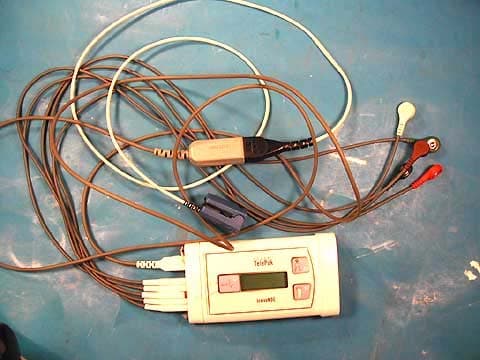
EHC20701
Dec 15, 2004Escort Telepak
Equipment Class
TNT - Licensed Non-Broadcast Transmitter Worn on Body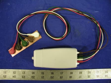
EHCDS2
May 01, 2003Medical Telemetry Transmitter
Equipment Class
TNT - Licensed Non-Broadcast Transmitter Worn on Body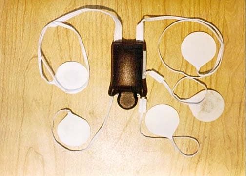
EHCDS
Nov 19, 2001Stickman Transmitter, DS
Equipment Class
DXX - Part 15 Low Power Communication Device Transmitter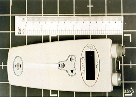
EHC20603
May 25, 2000Telemetry TX
Equipment Class
DXX - Part 15 Low Power Communication Device TransmitterEHC20600A
Feb 01, 1999TNB - Licensed Non-Broadcast Station Transmitter
Equipment Class
TNB - Licensed Non-Broadcast Station Transmitter