EHCDSStickman Transmitter, DS
Medical Data Electronics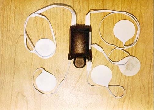
Click to zoom
Application Details
- Equipment Class
- DXX - Part 15 Low Power Communication Device Transmitter
- Date of Grant
- Nov 19, 2001
- Application Purpose
- Original Equipment
- Date of Application
- Nov 11, 2001
- Equipment Note
- Stickman Transmitter, DS
- Frequency Range
- 608.02400000 - 613.96800000
- Company
- Medical Data Electronics
- Country
- United States
Documents & Files
Document Text
Text extracted from the exhibit documents filed with the FCC. Open a document above to read the original.
Users Manual
Medical Data Electronics • 12723 Wentworth Street • Arleta, California 91331-4330 • (818) 768-6411 • FAX (818) 768-2899 Page 1 Operating Instructions for Stickman WARNING: Stickman is intended for single patient use. For effective monitoring and to avoid contamination between patients, discard unit after use. WARNING: As with all ECG monitoring, patient motion may cause artifact. Check lead placement. WARNING: Inappropriate settings for ECG size may adversely affect monitoring. Only modify ECG sizing if necessary for reliable heart rate detection. WARNING: Arrhythmia settings should be carefully checked for effective monitoring. Settings should only be modified by experienced, qualified healthcare professionals. WARNING: Do not turn OFF parameter alarms. In the event of an adverse patient condition, audio alarm will not sound if it has been temporarily silenced or disabled. WARNING: For pacemaker patients, HR detector may continue to count pacemaker artifact during cardiac arrest or some other arrhythmias. Keep pacemaker patients under close surveillance. NOTE: This device complies with Part 15 of the FCC Rules. Operation is subject to the following two conditions: (1) this device may not cause harmful interference, and (2) this device must accept any interference received, including interference that may cause undesired operation. CAUTION: Changes or modifications not expressly approved by the party responsible for compliance could void the user's authority to operate the equipment. Page 2 NOTE: This equipment has been tested and found to comply with the limits for a Class B digital device, pursuant to Part 15 of the FCC Rules. These limits are designed to provide reasonable protection against harmful interference in a residential installation. This equipment generates, uses and can radiate radio frequency energy and, if not installed and used in accordance with the instructions, may cause harmful interference to radio communications. However, there is no guarantee that interference will not occur in a particular installation. If this equipment does cause harmful interference to radio or television reception, which can be determined by turning the equipment off and on, the user is encouraged to try to correct the interference by one or more of the following measures: ! Reorient or relocate the receiving antenna. ! Increase the separation between the equipment and receiver. ! Connect the equipment into an outlet on a circuit different from that to which the receiver is connected. ! Consult the dealer or contact MDE Technical Support for help. Programming Stickman (see also Illustration on Page 10) Step 1. Remove the un-programmed Stickman from package. Step 2. Peel back both sides of foam on rounded section of transmitter to expose programming interface card. Step 3. NOTE: Make sure all popups are closed on the main screen. Insert interface card into connector on front of Vision base. The following message is displayed at bottom of Vision screen: SELECT A PATIENT TILE FOR THIS TRANSMITTER Step 4. Select a patient tile for this transmitter using the following six (6) scenarios as a guide. Scenario #1 Blank Tile – No Patient Admitted and No Signal If the selected tile does not contain an admitted patient and has no signal, the on-screen keyboard displays and says: TRANSMITTER ADMIT: ENTER PATIENT INFORMATION Page 3 a. Using the on-screen keyboard, enter the PATIENT NAME, PATIENT ID , and LOCATION . b. Touch EXIT to begin the programming operation. ADMITTING PATIENT... is displayed at the top of the on-screen keyboard. c. After programming completes successfully, the following message is displayed: TRANSMITTER READY – WRITE <Name> AND <Channel> ON TRANSMITTER Touch OK , remove the transmitter from the Vision base, write patient name and channel number on transmitter and go to Step 5 on page 8. Page 4 Scenario #2 Patient Admitted in Tile and has No Signal If the tile selected contains an admitted patient and has no signal, a popup displays and says: PATIENT CURRENTLY ADMITTED – CONFIRM ASSIGNING TRANSMITTER TO PATIENT <Name> ON CHANNEL <Channel>? a. Touch YES if this is desired patient (touching NO will allow you to discharge patient and admit new patient as described in Scenario #1) . b. After programming completes successfully, the following message is displayed: TRANSMITTER READY – WRITE <Name> AND <Channel> ON TRANSMITTER Touch OK , remove the transmitter from the Vision base, write patient name and channel number on transmitter and go to Step 5 on page 8. Page 5 Scenario #3 Patient Admitted in Tile, has Good Signal and Low Battery Indication If the tile selected contains an admitted patient, has a good signal, and has a Low Battery indication, a popup displays and says: PATIENT CURRENTLY ADMITTED – REPLACE TRANSMITTER ON PATIENT <Name> CHANNEL <Current Channel>? a. Touch YES to replace transmitter. b. After programming completes successfully, the following message is displayed: TRANSMITTER READY – WRITE <Name> AND <New Channel> ON TRANSMITTER Touch OK , the following message is displayed: DEACTIVATE OLD TRANSMITTER PRIOR TO ACTIVATING NEW TRANSMITTER c. Touch OK , remove the new transmitter from the Vision base, write patient name and channel number on transmitter, and deactivate the old transmitter prior to goin g to Step 5 on page 8. Page 6 Scenario #4 Patient Admitted in Tile, has Good Signal and Good Battery Indication If the tile selected contains an admitted patient, has a good signal, and has a good battery indication, a popup displays and says: WARNING! – ACTIVE TRANSMITTER ON PATIENT <Name> CHANNEL <Channel> – CONTINUE? a. Touch YES if you wish to replace transmitter (or touch NO to cancel). b. After programming completes successfully, the following message is displayed: TRANSMITTER READY – WRITE <Name> AND <New Channel> ON TRANSMITTER Touch OK , the following message is displayed: DEACTIVATE OLD TRANSMITTER PRIOR TO ACTIVATING NEW TRANSMITTER c. Touch OK , remove the new trans…
Text truncated - open the document above for the full version.
Cover Letter(s)
CONFIDENTIALITY LETTER Medical Data Electronics 12723 Wentworth St. Arleta, CA 91331 Federal Communicatio ns Co mmission 7435 Oakland Mills Road Columbia, MD 21046 Gentle me n: This letter is to comply with Section 0.457(d)(2)(i) pertaining to confidential material. Medical Data Elctronics would like the following documents regarding this submission for FCC ID: EHCDS to be kept confidential. Block Dia gra m, Circuit Description, Sc he matics . The above material contains trade secrets or technical data, which would customarily be guarded from competitors. We do not want these documents to be accessible to the general public. Sincerely, Bill Costello RF Product Mgr.
ID Label/Location Info
U Medical Data Electronics Arleta, CA 91331 S/N: 4101-1001 FCC ID: EHCDS Made in U.S.A.Patent Pending ! 2 I PX7 C R MODEL: DS EXP: OCT 02 UL 2601-1 LR83658 S BLACK TEXT ON MATTE WHITE POLYESTER UL/CSA RECOGNIZED MATERIAL. TO REAR OF UNIT AT TIME OF MANUFACTURE. FCC I.D. TEXT HEIGHT .07 INCHES. 1.50 IN .50 IN Medical Data Electronics Model: DS FCC Label Description & Location (Rear View of Unit Less Leadwires) October 2001 LABEL PERMANENTLY AFFIXED
Test Report
Page 1 of 53 Report No.: FC01-076 MEDICAL DATA ELECTRONICS TEST REPORT FOR THE STICKMAN TRANSMITTER, DS FCC PART 15 SUBPART C SECTION 15.242/15.209 & FCC PART 15 SUBPART B SECTION 15.109 CLASS B COMPLIANCE DATE OF ISSUE: NOVEMBER 1, 2001 PREPARED FOR: Medical Data Electronics 12723 Wentworth Street Arleta, CA 91331 PREPARED BY: Joyce Walker CKC Laboratories, Inc. 5473A Clouds Rest Mariposa, CA 95338 P.O. No.: 30823 W.O. No.: 77785 Date of test: October 11 - 13, 2001 Report No.: FC01-076 This report contains a total of 53 pages and may be reproduced in full only. Partial reproduction may only be done with the written consent of CKC Laboratories, Inc. Page 2 of 53 Report No.: FC01-076 TABLE OF CONTENTS Administrative Information .............................................................................................4 Summary of Results .........................................................................................................5 Modifications Required for Compliance .........................................................................5 Approvals .........................................................................................................................5 Equipment Under Test (EUT) Description ......................................................................6 Equipment Under Test .....................................................................................................6 Peripheral Devices ...........................................................................................................6 15.33 Frequency Range Tested........................................................................................6 15.209 Radiated Emissions ..................................................................................6 15.109 Radiated Emissions ..................................................................................6 EUT Operating Frequency ...............................................................................................6 Temperature and Humidity During Testing.....................................................................6 Report of Measurements ..................................................................................................7 Table 1: 15.242(c) Field Strength of Fundamental Frequency ............................7 Table 2: 15.242(c) Six Highest Radiated Emission Levels: 4-30 MHz...............8 Table 3:15.242(c)/15.209 Six Highest Radiated Emission Levels: 30-1000 MHz......9 Table 4:15.242(c)/15.209 Six Highest Radiated Emission Levels: 1-7 GHz .....10 Table 5: 15.109 Six Highest Radiated Emission Levels: Receiver 30-1000 MHz.......11 Measurement Uncertainty ................................................................................................12 EUT Setup........................................................................................................................12 Correction Factors............................................................................................................12 Table A: Sample Calculations .............................................................................12 Test Instrumentation and Analyzer Settings ....................................................................14 Table B: 15.35 Analyzer Bandwidth Settings Per Frequency Range ..................14 Spectrum Analyzer Detector Functions ...............................................................14 Peak..........................................................................................................14 Quasi-Peak ...............................................................................................15 Average ....................................................................................................15 EUT Testing.....................................................................................................................15 Radiated Emissions ..............................................................................................15 Transmitter Characteristics ..............................................................................................16 15.203 Antenna Requirements.............................................................................16 15.205 Restricted Bands ......................................................................................16 Appendix A : Information About The Equipment Under Test ........................................17 I/O Ports ...............................................................................................................18 Crystal Oscillators................................................................................................18 Printed Circuit Boards..........................................................................................18 Photograph Showing Radiated Emissions ...........................................................19 Photograph Showing Radiated Emissions ...........................................................20 Photograph Showing Radiated Emissions ...........................................................21 Page 3 of 53 Report No.: FC01-076 Appendix B: Test Equipment List ...................................................................................22 Appendix C: Measurement Data Sheets ..........................................................................23 Band Edge - Low Channel @ 30 kHz..................................................................24 Band Edge - Low Channel @ 100 kHz................................................................25 Band Edge - Low Channel @ 300 kHz................................................................26 Band Edge - High Channel @ 30 kHz .................................................................27 Band Edge - High Channel @ 100 kHz ...............................................................28 Band Edge - High Channel @ 300 kHz ..............................................…
Text truncated - open the document above for the full version.
Test Setup Photos
PHOTOGRAPH SHOWING RADIATED EMISSIONS X-Y Axis Orienta tion PHOTOGRAPH SHOWING RADIATED EMISSIONS Front of Z Axis Orientation PHOTOGRAPH SHOWING RADIATED EMISSIONS Back of Z Axis Orientation
Contact Information
Applicant
Bill Costello(Product Manager)
818 768-6411Fax: 818 768-4197
Technical Contact
CKC Laboratories, IncJoyce Walker
[email protected]1-800-500-4362
5473A Clouds Rest · Mariposa, California · United States
Non-Technical Contact
CKC Laboratories, IncJoyce Walker
[email protected]1-800-500-4362
Test Firm
CKC Laboratories, Inc.Steve Behm
Technical Specifications
| # | Rule Parts | Frequency Range | Power Output |
|---|---|---|---|
| 1 | 15C | 608.024 MHz - 613.968 MHz | 110.00 µW |
Other Applications from Medical Data Electronics
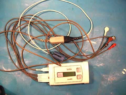
EHC20701
Dec 15, 2004Escort Telepak
Equipment Class
TNT - Licensed Non-Broadcast Transmitter Worn on Body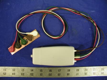
EHCDS2
May 01, 2003Medical Telemetry Transmitter
Equipment Class
TNT - Licensed Non-Broadcast Transmitter Worn on Body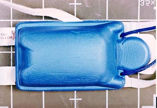
EHCDS1
Apr 22, 2002Medical Transmitter, DS-1
Equipment Class
DXX - Part 15 Low Power Communication Device Transmitter
EHC20603
May 25, 2000Telemetry TX
Equipment Class
DXX - Part 15 Low Power Communication Device TransmitterEHC20600A
Feb 01, 1999TNB - Licensed Non-Broadcast Station Transmitter
Equipment Class
TNB - Licensed Non-Broadcast Station Transmitter