EHC20701Escort Telepak
Medical Data Electronics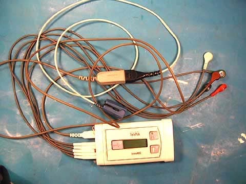
Click to zoom
Application Details
- Equipment Class
- TNT - Licensed Non-Broadcast Transmitter Worn on Body
- Date of Grant
- Dec 15, 2004
- Application Purpose
- Original Equipment
- Date of Application
- Dec 15, 2004
- Equipment Note
- Escort Telepak
- Frequency Range
- 608.00000000 - 614.00000000
- Company
- Medical Data Electronics
- Country
- United States
Documents & Files
Document Text
Text extracted from the exhibit documents filed with the FCC. Open a document above to read the original.
Users Manual
Model Number 20701 Invivo Corporation VISION TelePak TELEMETRY TRANSMITTER OPERATIONS MANUAL i TABLE OF CONTENTS Paragraph NumberPage Number Equipment Classification.............................................................................................................. i Precautions.................................................................................................................................... ii User Responsibility........................................................................................................................v Accessories.................................................................................................................................... vi 1.0Vision Telepak TM Telemetry Transmitter................................................................... 1-1 1.1Introduction...................................................................................................................... 1-1 1.1.1 Warranty.............................................................................................................. 1-1 1.1.2Symbols............................................................................................................... 1-1 1.2Operation of the VISION TelePak Transmitter............................................................... 1-1 1.2.1 Control Keys........................................................................................................ 1-2 1.2.2Display................................................................................................................. 1-2 1.2.3Powering up the transmitter................................................................................. 1-3 1.2.4Configuration Modes........................................................................................... 1-3 1.2.5SpO2 Operation................................................................................................... 1-5 1.3ECG Monitoring.............................................................................................................. 1-5 1.4SpO2 Monitoring............................................................................................................. 1-5 1.5Recording......................................................................................................................... 1-5 1.6Nurse Call........................................................................................................................ 1-5 1.7Powering Down the VISION TelePak............................................................................. 1-5 1.8Cleaning........................................................................................................................... 1-6 EQUIPMENT CLASSIFICATION Classification according to IEC-60601-1 According to the type of protection against electrical shock: Class I equipment. According to the degree of protection against electrical shock: Type CF (defibrillator-proof) equipment. According to the degree of protection against harmful ingress of water: Ordinary equipment (enclosed equipment without protection against ingress of water). According to the methods of sterilization or disinfection: Non-sterilizable. Use of Liquid surface disinfectants only. According to the mode of operation:Continuous operation. Equipment not suitable for use in the presence of a flammable anesthetic mixture with air or with oxygen or nitrous oxide. ii Precautions General Federal law in the USA or Canada restricts this device to sale by, or on, the order of a physician. The Alkaline AA batteries powering the VISION TelePak are consumable components and must be replaced regularly to ensure proper operation. Dispose used batteries properly, according to local regulations. Use only high-quality, 1.5V size AA Alkaline batteries in the VISION TelePak. Use of other batteries may shorten battery life. Read and understand this manual before using the VISION TelePak device. Explosion hazard. Do not use VISION TelePak in presence of flammable anesthetics. Changes or modifications not expressly approved by the party responsible for compliance could void the user's authority to operate the equipment. Electromagnetic interference (EMI) may affect the performance of this device. Special care should be taken when electro surgical instruments or similar devices are used on a patient wearing any telemetry transmitter. This device complies with Part 15 of the FCC Rules. Operation is subject to the following two conditions: 1) this device may not cause harmful interference, and (2) this device must accept any interference received, including interference that may cause undesired operation. ECG Care should be taken to ensure that leadwires remain firmly attached to both transmitter and electrodes. Ensure that electrodes maintain good contact with the patient's skin, and that electrodes are properly placed and connected to unit. Failure to do so may prevent ECG signal from being received, or give incorrect results. For pacemaker patients, HR may continue to count pacemaker artifact during cardiac arrest or other arrhythmia. Keep pacemaker patients under close surveillance. Telemetry should not be used for primary monitoring in applications where the momentary loss of the ECG is unacceptable. If the ECG lead is disconnected from the patient or VISION TelePak, no ECG signal will be available. Poor placement of the ECG leads, or incorrect ECG sizing, could result in a poor or absent ECG signal. Creased or stretched ECG leads, or excessive patient movement, could result in a noisy ECG signal. iii Precautions SpO2 Use only NONIN TM SpO2 sensors specified for VISION TelePak. Incorrect sensor application or use may cause tissue damage or improper operation of the transmitter. Follow directions for use provided. Incident light, poor perfusion, and other factors may affect SpO2 performance and accuracy. Inaccurate measurements or loss of pulse signal may be caused by: •Inc…
Text truncated - open the document above for the full version.
Users Manual
Model Number 20701 Invivo Corporation VISION TelePak TELEMETRY TRANSMITTER OPERATIONS MANUAL i TABLE OF CONTENTS Paragraph NumberPage Number Equipment Classification.............................................................................................................. i Precautions.................................................................................................................................... ii User Responsibility........................................................................................................................v Accessories.................................................................................................................................... vi 1.0Vision Telepak TM Telemetry Transmitter................................................................... 1-1 1.1Introduction...................................................................................................................... 1-1 1.1.1 Warranty.............................................................................................................. 1-1 1.1.2Symbols............................................................................................................... 1-1 1.2Operation of the VISION TelePak Transmitter............................................................... 1-1 1.2.1 Control Keys........................................................................................................ 1-2 1.2.2Display................................................................................................................. 1-2 1.2.3Powering up the transmitter................................................................................. 1-3 1.2.4Configuration Modes........................................................................................... 1-3 1.2.5SpO2 Operation................................................................................................... 1-5 1.3ECG Monitoring.............................................................................................................. 1-5 1.4SpO2 Monitoring............................................................................................................. 1-5 1.5Recording......................................................................................................................... 1-5 1.6Nurse Call........................................................................................................................ 1-5 1.7Powering Down the VISION TelePak............................................................................. 1-5 1.8Cleaning........................................................................................................................... 1-6 EQUIPMENT CLASSIFICATION Classification according to IEC-60601-1 According to the type of protection against electrical shock: Class I equipment. According to the degree of protection against electrical shock: Type CF (defibrillator-proof) equipment. According to the degree of protection against harmful ingress of water: Ordinary equipment (enclosed equipment without protection against ingress of water). According to the methods of sterilization or disinfection: Non-sterilizable. Use of Liquid surface disinfectants only. According to the mode of operation:Continuous operation. Equipment not suitable for use in the presence of a flammable anesthetic mixture with air or with oxygen or nitrous oxide. ii Precautions General Federal law in the USA or Canada restricts this device to sale by, or on, the order of a physician. The Alkaline AA batteries powering the VISION TelePak are consumable components and must be replaced regularly to ensure proper operation. Dispose used batteries properly, according to local regulations. Use only high-quality, 1.5V size AA Alkaline batteries in the VISION TelePak. Use of other batteries may shorten battery life. Read and understand this manual before using the VISION TelePak device. Explosion hazard. Do not use VISION TelePak in presence of flammable anesthetics. Changes or modifications not expressly approved by the party responsible for compliance could void the user's authority to operate the equipment. Electromagnetic interference (EMI) may affect the performance of this device. Special care should be taken when electro surgical instruments or similar devices are used on a patient wearing any telemetry transmitter. This device complies with Part 15 of the FCC Rules. Operation is subject to the following two conditions: 1) this device may not cause harmful interference, and (2) this device must accept any interference received, including interference that may cause undesired operation. ECG Care should be taken to ensure that leadwires remain firmly attached to both transmitter and electrodes. Ensure that electrodes maintain good contact with the patient's skin, and that electrodes are properly placed and connected to unit. Failure to do so may prevent ECG signal from being received, or give incorrect results. For pacemaker patients, HR may continue to count pacemaker artifact during cardiac arrest or other arrhythmia. Keep pacemaker patients under close surveillance. Telemetry should not be used for primary monitoring in applications where the momentary loss of the ECG is unacceptable. If the ECG lead is disconnected from the patient or VISION TelePak, no ECG signal will be available. Poor placement of the ECG leads, or incorrect ECG sizing, could result in a poor or absent ECG signal. Creased or stretched ECG leads, or excessive patient movement, could result in a noisy ECG signal. iii Precautions SpO2 Use only NONIN TM SpO2 sensors specified for VISION TelePak. Incorrect sensor application or use may cause tissue damage or improper operation of the transmitter. Follow directions for use provided. Incident light, poor perfusion, and other factors may affect SpO2 performance and accuracy. Inaccurate measurements or loss of pulse signal may be caused by: •Inc…
Text truncated - open the document above for the full version.
Cover Letter(s)
Response to E04-0000100-1 1. The test report has been revised on page 6 to show the power rating in mV/m. 2. The calculations have been included in the revised test report. 3. The worst case emissions were investigated in the third orthogonal side, and the emissions were near to undetectable. 4. The calculations have been added to the test report. 5. Bandedge plots have been included in the revised test report. 6. Please change the 731 form to show the frequency stability as 7100 Hz. Response to E04-000100-3 SAR 1. The requested information is in Appendix A of the manual. 2. The product tested was a prototype which is identical to the production units as defined in 2.908. 3. 608-614 MHz is not a standard frequency for which the calibration can be conducted. The test was conducted at the next standard frequency of 835 MHz. The conversion factors at the higher frequency result in a more conservative SAR value.
External Photos
Front Back Side 1 Side 2 Side 3 Side 4 Front Ipod Front Xpod EUT Toroid
ID Label/Location Info
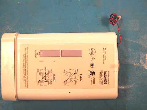
AA ALKALINE ! LR83658 UL 2601-1 USC R BLK RED WHT 3-LEAD RED GRN BRN BLKWHT 5-LEAD with a frequency coordinator designated by the FCC for Operation of this equipment requires the prior coordination the Wireless Medical Telemetry Service. FCC ID: EHC20701 MODEL: 20701 Manufactured by: Orlando, FL 32826 Made in U.S.A. LATEX APPROVALS DRAWN UNLESS OTHERWISE SPECIFIED DIMENSIONS ARE IN INCHES TOLERANCES ARE: + - + - .XXX .005 ANGLES 1 CHECKED SCALESIZEDRAWING NO DO NOT SCALE DRAWINGSHEET 2 OF 2 A REV APPROVED DATE 06-07-04 S4044772.CDR A 404477 OVERLAY, REAR INFORMATION, TELEPAK FULL Ru d y Terranova + - .XX .01 I nvivoMDE Invivo
Internal Photos
PCB Top PCB Bottom PCB 1 PCB 2 PCB 3 PCB 4 PCB 5
Parts List/Tune Up Info
TP # 12-01 REV A Page 1 of 6 TEST PROCEDURE CONTROL # 12-01 Origination Date: 11/05/2004 Approval:__Signature on file_ Revision Date: Current Revision: A ASSY. PART # 404452 TELEPAK PCBA TEST PROCEDURE I. Purpose This document supports and details of the alignment, and subassembly testing of the Medical Data Electronics part 404452 Telepak Transmitter. II. Scope All tests are to be performed by persons trained by Medical Data Electronics employees or authorized trained sub-contractor personnel. III. Test Equipment Required * Power meter Agilent E4418B Power sensor Agilent E9301A Frequency counter Agilent 53181A with opt 001,015 50Ω BNC coax cable Male BNC to female N adapter TF1213 Angel test fixture Red tuning tool MDE part # 268 Black modified tuning tool MDE part # 263 PC with Windows 98 and Data Logger latest software version Straight DB-9 serial cable Bar Code Scanner Intermec Scanplus 1800 ST (optional) GPIB card for PC with drivers (optional) GPIB cables (optional) * Note: Equivalent test equipment may be substituted if necessary IV. Applicable Documents 404452 Schematic V. Procedure 1.0 FIXTURE SETUP 1.1 Plug the AC cord into the fixture, set to Auto mode. 1.2 Connect the PC’s serial connector with the DB-9 cable to the serial connector on the fixture. Connect the optional GPIB cables from the PC GPIB card to the freq. counter and power meter. 1.3 Turn on all test equipment and fixture and allow them to warm up for 30 minutes. 1.4 Calibrate the Power meter and power sensor according to the Setup Appendix. Formatted: Bullets and Numbering TP #12-01 REV A Page 2 of 6 1.5 Press the Recall button on the Frequency counter till Recall 1 appears. Then press the Enter button by the Channel 2 connector. The settings should be set to those given in the Setup appendix. If there is no longer a Recall 1 in the saved setups, see the Setup Appendix to setup the Counter and save the setup. 1.6 Connect power sensor to the test fixture’s TX output connector with the N to BNC adapter. 1.7 Use the BNC coax cable to connect channel 2 of the frequency counter to the –15 dB connector on the fixture marked Freq. Counter. 1.8 Power up the PC and get to the Windows desktop. 1.9 Double click the Smdata.exe Test icon on the PC to start the Data Logger. 1.10 The Stickman Test Fixture window will pop up. Click the INITZ GPIB button if using the GPIB option, otherwise go to step 1.11. 1.11 Click the port control button. The Portclt Class Properties popup window will appear. From the Port: pull down, select the Com port being used to connect to the fixture. The default is Com 2. Click OK when done. 1.12 Click the Open Port button. On the dialog window “Port opened –Com2 – Baud Rate =19200” will appear, if you are using Com2. 1.13 Enter the Test Tech name or Number in the Test Tech box. 2.0 UUT INSTALLATION AND TESTING 2.1 Enter the serial number of the UUT in the serial number box of the Data Logger using a keyboard or a bar code scanner . 2.2 Unlatch the test head door and install the UUT aligning it with the 2 alignment pins. 2.3 Close and latch the door. Then press the green Start button to begin the test. The fixture will begin testing the ECG portion of the PCBA. The Data Logger will display in the dialog window “Fixture state Rx’d”, if not try a different Com Port selection. If there are any failures the fixture will stop at that test and deflate the head removing power from the PCBA. Retry testing the UUT again and if it fails again on the same test remove the UUT and document the failure and route the board for rework or disposal, then skip to Section 2.13 . 2.4 If the UUT completes the ECG portion of the test it will stop at the RF Adjust menu. 2.5 Adjust the power output with VR4 so the current on the display does not exceed 15 ma, but the power meter reads 5.0 dBm minus the loss of the fixture ± 1 dBm. If the limits are turned on, the display will show “Undr Lmt” if the reading is low, “Over Lmt” if it is high, or just the reading if it is in spec. Note: Max power of the Angel PCBA is 5dBm ± 1 dBm. Example: the power meter reads 0.4 dBm + loss of the fixture is 5.1 dBm. The total power of the Telepak PCBA is 0.4 dBm + 5.1 dBm = 5.5 dBm. 2.6 Adjust VR3 for the minimum value read on the fixture display for Bias. The final reading after completing steps 2.7 and 2.8 should be ≤ 20, typical value is 11. TP # 12-01 REV A Page 3 of 6 2.7 Adjust VR2 for the frequency of the test fixture shown in the upper left corner of the fixture display + 0.000,500/-0 MHz (i.e. if RF @610.6 The Freq Counter should read the frequency 610.600,000 + 0.000,500/-0 MHz). Note: Turning VR2 clockwise the frequency goes up. 2.8 Adjust VR1 so the Dev reading on the fixture display reads 515 ± 5. Note: Turning VR1 clockwise the Dev value goes down. 2.9 Repeat the adjustments for steps 2.6 to 2.8 as required. If any portion of the RF adjustment does not pass its final value, press the red Stop button and document the failure and route the board for rework or disposal, then skip to Section 2.13 2.10 Press the green Start button when done tuning to advance the test. 2.11 Verify on the power meter that the TX power output is < –20dBm. Press the green Start button after verifying the value to continue. 2.12 The fixture will complete testing the UUT and then deflate ending testing of the UUT. The fixture display will read UUT passed. The Data Logger will acknowledge the UUT passed and will display “Test record Rx’d” in the dialog window followed by “file opened” and “file closed”. 2.13 To test the next board, go to Step 2.1. If the Board S/N box is highlighted, the Data Logger is ready for another serial number. If it is not highlighted click on the Clear Test Results button, click “OK” for the popup window that appears and the Board S/N will be highlighted to add the new serial number. 2.14 When done testing the job batch or for the shift, all test data will be saved electronically with the ability to be accessed on demand by Medical Dat…
Text truncated - open the document above for the full version.
RF Exposure Info
2867 Progress Place, Suite 4D • Escondido, CA 92029 • U.S.A. TEL (760) 737-3131 • FAX (760) 737-9131 http://www.rfexposurelab.com CERTIFICATE OF COMPLIANCE SAR EVALUATION Medical Data Electronics Dates of Test: November 1, 2004 12723 Wentworth St. Test Report Number: SAR.20041101 Arleta, CA 91331 FCC ID: EHC20701 Model(s): 20701 Serial No.: Prototype Equipment Type: Wireless Medical Telemetry Service Classification: Certification TX Frequency Range: 608 - 614 MHz Maximum RF Output: 8.0 dB Signal Modulation: Frequency Antenna Type (Length): Internal FCC Rule Parts: Part 95H This wireless mobile and/or portable device has been shown to be compliant for localized specific absorption rate (SAR) for uncontrolled environment/general exposure limits specified in ANSI/IEEE Std. C95.1-1992 and had been tested in accordance with the measurement procedures specified in IEEE 1528-2003 and OET Bulletin 65 Supp. C (See test report). I attest to the accuracy of the data. All measurements were performed by myself or were made under my supervision and are correct to the best of my knowledge and belief. I assume full responsibility for the completeness of these measurements and vouch for the qualifications of all persons taking them. RF Exposure Lab, LLC certifies that no party to this application has been denied FCC benefits pursuant to Section 5301 of the Anti-Drug Abuse Act of 1988, 21 U.S.C. 853(a). Jay M. Moulton Vice President © 2004 RF Exposure Lab, LLC FCC ID: EHC20701 Table of Contents 1. Introduction..............................................................................................................3 SAR Definition [5]........................................................................................................3 2. SAR Measurement Setup........................................................................................4 Robotic System............................................................................................................4 System Hardware........................................................................................................4 System Description......................................................................................................4 E-Field Probe ALS-E-020............................................................................................5 3. Robot Specifications................................................................................................7 4. Probe and Dipole Calibration...................................................................................8 5. Phantom & Simulating Tissue Specifications...........................................................9 SAM Phantom.............................................................................................................9 Brain & Muscle Simulating Mixture Characterization...................................................9 Device Holder..............................................................................................................9 6. Body Worn Configurations.....................................................................................10 7. ANSI/IEEE C95.1 – 1992 RF Exposure Limits [2]..................................................11 Uncontrolled Environment.........................................................................................11 Controlled Environment.............................................................................................11 8. Measurement Uncertainty......................................................................................12 9. System Validation..................................................................................................13 Tissue Verification.....................................................................................................13 Test System Verification............................................................................................13 10. SAR Test Data Summary...................................................................................14 See Measurement Result Data Pages.......................................................................14 Procedures Used To Establish Test Signal...............................................................14 Device Test Condition................................................................................................14 SAR Data Summary – 835 MHz Muscle....................................................................15 11. Test Equipment List............................................................................................16 12. Conclusion..........................................................................................................17 13. References.........................................................................................................18 Appendix A – System Validation Plots and Data...........................................................19 Appendix B – SAR Test Data Plots...............................................................................23 Appendix C – SAR Test Setup Photos..........................................................................51 Appendix D – Probe Calibration Data Sheets...............................................................55 Appendix E – Dipole Calibration Data Sheets...............................................................56 Appendix F – Phantom Calibration Data Sheets...........................................................57 © 2004 RF Exposure Lab, LLC Page 2 of 57 FCC ID: EHC20701 1. Introduction This measurement report shows compliance of the Medical Data Electronics Model 20701 FCC ID: EHC20701 with FCC Part 2, 1093, ET Docket 93-62 Rules for mobile and portable devices. The FCC has adopted the guidelines for evaluating the environmental effects of radio frequency radiation in ET Docket 93-62 on August 6, 1996 to protect the public and workers from the potential hazards of RF…
Text truncated - open the document above for the full version.
Test Setup Photos
PHOTOGRAPH SHOWING RADIATED EMISSIONS & OCCUPIED BANDWIDTH Radiated Emissions - Front View PHOTOGRAPH SHOWING RADIATED EMISSIONS Radiated Emissions - Front View PHOTOGRAPH SHOWING RADIATED EMISSIONS Radiated Emissions - Back View PHOTOGRAPH SHOWING TEMPERATURE TESTING
Contact Information
Applicant
Bill Costello(Product Manager)
818 768-6411Fax: 818 768-4197
Technical Contact
CKC Laboratories, Inc.Mary Ellen Clayton
[email protected]800-500-4362
5473-A Clouds Rest · Mariposa, California · United States
Test Firm
CKC Laboratories, Inc.Steve Behm
Technical Specifications
| # | Rule Parts | Frequency Range | Power Output | Emission | Tolerance |
|---|---|---|---|---|---|
| 1 | 95H | 608 MHz - 614 MHz | 6.00 mW | 13K4F1D | 7000.0000000000 Hz |
Other Applications from Medical Data Electronics
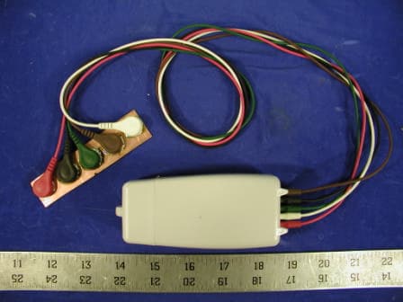
EHCDS2
May 01, 2003Medical Telemetry Transmitter
Equipment Class
TNT - Licensed Non-Broadcast Transmitter Worn on Body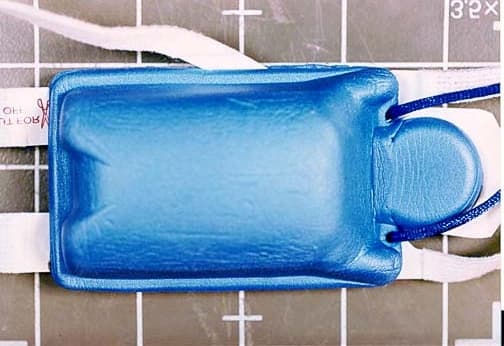
EHCDS1
Apr 22, 2002Medical Transmitter, DS-1
Equipment Class
DXX - Part 15 Low Power Communication Device Transmitter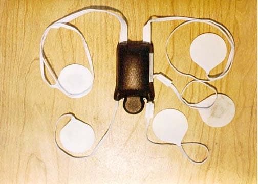
EHCDS
Nov 19, 2001Stickman Transmitter, DS
Equipment Class
DXX - Part 15 Low Power Communication Device Transmitter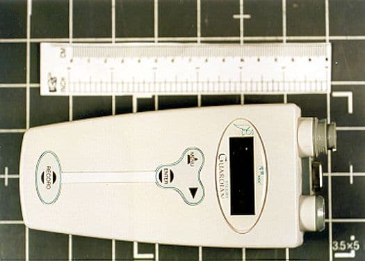
EHC20603
May 25, 2000Telemetry TX
Equipment Class
DXX - Part 15 Low Power Communication Device TransmitterEHC20600A
Feb 01, 1999TNB - Licensed Non-Broadcast Station Transmitter
Equipment Class
TNB - Licensed Non-Broadcast Station Transmitter