F2QSCORPIUSP20MTU2.4 GHz MCE Keyboard with Optical Trackball
Ione International Co., Ltd.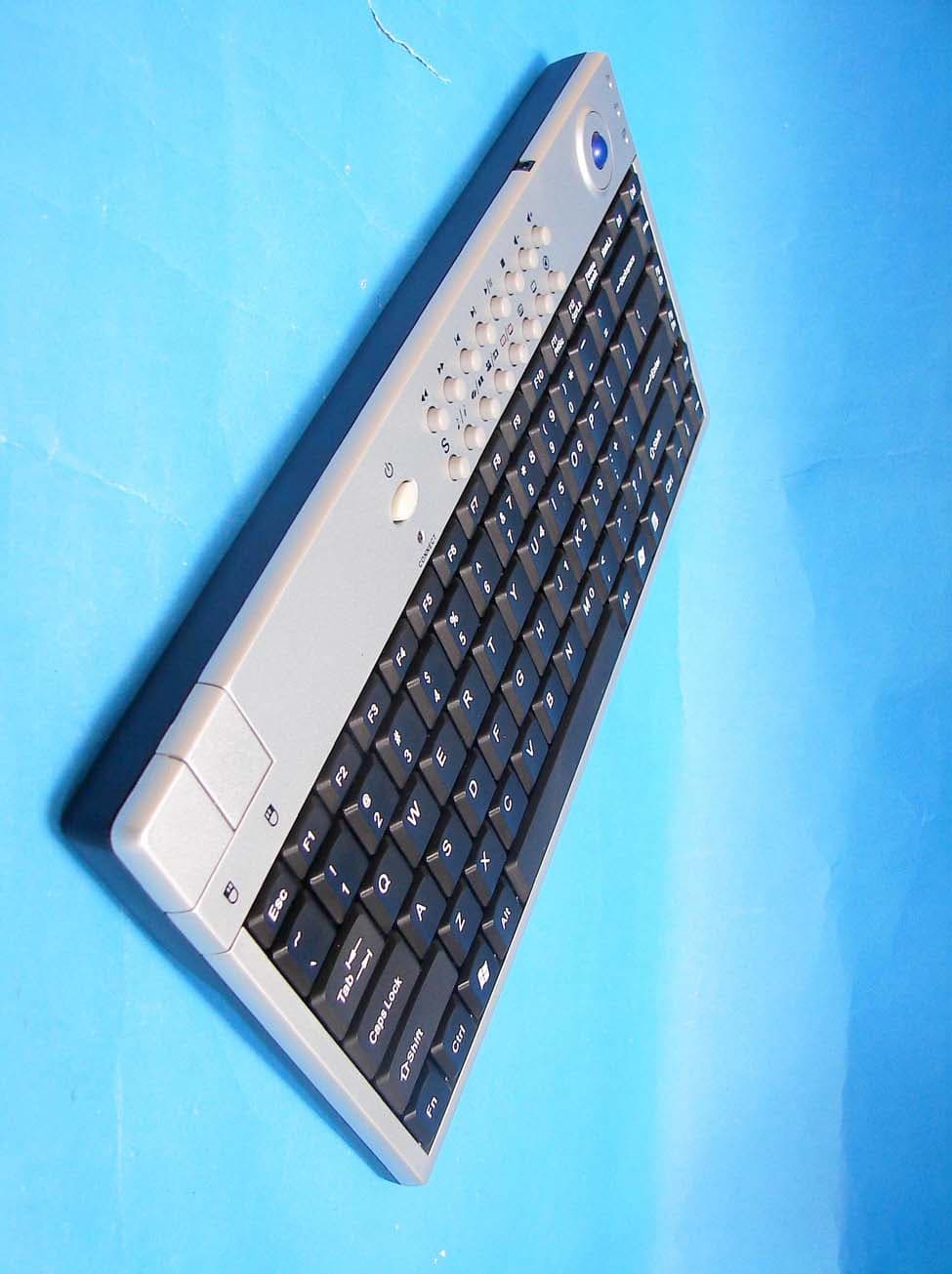
Click to zoom
Application Details
- Equipment Class
- DXX - Part 15 Low Power Communication Device Transmitter
- Date of Grant
- Jul 01, 2007
- Application Purpose
- Original Equipment
- Date of Application
- Jun 26, 2007
- Equipment Note
- 2.4 GHz MCE Keyboard with Optical Trackball
- Frequency Range
- 2405.00000000 - 2468.00000000
- Company
- Ione International Co., Ltd.
- Country
- Taiwan
Documents & Files
Document Text
Text extracted from the exhibit documents filed with the FCC. Open a document above to read the original.
Users Manual
Scorpius-P20MT 2006/10/31 2.4GHz MCE Keyboard with Optical Trackball User Guide Thank you for purchasing Scorpius-P20MT 2.4GHz MCE Keyboard with Optical Trackball. Please read this user guide to help you using this product easily. If you have any questions, please contact us at the website www.ione.com.tw, www.ione-usa.com or www.ione-europe.com. Introduction Scorpius-P20MT is designed for long distance wireless operation on Windows XP Media Center Edition system. The modern fashion design of this MCE keyboard is a perfect input device for your Home Media Center. The trackball pointing device and left-right click buttons work like your mouse on this MCE keyboard, and you can conveniently control the cursor as desired. Plug in Scorpius-P20MT’s mini-receiver to your USB port and you can use this wireless combo without cable cluttering on your desk. The wireless operational range can reach up to 10 meters in open space depending on the radio interference in the environment. With 20 Media Center hotkeys design you can access most of the MCE functions with just one finger. This will save your time of roaming in the menu and easily to locate the media you would like to enjoy. It is suitable for relaxation in your living room at home. Its two-way RF technology will automatically switch its 8 channels when it encountered radio band interference with other surrounded 2.4GHz devices such as another Scorpius-P20MT, Wi-Fi wireless LAN 802.11 a/b/g, Bluetooth, DECT digital telephone, etc. There is no need to worry about the RF interference between Scorpius-P20MT and other 2.4GHz devices. The optical sensor of the trackball is equipped with low power consumption and 3-step smart power saving function. It will enter into rest mode when the trackball is not moving in 1 second to save the power consumption, and further enter into power-down mode after 5 minutes of rest mode for minimum power consumption. It will wake up instantly into normal mode when you press the left or right mouse-button on the keyboard. For using in the USB environment of Windows 2000/XP/XP MCE/Vista Scorpius-P20MT does not require any driver. Just plug and play. However, the MCE hotkeys won’t work, if you are operating under Windows 2000/XP system. Once Scorpius-P20MT is in low battery status you can connect the charging cable to Scorpius-P20MT and mini receiver. The rechargeable batteries in Scorpius-P20MT will receive electrical power from the connected receiver cable. When you do so, please make sure you put rechargeable batteries into the battery holder of Scorpius-P20MT. DO NOT PUT REGULAR BATTERIES INSIDE THE Scorpius-P20MT WHILE YOU CONNECT Scorpius-P20MT AND MINI RECEIVER. IT COULD CAUSE BATTERY EXPLOSURE IF YOU DO SO. Feature .Two-way 2.4GHz RF technology with 8 channels .Wireless operational range can reach up to 10 meters in open space . Battery charging by USB cable Keyboard .Compact size keyboard with highly polished surface .20 MCE hotkeys (4 compound MCE hotkeys) and 2 mouse buttons .Laser engraved keys to avoid characters wearing out (for White version) .High quality rubber membrane key switches to provide excellent tactile feeling .3 LED indicators (Transmitter, Battery Low, Fn) Trackball .Built-in φ14mm optical trackball for precise cursor control. .1000 dpi optical resolution with motion detection up to 37 inches/sec .Low power consumption on working mode .3-step smart power saving function with power-down mode Package Contents: 1. 2.4GHz MCE Keyboard with optical trackball 2. Dongle Receiver 3. Charging Connection Cable 4. 2 x AA Batteries 5. User Guide System Requirements: IBM or compatible PC system Microsoft Windows XP Media Center Edition Pentium IV 2.4G and above CPU is recommended 60G and above hard disk, 256M and above RAM Microsoft Windows XP certified 64M DDR video card Microsoft Windows XP certified MPEG 2 Decoder Hardware Installation Step1: Insert 2 AA batteries into the battery compartment of keyboard with correct polarity. Step2: Please refer to the +, - diagram inside the battery compartment. Step3: Turn on your computer and plug the dongle receiver into a USB port of your computer. Step4: Your computer will detect this USB device automatically. Definition of LEDs: Definition Indicator Description “Transmitter” LED Green To indicate RF transmitting status. “Battery Low” LED Red To indicate “Battery Low” status. “Fn” LED Green Activation of “numerical keypad” function button Key definition Compound Key of MCE (Press with “Shift” key) My TV Go to My TV My Videos Go to My Videos More info Show information about current media or selected item Start Start Media Center or go to Start menu My Music Go to My Music My Photos Go to My Picture/Photos Live TV Switch to live TV if TV is not currently playing. If TV is paused, skip to live programming Record TV Go to recorded TV page DVD Menu Display the DVD menu Guide Go to electronic programming guide Multimedia Key Block Play Play the selected song, Album, Playlist, recorded TV or videos. Pause Pause the currently playing media. Press again to resume Stop Stop playing current media Record Record current TV show or program Next track For Album or Playlist, skip to next song. For recorded TV, skip ahead 29 sec. For DVD, play the next chapter. Previous track For Album or Playlist, play previous song. For recorded TV, go back 5 seconds. For DVD, play the previous chapter. Forward Speed up currently playing media Rewind Rewind currently playing media Mute Mute the sound. Press again to resume the sound Volume up Turn volume up Volume down Turn volume down Right button Same as right button of mouse. Please press it to wake up the optical trackball, if the trackball is in power-down mode Left button Same as left button of mouse. Please press it to wake up the optical trackball, if the trackball is in power-down mode ID Setting The product has been pre-set in ID for radio frequency and the keyboard and dongle receiver are already paired. It is not necessary to do th…
Text truncated - open the document above for the full version.
External Photos
External Photos of EUT--------------------- ------------------------------------------ 1/12 Applicant: Itron Technology Inc. FCC ID: F2QSCORPIUSP20MTU Training Research Co., Ltd., TEL: 886-2-26935155, Fax: 886-2-26934440 External Photos of EUT--------------------- ------------------------------------------ 2/12 Applicant: Itron Technology Inc. FCC ID: F2QSCORPIUSP20MTU Training Research Co., Ltd., TEL: 886-2-26935155, Fax: 886-2-26934440 External Photos of EUT--------------------- ------------------------------------------ 3/12 Applicant: Itron Technology Inc. FCC ID: F2QSCORPIUSP20MTU Training Research Co., Ltd., TEL: 886-2-26935155, Fax: 886-2-26934440
ID Label/Location Info
LABEL Sample and Location information ----------------------------------------- 1/1 Applicant: Itron Technology Inc. FCC ID: F2QSCORPIUSP20MTU Training Research Co., Ltd., TEL: 886-2-26935155, Fax: 886-2-26934440 LABEL Format: LABEL Position: LABEL Size: 60 x 30 mm FCC ID: F2QSCORPIUSP20MTU Model: Scorpius-P20MT This device complies with Part 15 of the FCC Rules Operation is subject to the following two conditions: (1) This device may not cause harmful interference, and (2) This device must accept any interference received, includin g interference that may cause undesired operation LABEL
Internal Photos
Internal Photos of EUT---------------- ------------------------------------------------ 4/12 Applicant: Itron Technology Inc. FCC ID: F2QSCORPIUSP20MTU Training Research Co., Ltd., TEL: 886-2-26935155, Fax: 886-2-26934440 Internal Photos of EUT---------------- ------------------------------------------------ 5/12 Applicant: Itron Technology Inc. FCC ID: F2QSCORPIUSP20MTU Training Research Co., Ltd., TEL: 886-2-26935155, Fax: 886-2-26934440 Internal Photos of EUT---------------- ------------------------------------------------ 6/12 Applicant: Itron Technology Inc. FCC ID: F2QSCORPIUSP20MTU Training Research Co., Ltd., TEL: 886-2-26935155, Fax: 886-2-26934440 Internal Photos of EUT---------------- ------------------------------------------------ 7/12 Applicant: Itron Technology Inc. FCC ID: F2QSCORPIUSP20MTU Training Research Co., Ltd., TEL: 886-2-26935155, Fax: 886-2-26934440 Internal Photos of EUT---------------- ------------------------------------------------ 8/12 Applicant: Itron Technology Inc. FCC ID: F2QSCORPIUSP20MTU Training Research Co., Ltd., TEL: 886-2-26935155, Fax: 886-2-26934440 Internal Photos of EUT---------------- ------------------------------------------------ 9/12 Applicant: Itron Technology Inc. FCC ID: F2QSCORPIUSP20MTU Training Research Co., Ltd., TEL: 886-2-26935155, Fax: 886-2-26934440 Internal Photos of EUT---------------- ----------------------------------------------- 10/12 Applicant: Itron Technology Inc. FCC ID: F2QSCORPIUSP20MTU Training Research Co., Ltd., TEL: 886-2-26935155, Fax: 886-2-26934440 Internal Photos of EUT---------------- ----------------------------------------------- 11/12 Applicant: Itron Technology Inc. FCC ID: F2QSCORPIUSP20MTU Training Research Co., Ltd., TEL: 886-2-26935155, Fax: 886-2-26934440 Internal Photos of EUT---------------- ----------------------------------------------- 12/12 Applicant: Itron Technology Inc. FCC ID: F2QSCORPIUSP20MTU Training Research Co., Ltd., TEL: 886-2-26935155, Fax: 886-2-26934440
Test Report
Test Report ------------------------------------------------------------------------------- 1/27 Report No.: I2615061064, FCC Part 15.249, FCC ID: F2QSCORPIUSP20MTU Training Research Co., Ltd. TEL: 886-2-26935155, Fax: 886-2-26934440 MEASUREMENT REPORT of 2.4GHz MCE Keyboard with Optical Trackball Applicant : Itron Technology Inc. FCC ID : F2QSCORPIUSP20MTU EUT : 2.4GHz MCE Keyboard with Optical Trackball Model : Scorpius-P20MT Test by : Training Research Co., Ltd. TEL : 886-2-26935155 FAX : 886-2-26934440 No. 255, Nan-yang Street, Shijr, Taipei Hsien 221, Taiwan Test Report ------------------------------------------------------------------------------- 2/27 Report No.: I2615061064, FCC Part 15.249, FCC ID: F2QSCORPIUSP20MTU Training Research Co., Ltd. TEL: 886-2-26935155, Fax: 886-2-26934440 CERTIFICATION We here by verify that: The test data, data evaluation, test procedures and equipment configurations shown in this report were made mainly in accordance with the procedures given in ANSI C63.4 (2003) as a reference. All tests were conducted by Training Research Co., Ltd., No. 255, Nan-yang Street, Shijr, Taipei Hsien 221, Taiwan. Also, we attest to the accuracy of each. We further submit that the energy emitted by the sample EUT tested as described in the report is in compliance with the technical requirements set forth in the FCC Rules Part 15 Subpart C Section 15.249. Applicant : Itron Technology Inc. Applicant address : 9F, No. 75, Sec 1, Hsin Tai Wu Road, Hsichih, Taipei Hsien, Taiwan Report No. : I2615061064 Test Date : June 06, 2007 Prepared by: Approved by: Jack Tsai Frank Tsai Conditions of issue : (1) This test report shall not be reproduced except in full, without written approval of TRC. And the test result contained within this report only relate to the sample submitted for testing. (2) This report must not be used by the client to claim product endorsement by NVLAP or any agency of U.S. Government. (3) This test report, measurements made by TRC are traceable to the NIST only Conducted and Radiated Method. Test Report ------------------------------------------------------------------------------- 3/27 Report No.: I2615061064, FCC Part 15.249, FCC ID: F2QSCORPIUSP20MTU Training Research Co., Ltd. TEL: 886-2-26935155, Fax: 886-2-26934440 Tables of Contents CHAPTER 1 GENERAL.................................................................................................................4 1.1 INTRODUCTION...............................................................................................4 1.2 DESCRIPTION OF EUT.....................................................................................4 1.3 TEST METHOD.................................................................................................5 1.4 DESCRIPTION OF SUPPORT EQUIPMENT..........................................................6 1.5 CONFIGURATION OF SYSTEM UNDER TEST.....................................................9 1.6 TEST PROCEDURE.........................................................................................11 1.7 LOCATION OF THE TEST SITE........................................................................11 1.8 GENERAL TEST CONDITION..........................................................................11 CHAPTER 2 CONDUCTED EMISSIONS MEASUREMENTS...........................................................12 2.1 TEST CONDITION & SETUP...........................................................................12 2.2 LIST OF TEST INSTRUMENTS.........................................................................13 2.3 TEST RESULT OF CONDUCTED EMISSIONS....................................................14 CHAPTER 3 TRANSMITTER DUTY CYCLE MEASUREMENTS....................................................15 3.1 TEST CONDITION AND SETUP........................................................................15 3.2 LIST OF TEST INSTRUMENTS.........................................................................15 3.3 TEST INSTRUMENTS CONFIGURATION..........................................................16 3.4 TEST RESULT................................................................................................16 CHAPTER 4 RADIATED EMISSIONS MEASUREMENTS..............................................................18 4.1 TEST CONDITION & SETUP...........................................................................18 4.2 LIST OF TEST INSTRUMENTS.........................................................................20 4.3 TEST RESULT OF RADIATED EMISSIONS.......................................................21 Fundamental Emissions .................................................................................................... 21 4.4 TEST RESULT OF SPURIOUS RADIATED EMISSIONS.......................................22 Radiated Emissions of Horizontal for 30MHz to 25GHz [Lowest Channel] ................... 22 Radiated Emissions of Vertical for 30MHz to 25GHz [Lowest Channel] ....................... 22 Radiated Emissions of Horizontal for 30MHz to 25GHz [Middle Channel] ................... 23 Radiated Emissions of Vertical for 30MHz to 25GHz [Middle Channel]........................ 23 Radiated Emissions of Horizontal for 30MHz to 25GHz [Highest Channel] .................. 24 Radiated Emissions of Vertical for 30MHz to 25GHz [Highest Channel]....................... 24 4.5 TEST RESULT OF THE BANDEDGE.................................................................25 Lowest .............................................................................................................................. 26 Highest.............................................................................................................................. 27 Test Report ------------------------------------------------------------------------------- 4/27 Report No.: I2615061064, FCC Part 15.249, FCC ID: F2QSCORPIUSP20MTU Training Research Co., Ltd. TEL: 886-2-26935155, Fax: 886-2-26934440 Chapter …
Text truncated - open the document above for the full version.
Test Setup Photos
Test Setup Photos ------------------------------------------------------------------------- 1/3 Applicant: Itron Technology Inc. FCC ID: F2QSCORPIUSP20MTU Training Research Co., Ltd., TEL: 886-2-26935155, Fax: 886-2-26934440 Conducted Test Setup Placement: Front View of the Test Configuration Side View of the Test Configuration Test Setup Photos ------------------------------------------------------------------------- 2/3 Applicant: Itron Technology Inc. FCC ID: F2QSCORPIUSP20MTU Training Research Co., Ltd., TEL: 886-2-26935155, Fax: 886-2-26934440 Radiated Test Setup Placement: Front View of the Test Configuration (Charging mode) Rear View of the Test Configuration (Charging mode) Test Setup Photos ------------------------------------------------------------------------- 3/3 Applicant: Itron Technology Inc. FCC ID: F2QSCORPIUSP20MTU Training Research Co., Ltd., TEL: 886-2-26935155, Fax: 886-2-26934440 Radiated Test Setup Placement: Front View of the Test Configuration (Transmission) Rear View of the Test Configuration (Transmission)
Contact Information
Applicant
Ming Wang(Electronic Engineer Supervisor)
Test Firm
Training Research Co., Ltd.Jack Tsai
Technical Specifications
| # | Rule Parts | Frequency Range | Power Output |
|---|---|---|---|
| 1 | 15C | 2.40 GHz - 2.47 GHz | - |
Other Applications from Ione International Co., Ltd.
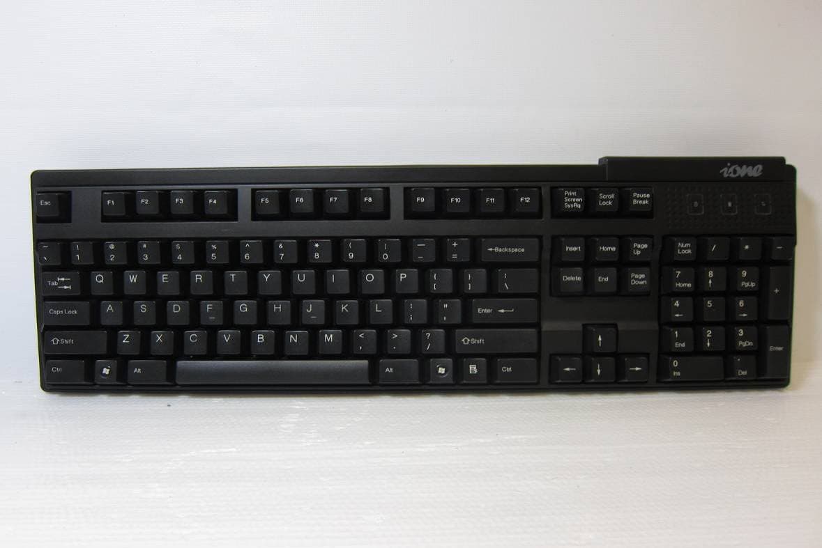
F2QSCORPIUSU9WL
May 02, 2011Wireless Keyboard
Equipment Class
DXX - Part 15 Low Power Communication Device Transmitter
F2QRFLIBRA-S10HU
Dec 09, 2010Wireless Presenter Mouse
Equipment Class
DXX - Part 15 Low Power Communication Device Transmitter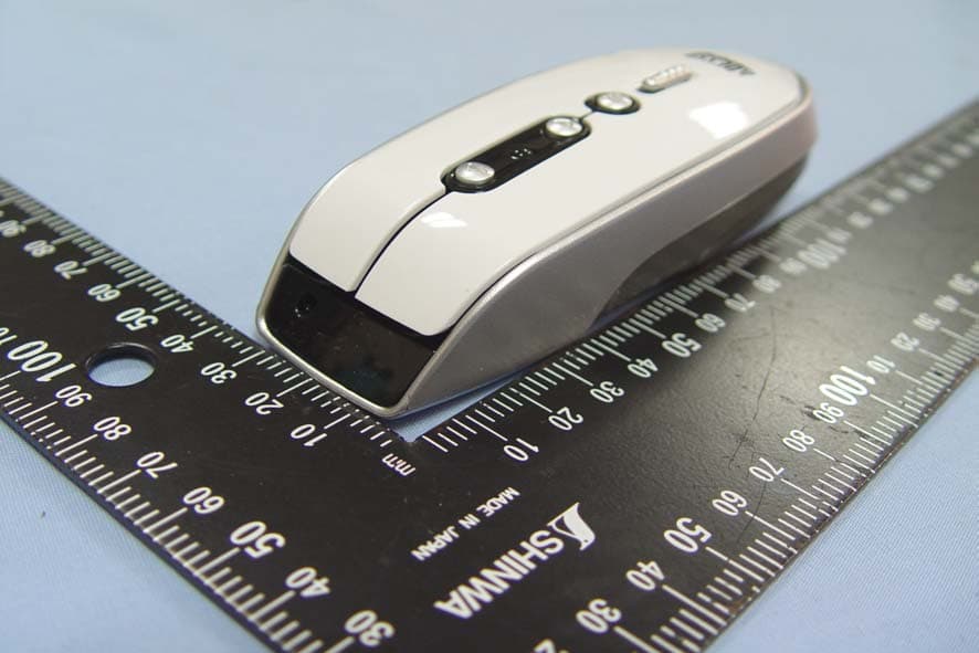
F2QRFLYNXP2
Sep 08, 2010Wireless mouse
Equipment Class
DXX - Part 15 Low Power Communication Device Transmitter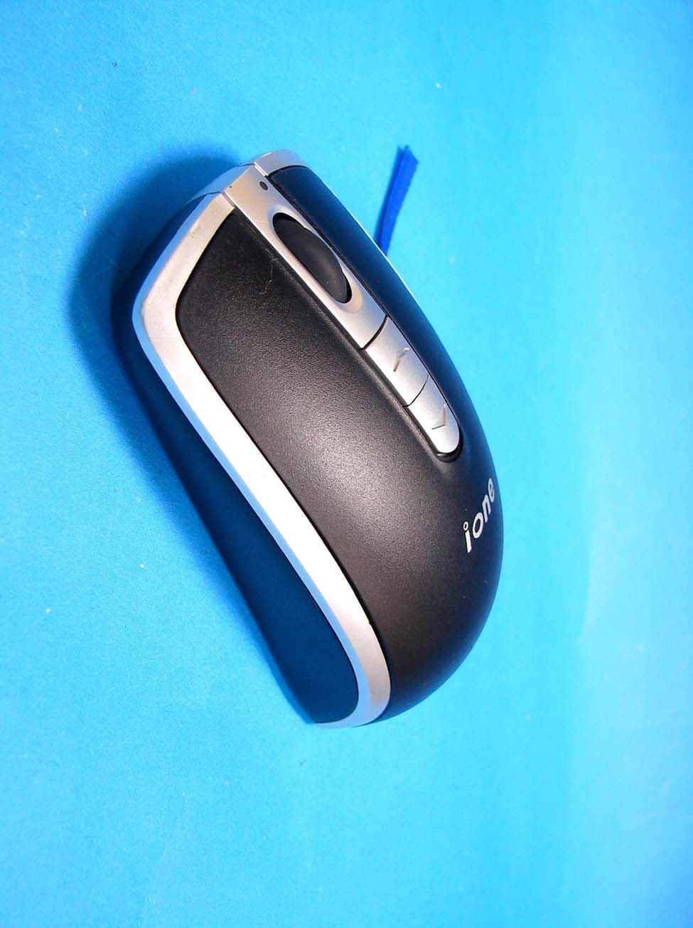
F2QLYNXR7AU
Apr 08, 200727MHz OPTICAL MOUSE
Equipment Class
DXX - Part 15 Low Power Communication Device Transmitter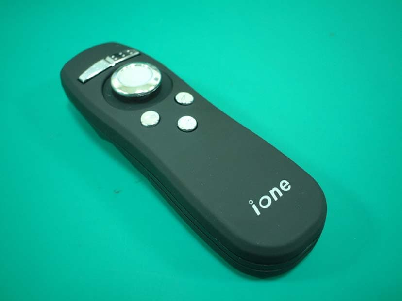
F2QLIBRAP5U
Oct 05, 2006RF 2.4G Presenter Mouse
Equipment Class
DXX - Part 15 Low Power Communication Device Transmitter