F3JSAU1900EPCS Band CDMA Wireless Local Loop Transceiver
Midland Radio Corporation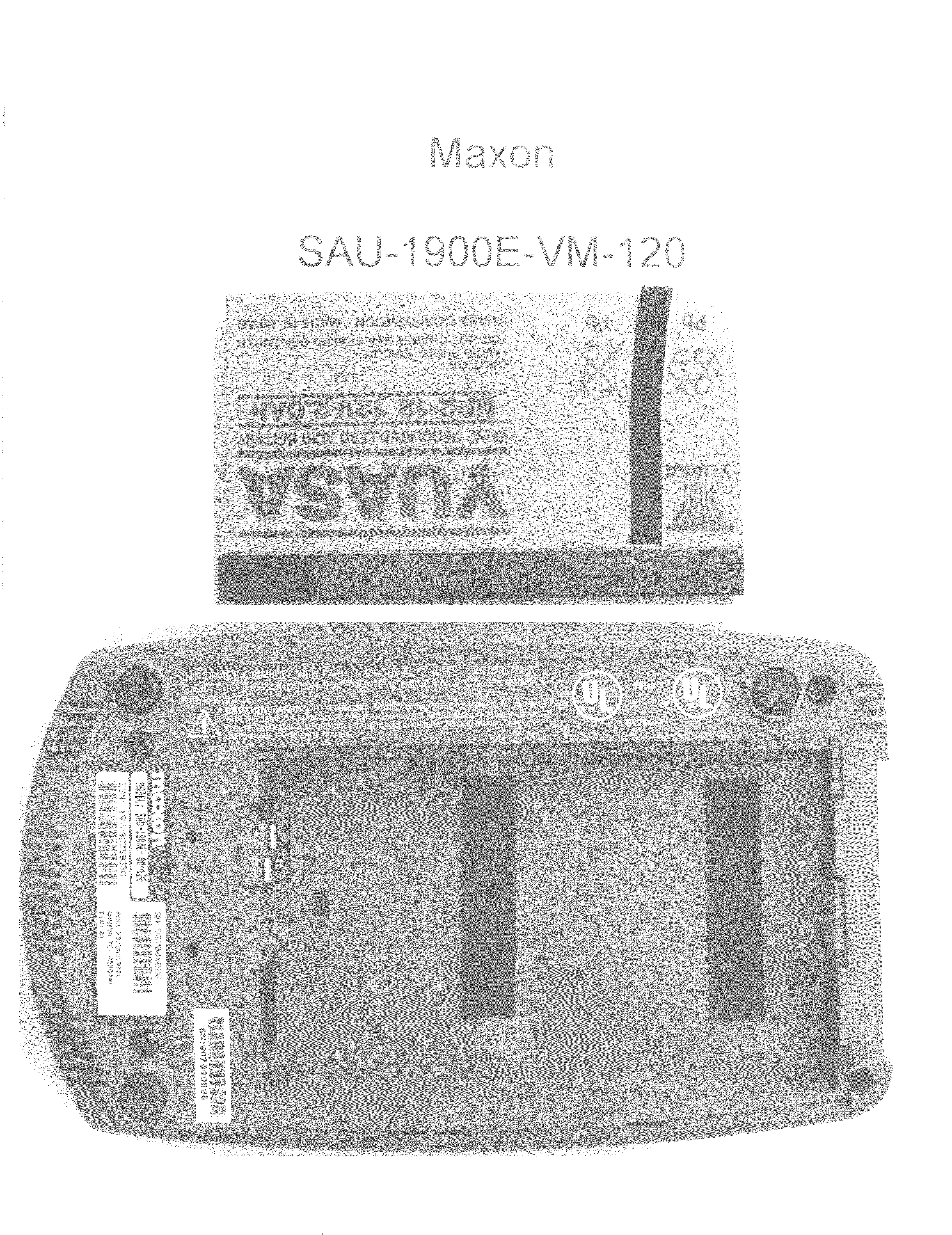
Click to zoom
Application Details
- Equipment Class
- TNB - Licensed Non-Broadcast Station Transmitter
- Date of Grant
- Aug 02, 2000
- Application Purpose
- Original Equipment
- Date of Application
- Apr 20, 2000
- Equipment Note
- PCS Band CDMA Wireless Local Loop Transceiver
- Frequency Range
- 1851.25000000 - 1908.75000000
- Company
- Midland Radio Corporation
- Country
- United States
Documents & Files
Document Text
Text extracted from the exhibit documents filed with the FCC. Open a document above to read the original.
Users Manual
1 SAU-1900E USER’S GUIDE (Draft: Version 0.00) INTRODUCTION Your new MAXON SAU-1900E is designed to provide quality sounding voice communications to other people using almost any regular wire-line telephone in areas where normal ‘wired’ telephone service is not available. By using the same technology as digital cellular telephones, your SAU-1900E, in conjunction with a cellular service provider, replaces the traditional wire-line service with a state of the art wireless telephone service. TABLE OF CONTENTS GETTING STARTED .................................................................................................................................... 2 GETTING TO KNOW YOUR SAU-1900E ..................................................................................................3 SERIAL NUMBER ........................................................................................................................................ 4 SECURITY..................................................................................................................................................... 5 SAFETY ......................................................................................................................................................... 5 Personal Safety............................................................................................................................................ 5 Dangerous Operating Environments ........................................................................................................... 6 SAU-1900E INSTALLATION AND CONNECTION................................................................................... 7 Existing Telephone Service......................................................................................................................... 7 Battery Installation ...................................................................................................................................... 8 Battery Charging ......................................................................................................................................... 9 Where to Install The SAU-1900E ............................................................................................................. 10 Modular Jack Requirements...................................................................................................................... 11 Desktop Installation .................................................................................................................................. 11 Wall-Mount Installation ............................................................................................................................ 12 Connecting the SAU-1900E to Your Telephone(s)................................................................................... 14 SAU-1900E OPERATION ........................................................................................................................... 16 LED Indicators.......................................................................................................................................... 16 Making Calls ............................................................................................................................................. 17 Receiving Calls ......................................................................................................................................... 18 Advanced Features .................................................................................................................................... 18 DATA COMMUNICATIONS/MODEMS/FAXES/ETC. ............................................................................ 18 THE BATTERY, AND WHEN TO REPLACE IT ...................................................................................... 18 Battery Replacement ................................................................................................................................. 19 CLEANING THE SAU-1900E..................................................................................................................... 21 TROUBLESHOOTING GUIDE .................................................................................................................. 22 ACCESSORIES/OPTIONS .......................................................................................................................... 27 TECHNICAL SPECIFICATIONS ............................................................................................................... 28 FCC NOTICE (pending approval) ................................................................................................................ 29 WARRANTY INFORMATION................................................................................................................... 29 FOR YOUR RECORDS ............................................................................................................................... 29 2 GETTING STARTED Make sure that the following items are enclosed in your SAU-1900E box: 1. SAU-1900E unit 2. AC power supply 3. 12V battery 4. Wall mounting bracket 5. Screws for bracket (2 M4x6mm self-tapping, Phillips head screws) 6. 8” (20.3cm) telephone cable for wall mounting 7. 6’ (1.83m) telephone cable for desktop use 8. This user’s guide 9. Warranty card (not shown). If any parts are missing, please contact your service provider or dealer. For your convenience, please keep the SAU-1900E’s original carton and packing material in case of a return or needed warranty work. 3 Note: Please read through this entire manual before starting the installation and use of your SAU-1900E. If you have any questions concerning the installation or use of your SAU-1900E, please contact the dealer where you purchased your SAU-1900E. GETTING TO KNOW YOUR SAU-1900E 1. Antenna 2. Signal LED 3. AC/Battery LED 4. Disruption LED 5. SIMM Card …
Text truncated - open the document above for the full version.
ID Label/Location Info
MADE IN KOREAMADE IN KOREA FCC: F3JSAU1900E CANADA: REV: SN: 904000001 MODEL: SAU-1900E-VM-120 ESN: 197/02359296 SAU-1900E Serial Number Location
Operational Description
Title: J-STD-008 Compatible Single Access Wireless Terminal, Introductory Version. Document Number: PS-SAU-1900E Revision Number: 0.0 Release Date: Mar. 8 th , 1999 Project Engineer: Y.S.Cho This document shows designs, technical data, and/or inventions which are the proprietary rights of Maxon America, Inc. and are disclosed in confidence to the recipient of this print for use by the recipient only in considering or performing a contractual arrangement with Maxon America, Inc. Information presented in this document is subject to change without notice. Maxon America, Inc. 10828 NW Airworld Drive Kansas City, Missouri 64153 PS-SAU-1900E Mar. 8 th , 1999(Rev. 0.0) --- CONFIDENTIAL AND PROPRIETARY --- 2 Table of Revisions Date Revision Changes Mar. 8 th , 1999 0.0 1) First draft release PS-SAU-1900E Mar. 8 th , 1999(Rev. 0.0) --- CONFIDENTIAL AND PROPRIETARY --- 3 TABLE OF CONTENTS 1. General Description of Product. 5 1.1. Basic Features and Design Requirements of Product. 5 2. General Description of the Line Access Unit. 10 2.2. Main board. 10 2.2.1. Functional Description. 11 2.2.2. I/O Definitions. 11 2.2.3. Critical Electrical Characteristics. 11 2.3. Line Interface Unit (LIU). 11 2.3.1. Functional Characteristics. 12 2.3.2. Electrical Characteristics. 15 2.3.3. Applicable Specifications. 16 2.4. Power Supply Module (PSM). 16 2.4.1. Functional Characteristics. 16 2.4.2. Electrical Characteristics. 16 2.5. Battery Management Module (BMM). 17 2.5.1. Functional Characteristics. 17 2.5.2. Electrical Characteristics. 18 2.6. CDMA Module (CDM). 18 2.6.1. I/O Definitions. 18 2.6.2. Electrical Characteristics. 20 2.7. Analog Fax Module Interface(AFMI). 21 2.7.2. Functional Characteristics. 21 3. Software Description. 21 3.1. Telephone Interface. 21 3.1.1. Telephone Interface State Diagram. 22 3.1.2. INCOMING CALL State. 23 3.1.2.1. IDLE State. 24 3.1.2.2. Ring Treatment and Caller ID Data Transmission. 24 3.1.2.2.1. Caller Identification Data Transmission. 25 3.1.3. Call Placement State. 25 3.1.3.1. IDLE State. 26 3.1.3.2. Dial Tone and Digit Collection. 26 3.1.3.3. Gather Dialed Digits Substate. 26 3.1.4. TALK State. 27 3.1.5. VERTICAL FEATURES Interactions. 28 3.1.6. Special Notes. 29 3.1.7. Emergency Numbers. 29 3.2. Hardware Interfaces. 29 3.2.1. Line Interface Module. 30 3.2.1.1. SLIC Operation. 30 3.2.1.2. Caller ID Circuit Operation. 31 3.2.2. Power Supply Module. 31 3.2.3. Battery Management Module. 31 3.2.4. GPIO Expansion Bus. 32 3.2.5. Analog Multiplexer (MUX). 33 3.2.6. LED Indicators. 33 3.3. User Interface Specification. 34 3.3.1. Product Configuration. 34 3.3.1.1. Interface Hardware Description. 34 PS-SAU-1900E Mar. 8 th , 1999(Rev. 0.0) --- CONFIDENTIAL AND PROPRIETARY --- 4 3.3.1.2. Configuration Requirements for J-STD-008 System Interface. 34 3.3.1.3. LAU Application-Specific Hardware Configuration Requirements. 35 3.3.2. Product Test and Maintenance. 38 4. Replaceable and Optional Components. 39 PS-SAU-1900E Mar. 8 th , 1999(Rev. 0.0) --- CONFIDENTIAL AND PROPRIETARY --- 5 1. General Description of Product. The Maxon J-STD-008 Line Access Unit (LAU) is an J-STD-008 compatible transceiver unit which provides an interface between a standard EIA-470 compliant telephone-type device and a J-STD-008 CDMA PCS base station. 1.1. Basic Features and Design Requirements of Product. The following general requirements will be provided by the Maxon J-STD-008 LAU. Electrical Main Power Source: Country-specific ac/dc wall transformer, with input voltages between 90 - 280 Vac, 50-60 Hz, and an output dc voltage of 16 - 30 Vdc (nominal ∼ 19 Vdc). Reserve Power Source: Sealed-cell lead acid battery, ∼ 12 V, rechargeable, with sufficient capacity to provide up to 1.5 hours TALK time and up to 22 hours STANDBY time, when measured from a condition of full charge, at an ambient temperature of 25° C. Battery Recharge Time: The recharge system will provide sufficient capability to fully recharge the reserve battery from maximum allowable discharge to maximum charge level in less than 36 hours. Surge Protection: Product will meet the requirements of paragraph 4.2.7.4.5. of EIA/TIA-571, for Type 2 surges. RF Transmitter Power (maximum): 200 mW, measured at antenna connector. Antenna Interface: 50 ohms Power Fuse: Internal, not accessible by the customer.. Mechanical Shock: The unit shall be designed to withstand the drop requirements of EIA/TIA-571, paragraph 4.1.1.1.3.- 3.a., which specifies single face drops from 6” and single corner drops from 3” onto a tiled surface, with battery installed. Vibration: Required to survive typical transportation and shipping induced vibrations, as defined by paragraph 4.1.1.2. of EIA/TIA-571, with battery removed. The battery is not covered by this specification. PS-SAU-1900E Mar. 8 th ,1999 (Rev. 0.0) --- CONFIDENTIAL AND PROPRIETARY --- 6 Dimensions: Approximately 9” x 5” x 2”. Weight: ∼ 3.75 pounds, with battery installed. Transformer weight is ∼ 2.25 pounds. Connectors: One (1) dc power input connector. Two (2) RJ-11 parallel female telephone connectors. One (1) mini-DIN programming interface connector. One (1) BNC-type female RF antenna connector. Internally mounted plated-contact battery connector. One (1) country-specific telephone cable to convert between RJ11 and country specific telephone interface. Antenna (fixed): Monopole, λ/2 wavelength, adjustable in z-plane, removable, with shrouded BNC RF connector. Antenna (remote): To be defined after further field evaluation. Indicators: One (1) LED - In Service. Shows: • No PILOT Channel (LED off) • Marginal PILOT Channel (LED blink) • Good PILOT Channel (LED on) The Frame Error Rate will be used as the Pilot Quality indicator. The FER which defines “marginal” Pilot status will be software-programmable. One (1) LED - Power Status / Battery Status. Shows: • No Power (LED off) • AC Power (LED on) • Battery Power (LED blink) One (1) LED - Disruption Indication. Indicates failure of internal fuse when ON. General Per…
Text truncated - open the document above for the full version.
Operational Description
SAU-1900E CIRCUIT DESCRIPTION & THEORY OF OPERATION Product Description: SAU-1900E Wireless Local Loop The function of the SAU-1900E is to provide a wire-free interface between a Telephone Service Provider and the telephone wiring in a home or business. Up to 4 Telephones (or equivalent telephone-like loads) may be connected through up to 1000 Feet (~300 meters) of wire to the SAU-1900E to support a single-line (single phone number) telephone service. The SAU-1900E interfaces to the Public Switched Telephone Network (PSTN) via the 1900 MHz CDMA Cellular Phone Interface per IS-98A. The SAU-1900E provides all features associated with a standard ‘Plain Old Telephone System’ (POTS), plus Enhanced Features including the following: Telephone Battery Voltage (-60 to -68VDC), Telephone RINGING Voltages (40 Vrms minimum), Call Progress Signaling (Dial Tone, Stutter Tone, Receiver Off-Hook, Busy Signal, etc.) Caller-ID Signaling per GR-30-CORE, Call Waiting, Cancel Call Waiting, 3-Way Calling, Call Forwarding, and Cancel Call Forwarding. An optional expanded feature of the SAU-1900E is the ability to add an analog modem to the telephone line. This allows for the addition of an analog fax machine or a personal computer equipped with a modem. The following major functional blocks accomplish these features of the SAU-1900E: a. Subscriber Loop Interface Circuit b. 12V Battery Management c. Caller-ID FSK Generator d. Interface Circuitry e. DC/DC Power Supply f. CDMA RF and Baseband Interface f.1. Receiver f.2. Transmitter f.3. Synthesizer f.4. Baseband ASIC f.5. Mobile Station Modem g. MDL-1 Fax/Data (Optional) SAU-1900E CIRCUIT DESCRIPTION & THEORY OF OPERATION SUBSCRIBER LOOP INTERFACE CIRCUIT (SLIC): The Subscriber Loop Interface Circuit (SLIC) provides the means to transfer the voice-band audio signals between the CDMA board and the Telephone line. It also uses the output of the DC Power supply to provide telephone line power and power for ringing telephone extensions. All of these functions are accomplished via a single IC (U501) with external components selected to establish the desired operating parameters. A more detailed description follows: Operating Modes: The SAU controller (located on the CDMA board) establishes the following operating modes by setting the GPIO (and/or GPIO_Expansion) lines to an appropriate state. 1. Low Power Scan: In this state, the SAU controller configures the DC/DC converter to supply a – 65VDC to the Battery Input pins of U501. All other internal circuits, except for the off-hook detector, are turned off to conserve power. The SAU will be placed in this state when U501 indicates that all attached telephone-like loads are in an On-Hook (high DC impedance) condition. 2. Powerup, Forward: This is the normal condition when at least one phone is Off-Hook and a conversation is either in-progress or in the process of being established. The DC/DC power supply is configured for -24 Vdc (rather than -65 Vdc) to conserve power (for increased talk-time on battery power) and to reduce heat dissipation in U501. While in this mode, the SLIC acts as a DC Current Source to provide a 30 mA loop current for powering the telephone. In this state the SLIC IC converts AC Loop Current Signals from a telephone into AC Voltage Signals for transmission to the CDMA CODEC. In addition it operates as a signal amplifier for transmitting voice band analog signals received from the CDMA CODEC to the low impedance telephone receiver. 3. Powerup, Reverse: Same as the state listed above, except the Tip and Ring voltage polarities are reversed from normal {normally Tip is more positive than the Ring line}. This state is infrequently used, typically for signaling equipment other than telephones, which may also be attached to a telephone line. Normal telephone operation is unaffected by Tip/Ring polarity. 4. Ring State: When configured for this mode, and with the DC/DC power supply configured to provide -65 Vdc, the SLIC can apply a 20 Hz, 40-55 Vrms Ring signal to alert a telephone user of an in-coming call. In addition, U501 will monitor the ring current to determine when the phone is taken off-hook so that the SAU controller can terminate the ring signal and the Powerup Forward state can be established. Contrary to standard wireline ringing signals, wherein a Telephone Central Office supplies a 90 Vrms ringing signal which is superimposed upon a battery voltage of -48 Vdc, the SAU-1900E produces the ring signal by reversing the tip/ring voltage at a 20 Hz rate. Wave shape is controlled to produce a balanced trapezoidal waveform with a peak-to-peak swing of approximately 120 Vpp and a RMS voltage between 40 Vrms and 55 Vrms. This waveform is sufficient to ring all telephone types (including older phones with electromechanical ringers) under short loop length (< 100 meters) applications. In addition, up to 4 Ringer Equivalent Network (REN) loads may be simultaneously attached while still providing the minimum 40 Vrms ringing signal. 5. Disconnect State: During this mode of operation, the SLIC is put into a low power mode and the Tip/Ring lines put into a high impedance condition (> 100K Ohms). This state is applied for approximately 800 mSec after receipt of a far-end disconnect message to signal telephone answering machines (and other, similar equipment) to stop recording and to go into an On-Hook condition. Satisfactory audio performance relies upon the ability of this circuit to provide an electrical interface to a telephone which adequately emulates that provided by standard whirling telephone networks. The key features that must be controlled are AC Termination Impedance, Transmit Gain (Telephone Microphone Output to Codec Input direction), Receive Gain (Codec Output to Telephone Speaker direction), and Hybrid Balance. AC Impedance: The SAU is designed to apply a typical telephone network AC load to an attached telephone. Ideally, the SAU will present an impedance which can be modeled as a 270 Ohm…
Text truncated - open the document above for the full version.
Parts List/Tune Up Info
Active Parts for SAU-1900E Main board: Reference: Identifier: Function: Q811 KTC4376Y Current source for Disruption LED Q805 MMSF3P03 Battery power switch Q808 KTA1504 Establishes turn off voltage for battery control switch Q804 KRC104 Battery charge control switch Q807 KRC104 Battery turn off switch Q901 KRC104 Multiplexer enable switch Q902 KRC104 BATT LED control switch Q905-Q909 KRC104 Open collector logic inverters Q806, Q808, Q810 KTC3875 Battery power control switch circuit Q812 KTC3875 Current source for Disruption LED Q801-Q803 MJD32 Battery charging current, series pass transistors Q903 KRA101 Current source for BATT_SIGN LED Q904 KRA101 Current source for Signal LED Q910 KRA101 ON-Off switch for DTMF decoder U905 U503 KIA358 Transmit and Receive gain amplifier for SLIC U501 U702 KIA358 Low pass filter amplifier for Caller-Id generator U701 U801 KIA358 DC voltage control for Battery Charge float voltage circuit U501 LUCL8560 Subscriber line interface circuit U502 ATTL7591 Isolation and surge protection IC for SLIC IC U501 U701 SC429130 Masked 68HC05, Generates Caller-ID U901-U902 MC14094 Serial-to-parallel port expanders U905 MC145436 DTMF decoder U802 LP2951 Precision voltage regulator for battery float charge circuit D806 MMBZ5230 4.7V ZENER diode D801 MMBZ5226 3.3V ZENER diode D805 MMBZ5237 8.2V ZENER diode D803 KDS181 BATT_OFF control line protection D901 KDS181 Wired OR gate for MSM_RXD (5V) and FAX_TXD control lines D902 KDS181 Wired OR gate for RFR (5V) and RFR (FAX) control lines D802 MBRD640 Wired OR gate for source of SYS_POWER D807 EC15QS04 Protection diode for battery charge path DC-DC Converter board: Reference: Identifier: Function: U601 MAX797 5V Step-down DC-DC Converter D601 BAT54C Boost circuit supply diode Q601 MTD20N06 High side MOSFET switch for 5V DC-DC converter Q602 MTD20N06 Low side MOSFET switch for 5V DC-DC converter D602 MBRS360 Diode rectifier for 5V DC-DC converter U602 MAX774 Adjustable inverting DC-DC controller Q603 MTD20P06 MOSFET switch for inverting DC-DC converter D603 MURS160 Diode rectifier for inverting DC-DC converter Q604 RK7002 MOSFET switch for adjusting voltage level of inverting DC-DC converter Q605 KRC104 Bipolar transistor circuit to switch inverting DC-Dc converter on or off MDL-1 Board: Reference: Identifier: Function: D1 KDS181 switching diode for reset line Q1-Q3 KRC104 Digital control line switches U1-U4 KIA358 Buffer and Filter amplifiers U5 AT24C02AN EEPROM for NV Data U6 KIA7045F Voltage sensor speed-up for U15 reset line U7 MC74HC00AD NAND Gate logic for digital controls U8 AT27C256R EPROM for U15 U9 UM62256DM RAM for U15 U10 RC336ACFA/ Modem IC R6749-25 U11 AT27C010A ROM for U10 U12 KM68257CJ RAM for U10 U15 MC68HC11F1 Micro Controller IC CDMA BOARD: Reference: Identifier: Function: Q6 BFP420 Low noise RF amplifier. Q2 FMMT717 Series pass transistor. Q1 KRC104 Digital control switch. Q3, Q4, Q11 KRC404 Digital control switches. U16 TLV320AC36 CODEC IC U19 TC7SO4FU Logic inverter IC. U9 KM68V2000 SRAM IC U15 24LC65T EEPROM IC U23 LMC7111B1M5X Op-amp buffer IC. U17 AM29L800BT Flash memory IC. U3 PMB2333R Mixer/Amplifier IC U14 TQ5M31 Frequency down converter IC. U8 Q5500 RX AGC amplifier. U2 Q5505 TX AGC amplifier. U1, U18, U22, U24 ILC7082AIM5-33 3.3V regulator IC. U5, U7, U10 ILC7082AIM5-36 3.6V regulator IC. U6 LMX2336L Phase locked loop IC. U13 TC7S14FU Gate inverter IC. U11 MSM2300 Mobile station monitor IC. U4 RF2153 RF power amplifier IC. U12 Q5312 I-3S2-BBA2 BASEBAND ASIC IC. U20 MC14504BD Logic level converter IC. IS1 CEO731R88DCB Isolator IC. VCO1 UCVA3X129A Voltage controlled oscillator. D6, D8 DA204U-T106 Protection diodes. D7 BAT74 Power level detector. D5 KDS181 Protection diode. D10 RB751V-40 Protection diode. D1-D4 BB149 VARACTOR diodes. D11 KDS160 Protection diode. TCX1 VCTCXO204C1 Voltage controlled temperature compensated crystal oscillator. Manufactures data sheets are provided for all of these components.
Parts List/Tune Up Info
Filename: L:\Project\2000\p0040007\Exhibits\Alignment_Procedure.DOC Author: Daniel R. Barbour SAU-1900E ALIGNMENT PROCEDURE The SAU-1900E is a CDMA Digital Cellular Receiver/Transmitter covering the frequency range from 1850-1910 MHz (Transmit) and 1930-1990 MHz (Receive). The system design and infrastructure normally controls the SAU-1900E transmitted power level and frequency within required specifications, however initial alignment is performed to constrain the open-loop output power levels to an acceptable range. Alignment of the unit is entails loading correction factors into non-volatile memory for setting minimum and maximum transmit power levels and to ensure that open-loop power levels are maintained within the limits specified in IS-98A by entering a table of AGC control settings. This alignment is performed at initial manufacture and after repair or replacement of the RF section or following replacement of the non-volatile memory. All alignment procedures are performed under software control of the SAU-1900E and specialized CDMA Test Equipment. The equipment required to Align the SAU-1900E and a description of the procedures is provided below: EQUIPMENT: a. IBM PC Compatible: ‘386 or higher chipset running MS-DOS 3.1+ (or equivalent DOS environment running under Windows 3.1/Windows 95). & VGA (or equivalent) monitor. n w/Keithley Metrabyte KPC-488.2 IEEE-488 Interface Board n 1ea IEEE-488 Cable (User determined length) n RS-232 Adapter Cable. (9pin to 9pin cable is typical, although configuration of local PC may require a 25pin-to-9pin cable or use of 9pin-to-25pin adapter). n SAU-1900E RS232 Interface Adapter (9pin-to-circular din adapter with signal conversion from RS232 levels to TTL levels). b. CDMA Mobile Test Set (One of the following options): 1. Tektronix (or Rohde&Schwarz) CMD 80 Digital Radio Communication Tester). Or, 2. Hewlett Packard HP8924C CDMA Mobile Station Test Set Filename: L:\Project\2000\p0040007\Exhibits\Alignment_Procedure.DOC Author: Daniel R. Barbour c. SAU-1900E Calibration Software. (Use software applicable to the particular CDMA Mobile Test Set being used): 1. SAUCAL_T.EXE; Release Version 1.0 {For use with the Tektronix CMD 80} OR, 2. SAUCAL_H.EXE; Release Version 1.0 {For use with the HP8924C} d. EMI Shielded Enclosure (Optional if testing is performed in a locale where there is no active AMPS stations). The enclosure should provide 50 dB (or greater) attenuation over the TX/RX frequency bands. e. AC/DC Power Adapter (18-19 Vdc nominal @ 900 mA minimum; 2.1mm I.D. 5.5mm O.D.) f. Double Shielded Coaxial Cable (Antenna Cable): {Cable loss should be measured prior to testing}. SETUP SAU-1900E EMI Shield AC/DC RS232 Adapter Power Serv ice PC Antenna IEEE-488 CDMA Test Set Filename: L:\Project\2000\p0040007\Exhibits\Alignment_Procedure.DOC Author: Daniel R. Barbour PROCEDURE: 1. Connect equipment per SETUP Diagram shown above. 2. Power up the PC, CDMA Test Set, and SAU-1900E. If necessary, perform any applicable auto-calibration procedures on the CDMA Test Set and let the equipment warm-up per the manufacturer’s recommendations. 3. Load and run the applicable calibration software. 4. When the calibration program starts, enter the following data at the screen prompts: n Prompt: “SELECT LINE PRINTOUT”; select “PRINTER IS OFF” n Prompt: “PUT OPERATOR CODE”; press <ENTER> with no data then press <ENTER> again to confirm. n Prompt: “SELECT STOP OR CONTINUE ON FAIL”: select “CONTINUE ON FAIL” n Prompt: “TYPE PRODUCTION NUMBER”; type in unit Serial Number, then press <ENTER> to confirm. The software will then put the CDMA Test Set into REMOTE operation via the IEEE- 488 Bus and will communicate with the SAU-1900E to monitor its performance and to load calibration data. Upon completion of the test, the program will store the test results in file DATA.TXT on the computer hard disk. This file should be copied to a floppy (Labeled with the Serial Number of the SAU-1900E) for future records. A typical report is shown below for reference: Example DATA.TXT Calibration Report File: {FOR REFERENCE ONLY} Pass 1 ESN Check C50C0002 Pass 2 SW Version PAMK4 Pass 3 Registration Passed Pass 4 Minimum Transmit Power Calibration -51.79 dBm Pass 5 Maximum Transmit Power Check 24.63 dBm Pass 6 Average RX/TX_AGC value at -106 dBm -26.00 684.00 Pass 7 Average RX/TX_AGC value at -95.4 dBm -16.00 676.00 Pass 8 Average RX/TX_AGC value at -84.7 dBm -1.00 604.00 Pass 9 Average RX/TX_AGC value at -74.1 dBm 14.00 532.00 Filename: L:\Project\2000\p0040007\Exhibits\Alignment_Procedure.DOC Author: Daniel R. Barbour Pass 10 Average RX/TX_AGC value at -63.4 dBm 31.00 464.00 Pass 11 Average RX/TX_AGC value at -52.8 dBm 48.00 404.00 Pass 12 Average RX/TX_AGC value at -42.1 dBm 63.00 336.00 Pass 13 Average RX/TX_AGC value at -31.5 dBm 77.00 272.00 Pass 14 Average RX/TX_AGC value at -20.8 dBm 83.00 216.00 Pass 15 CDMA CALIBRATION CHECK @ - 65 dBm -9.85 dBm Pass 16 Maximum Transmit Power Calibration 23.71 dBm Pass 17 Minimum Transmit Power Check -51.72 dBm Pass 18 RX Offset $66 Pass 19 TX Offset $8A Pass 20 Tx 0,0,8,9,9,9,9,9,9,9,9,9,9,9,9,8,9,8,8 Pass 21, 7,8,7,9,8,9,8,8,8,8,9,18,19,19,19,0,0 Pass 22 Rx 5,5,7,8,7,8,8,9,8,9,7,8,7,7,3,3 Pass 23 Max Power Value: $99 (153) Pass 24 Min Power Value: $89 (137) Pass 25 Failed Test's: Pass 26 Program Run Time 5. Alignment is complete after successful termination of this programs (No Fails).
RF Exposure Info
FCC ID: F3JSAU1900E MFA p0040007, d0040035 Date: April 17, 2000 Federal Communications Commission Via: Electronic Filing Attention: Authorization & Evaluation Division Applicant: Maxon America, Inc. Equipment: SAU-1900E-VM-120 FCC ID: F3JSAU1900E FCC Rules: 24 and 47 CFR 1.1307, Environmental Assessment Gentlemen: On behalf of the Applicant, enclosed please find the Supplemental Test Data Report, the whole for Environmental Assessment (MPE) of the referenced equipment as shown. We trust the same is in order. Should you need any further information, kindly contact the writer who is authorized to act as agent. Sincerely yours, William H. Graff, Director of Engineering enclosure(s) cc: Applicant WHG/cvr FCC ID: F3JSAU1900E MFA p0040007, d0040035 Sub-part 1.1307: SUPPLEMENTAL REPORT ENVIRONMENTAL ASSESSMENT General Population / Uncontrolled Exposure, Maximum Permissible Exposure EQUIPMENT IDENTIFICATION Maxon America, Inc. FCC ID: F3JSAU1900E DATE OF REPORT April 17, 2000 SUPERVISED BY: William H. Graff, Director of Engineering FCC ID: F3JSAU1900E MFA p0040007, d0040035 TABLE OF CONTENTS RULEDESCRIPTIONPAGE . Test Report 1 . Identification of the Equipment Under Test 2 . Standard Test Conditions and Engineering Practices 4 1.1310 Environmental Assessment 5 FCC ID: F3JSAU1900E MFA p0040007, d0040035 PAGE NO.1of9. Required information per ISO/IEC Guide 25-1990, paragraph 13.2: a) TEST REPORT (SUPPLEMENTAL) b) Laboratory: (FCC: 31040/SIT) (Canada: IC 2044) M. Flom Associates, Inc. 3356 N. San Marcos Place, Suite 107 Chandler, AZ 85225 c) Report Number: d0040035 d) Client: Maxon America, Inc. 10828 N.W. Air World Dr. Kansas City, Missouri 64153 e) Identification: SAU-1900E-VM-120 FCC ID: F3JSAU1900E Description: PCS CDMA Wireless Local Loop Transceiver f) EUT Condition: Not required unless specified in individual tests. g) Report Date: April 17, 2000 EUT Received: April 10, 2000 h, j, k): As indicated in individual tests. i) Sampling method: No sampling procedure used. l) Uncertainty: In accordance with MFA internal quality manual. m) Supervised by: William H. Graff, Director of Engineering n) Results: The results presented in this report relate only to the item tested. o) Reproduction: This report must not be reproduced, except in full, without written permission from this laboratory. FCC ID: F3JSAU1900E MFA p0040007, d0040035 PAGE NO.2of9. IDENTIFICATION OF THE EQUIPMENT UNDER TEST (EUT) NAME AND ADDRESS OF APPLICANT: Maxon Ameri…
Text truncated - open the document above for the full version.
Contact Information
Applicant
Jeff Brame(Director of Engineering)
Technical Contact
M. Flom Associates, Inc.William H Graff
[email protected]480 926 3100
3356 N. San Marcos Place · Chandler, Arizona · United States
Non-Technical Contact
M. Flom Associates, Inc.Morton Flom
[email protected]480 926 3100
Test Firm
M. Flom Associates, Inc.Morton Flom
Technical Specifications
| # | Rule Parts | Frequency Range | Power Output | Emission | Tolerance |
|---|---|---|---|---|---|
| 1 | 24E | 1.85 GHz - 1.91 GHz | 220.00 mW | 1M25F9W | 1.0000000000 ppm |
Other Applications from Midland Radio Corporation
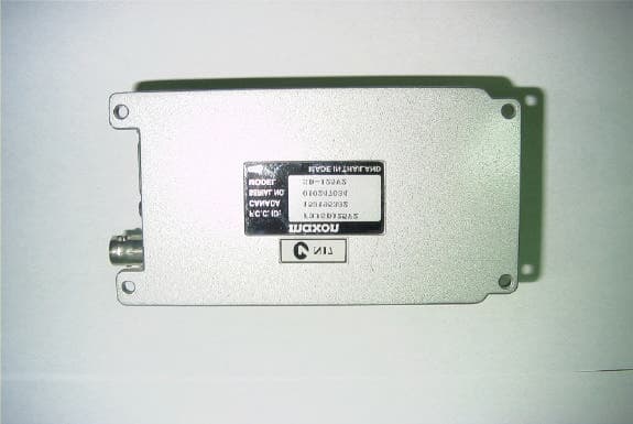
F3JSD125V3
Oct 09, 2002Data Radio
Equipment Class
TNB - Licensed Non-Broadcast Station Transmitter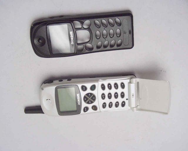
F3JMX1111
Feb 14, 2001800 MHz CDMA/AMPS Cellular Phone,Model MX-1111
Equipment Class
TNE - Licensed Non-Broadcast Transmitter Held to Ear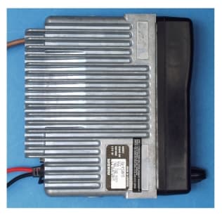
F3JSM6150V2
Sep 07, 2000VHF Mobile Transceiver
Equipment Class
TNB - Licensed Non-Broadcast Station Transmitter
F3JSP150V2
Aug 02, 2000Portable Transceiver
Equipment Class
TNB - Licensed Non-Broadcast Station Transmitter
F3JSM6450U6
Mar 20, 2000UHF mobile transceiver
Equipment Class
TNB - Licensed Non-Broadcast Station Transmitter