F3JSM6150V2VHF Mobile Transceiver
Midland Radio Corporation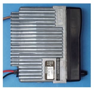
Click to zoom
Application Details
- Equipment Class
- TNB - Licensed Non-Broadcast Station Transmitter
- Date of Grant
- Sep 07, 2000
- Application Purpose
- Original Equipment
- Date of Application
- Sep 07, 2000
- Equipment Note
- VHF Mobile Transceiver
- Frequency Range
- 148.00000000 - 174.00000000
- Company
- Midland Radio Corporation
- Country
- United States
Documents & Files
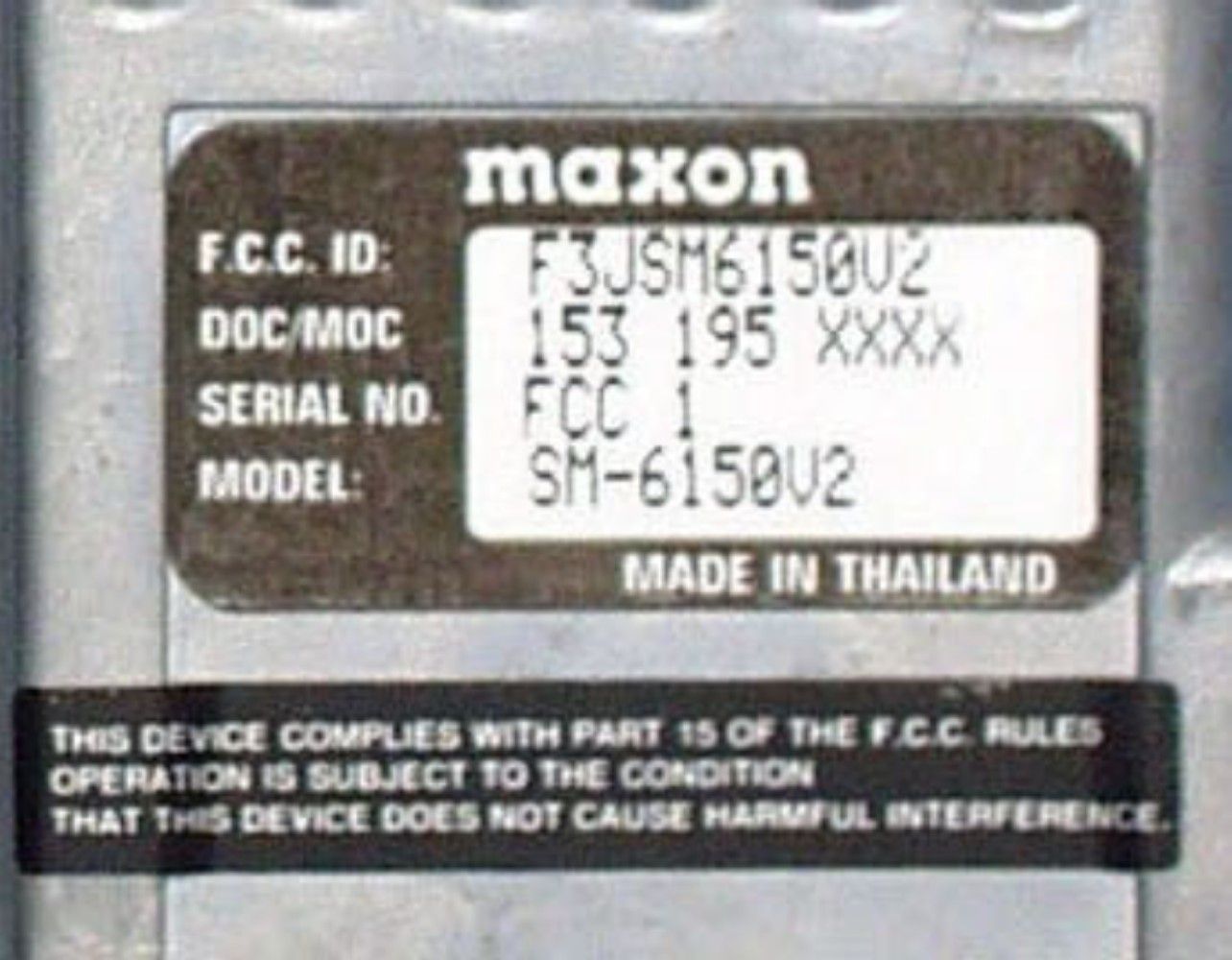
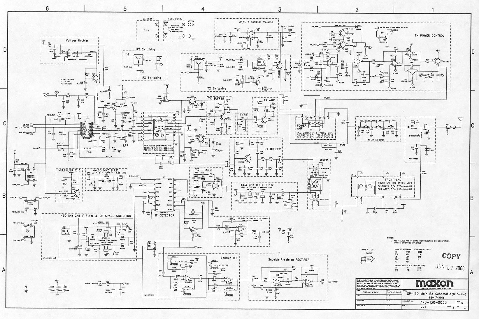
Document Text
Text extracted from the exhibit documents filed with the FCC. Open a document above to read the original.
Users Manual
1 SM-6000 Enduro series Operator’s Manualwritten by Gerald Happy About Your SM-6000 Enduro series Radio Maxon’s SM-6000 Enduro series mobile radio’s are compatible with LTR trunked systems and Conventional radio system operation. The SM-6000 Enduro series is capable of up to 200 Systems, 32 Groups per system LTR trunked operation, 16 Groups per system conventional operation. Operation and functions for Maxon’s SM-6000 Enduro series radios are described in this manual. We urge you to thoroughly read this manual before operating the radio. Application of some functions described in this manual is determined by the system you use. Your Maxon Dealer will program your radio so that you have the greatest number of functions possible relative to your needs. Should you have questions regarding the operation of the radio, please consult your Maxon Dealer. About Maxon America, Inc. Maxon America, Inc. designs and manufactures professional FM two-way radio equipment to serve a wide variety of communication needs. Maxon produces equipment for the Land Mobile Radio and Specialized Mobile Radio markets (business, industrial, government and public safety). Table of Contents Safety Information Unpacking Information SM-6000 Enduro series Features Installation Safeguards Description of radio Components Display Icons and Indications SM-6000 Enduro series Operation Power On/Off-Volume Trunked mode Operation Channel Monitoring System “Handshaking” Transmitting Receiving Transpond Mode Conventional mode Operation Transmitting Receiving Busy System Queuing Multiple Function Keypad Description Option Button Function Description Talk Around 2 Monitor Horn and Lights Auxiliary Public Address Status Indicators and Audible Alert Tones Scan Modes LTR Manual Group Scan LTR Auto Group Scan System Scan Conventional Group Scan Editing Scan List Conventional Scanning Normal Scan TX RX only/TX disable Priority Scan TX Priority only TX Priority Look Back Vacant Channel Scan Nuisance Delete ACC-703 DTMF Microphone Operation Auto Dial Operation Manual Dial Operation To Store a Number in Memory To Recall a Stored number from Memory Clearing a Stored Number Clearing a Dialed Number Licensing and Service Information Recycling/Disposal of Batteries Software Copyrights Maintenance Warranty Statement Safety Information The Federal Communications Commission (FCC), with its action in General Docket 93-62, November 7, 1997, has adopted a safety standard for human exposure to Radio Frequency (RF) electromagnetic energy emitted by FCC regulated equipment. Maxon subscribes to the same safety standard for the use of its products. Proper operation of this radio will result in user exposure far below the Occupational Safety and Health Act and Federal Communications Commission limits. Warning - It is mandatory that radio installations in vehicles fueled by liquefied petroleum gas conform to the following standard: National Fire Protection Association standard NFPA 58 applies to radio installations in vehicles fueled by liquefied petroleum (LP) gas with LP gas container in the trunk or other sealed-off space within the interior of the vehicle. This standard requires that: 1. Any space containing radio equipment shall be isolated by a seal from the space in which the LP gas container and its fittings are located. 2. Remote (outside) filling connections shall be vented to the outside. 3 Warning - DO NOT operate the transmitter of a mobile radio when someone outside the vehicle is within two feet (0.6 meter) of the antenna. Warning - DO NOT allow children to operate transmitter - equipped radio equipment. Caution - DO NOT operate the radio near electrical blasting caps or in an explosive atmosphere. Caution - DO NOT operate the transmitter of any radio unless all RF connectors are secure and any open connectors are properly terminated. All equipment must be properly grounded for safe operation. All equipment should be serviced by a qualified technician. Note: This radio operates in FCC regulated frequency bands. All radios must be licensed by the FCC before use. Because this radio contains a transmitter, Federal law prohibits unauthorized use or adjustments of this radio. This device complies with part 15 of the FCC rules. Operation is subject to the condition that this device does not cause harmful interference. Unpacking Information Remove and carefully inspect the contents of your package (s) for the following items: Radio Microphone DC Power Supply Cord Radio Mounting Bracket and Hardware Microphone Bracket and Hardware Operating Instructions If any items are missing, please contact your Dealer or Maxon. SM-6000 Enduro series Features • LTR Trunked radio operation • Conventional radio operation • 9 character display with icons • Wideband frequency separation • Programmable output power • Programmable 12.5/25 kHz channel spacing • Multiple-function five button keypad • Programmable On/Off hook function • Talk Around • Scanning • Priority Scanning 4 • Look Back • Scan list editing • CTCSS/CDDCS (Conventional operation) • Busy channel lockout • Time-out timer Installation Safeguards Warning - DO NOT install the unit where it would interfere with the proper operation of automatic collision protection devices (air bags). Warning - DO NOT install the unit where it would likely cause injury in case of accident. A. Select a location for the radio where you can easily see and reach all controls, including microphone. B. Using the radio mounting bracket as a template, mark the spots with a pencil where the bracket securing screws will be located. Note - Before drilling holes in the vehicle, verify that there is nothing that could be damaged or get in the way by drilling and putting screws in this location. It is better to use existing passages in the dashboard, trunk, and floor for the routing cable, thus avoiding excessive drilling. After drilling holes for the mounting bracket, attach bracket to surface using the two large Phillips head screws.…
Text truncated - open the document above for the full version.
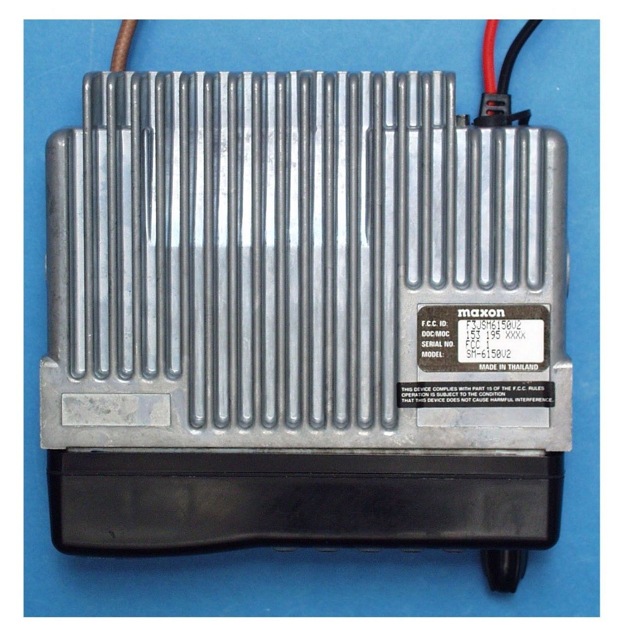
External Photos
Top View Right Side View Left Side View Botto m View Front View Back View
Operational Description
SM-6000 Enduro series Operations Power On/Off - Volume: Turn the radio on by rotating the On/Off - volume control clockwise until you hear a click and, if enabled via Dealer programming, the self test “alert” tone will be heard. SM- 6000 will briefly appear in the display. Turn the radio off by rotating the control counter clockwise. Trunked Mode Operation Your Maxon SM-6000 Enduro series may be programmed to operate with both Trunked and Conventional modes. There are only a few differences in their operation and these are detailed as follows. Channel Monitoring: While on a Trunked System, channel monitoring is performed automatically by the radio transceiver. In accordance with the FCC rules, while operating on a Conventional System the channel must be monitored prior to transmitting. In both Trunked and Conventional Systems, operation may vary from System to System. Your Maxon Dealer will be able to assist with particular operational parameters and procedures for the various Systems and functions. System “Handshaking” In a Trunked System, when the P-T-T is pressed on the microphone, a “Handshaking” routine occurs which establishes communications between the radio and Trunked System. When the LED indicator glows steadily red, voice transmission may begin. If your Maxon Dealer has enabled the “Clear to Talk” tone option, the radio will emit a short tone signaling voice transmission may occur. In Conventional Systems, there is no System “handshaking” and voice transmission may start immediately. Transmitting A. Rotate the On/Off - Volume control clockwise to turn the power on. B. Adjust On/Off - Volume control further clockwise to increase the volume level. Rotate counter clockwise to decrease volume level. C. Select the desired System and Group using the Up/Down buttons located on the front of the unit. D. Insure the microphone is secure in the Microphone jack located on the front of the unit, press and hold the P-T-T lever on the side of the Microphone.. E. Listen for the “Clear to Talk” tone (or wait for the LED indicator to glow steady red) and begin talking. Hold the microphone 1 or 2 inches from you mouth, speak clearly and distinctly into the microphone area of the front grille. F. Release the P-T-T lever as soon as the message is complete and listen for a response. The P-T-T lever must be pressed continuously while talking and released to listen. Receiving A. Turn power on and set the volume level as previously described. B. Select the desired System and System Group. C. When a message is received, the LED indicator will glow green. D. Respond to message by removing the microphone from hook, then press the P-T-T lever on the side of the microphone. Press the P-T-T continuously while talking and release to listen. If scanning modes are enabled be sure to respond before scanning resumes, if you do not, another call may be received and the selected System and Group may have to be changed. Scanning is indicated by scan mode icons. Refer to “Scan Modes” for more descriptive information. Transpond Mode If Transpond has been enabled by your Dealer, your radio will automatically send (transpond) an acknowledgment to the System indicating that your radio has received a transmission. Transpond is a Dealer programmable feature. Conventional Mode Operation Your Maxon SM-6000 Enduro series may be programmed to operate in Conventional modes. Conventional mode may or may not require a Conventional repeater System. Radio to radio communications can also be accomplished in Conventional operation. How the Conventional mode is programmed is determined by your Dealer. Transmitting A. Rotate the On/Off - Volume control clockwise to turn the power on. B. Adjust On/Off - Volume control further clockwise to increase the volume level. Rotate counter clockwise to decrease volume level. C. Select the desired Conventional System and Group channel using the Up/Down buttons located on the front panel of the radio. D. In a Conventional System it is necessary to monitor the channel for activity before a transmission. Monitor the channel by pressing the OPT (option) button located on the front panel and selecting monitor, once selected pressing OPT button once will begin monitor function, pressing OPT a second time will turn off monitor function. Monitoring of the channel can also be accomplished by observing the LED indicator for a solid yellow color. If solid yellow is observed, you must wait for the indication to leave before a transmission can be made. E. Press and hold the microphone P-T-T lever on the side of the microphone, LED indication will glow red, hold the microphone 1 or 2 inches from you mouth, speak clearly and distinctly into the microphone area of the front grille. F. Release the P-T-T lever as soon as the message is complete and listen for a response. The P-T-T lever must be pressed continuously while talking and released to listen. Receiving A. Turn power on and set the volume level as previously described. B. Select the desired System and System Group channel. C. When a message is received, the LED indicator will glow solid yellow or green depending if CTCSS tone or DCS has been programmed. D. Respond to message by pressing the P-T-T lever on the side of the microphone. Press the P-T-T continuously while talking and release to listen. If scanning modes are enabled be sure to respond before scanning resumes, if you do not, another call may be received and the selected channel may have to be changed. Scanning is indicated by the scan mode icons. Refer to “Conventional Scanning” for more descriptive information. Busy System Queuing If enabled by your Dealer, Busy System Queuing will monitor the System for activity. Once the System becomes available the System will automatically be accessed and held for a period of time, determined by your Dealer, allowing you to transmit on the System. An audible indication will sound along with a flashing yellow LED indication when queuing has begun and again w…
Text truncated - open the document above for the full version.
Parts List/Tune Up Info
ALIGNMENT PROCEDURE Alignment procedure when Dual VCO is mounted in a Radio. Rx VCO 1. Set the unit to the highest receive frequency, 174MHz and ADJUST L303 so the VCO control voltage at terminal 15 is set for 6.6Vdc (± 0. 1V). 2. Set the unit to the lowest receive frequency, 148MHz, then VERIFY that the VCO control voltage at terminal 15 is 1.OVdc or higher. Tx VCO 1. Set the unit to the highest transmit frequency, 174MHz and ADJUST L203 so the VCO control voltage at terminal 15 is set to 7.15 Vdc (± 0.1V). 2. Set the unit to the lowest transmit frequency, 148MHz, then VERIFY that the VCO control voltage at terminal 15 is 1.OVdc or higher. Alignment procedure when Dual VCO is mounted in the test fixture. Rx VCO 1. With the Rx VCO powered up at 4.5Vdc (+-O.1V) on VCO terminal 4, set the Control Voltage at terminal 15 to 6.6Vdc (± O.1V) and ADJUST L303 so the output frequency at VCO terminal 2 is 219.3MHz. (± 0.2MHz). 2. Set the Control Voltage to 1.OVdc (+-O. 1V) on VCO terminal 15. VERIFY that the frequency at terminal 2 is 193.3MHz or LOWER. Tx VCO 1. With the Tx VCO powered up at 4.5Vdc(± 0. 1 V) on terminal 8, set the Control Voltage at terminal 15 to 7.15Vdc ( +-O. 1 V) and ADJUST L203 so that the output frequency at VCO terminal 6 is 174MHz. (± 0.2MHz). 2. Set the Control Voltage to 1.OVdc(+-O. 1V) VCO terminal 15. VERIFY that the frequency at VCO terminal 6 is 148MHz or LOWER. VCO shield (E201) is to be installed and soldered to PCB prior to tuning VCO module. All tabs of shield to be soldered to FICB, comer seams to be sealed .
Test Report
ENGINEERING STATEMENT For Type Certification of MAXON AMERICA, INC. Model No: SM-6150-V2 FCC ID: F3JSM6150V2 I am an Electronics Engineer, a principal in the firm of Hyak Laboratories, Inc., Springfield, Virginia. My education and experience are a matter of record with the Federal Communications Commission. Hyak Laboratories, Inc. has been authorized by Maxon America, Inc. to make type certification measurements on the SM-6150-V2 transceiver. These tests made by me or under my supervision in our Springfield laboratory. Test data and documentation required by the FCC for Type Certification are included in this report. The data verifies that the above mentioned transceiver meets FCC requirements and Type Certification is requested. ______________________________ Rowland S. Johnson Dated: June 30, 2000 A. INTRODUCTION The following data are submitted in connection with this request for Type Certification of the SM-6150-V2 transceiver in accordance with Part 2, Subpart J of the FCC Rules. The SM-6150-V2 is a multi-bandwidth, VHF, frequency modulated transceiver intended for vehicular mobile applications in the 148 - 174 MHz band. It operates from a nominal 13.8 volt supply. Output power rating is 10-45 watts. Both 25 kHz and 12.5 kHz channel operation is provided. B. GENERAL INFORMATION REQUIRED FOR TYPE CERTIFICATION (Paragraph 2.983 of the Rules) 1. Name of applicant: Maxon America, Inc. 2. Identification of equipment: F3JSM6150V2 a. The equipment identification label is submitted as a separate exhibit. b. Photographs of the equipment are submitted as a separate exhibit. 3. Quantity production is planned. 4. Technical description: a. 16k0F3E; 11k0F3E emission b. Frequency range: 148-174 MHz. c. Operating power of transmitter is fixed at the factory at 45 watts and can be reduced to 10 watts. d. Maximum power permitted under Part 90 of the FCC is 350 watts, and the SM-6150-V2 fully complied with those power limitations. e. The dc voltage and dc currents at final amplifier: Collector voltage: 13.6 Vdc Collector current: 6.5 A f. Function of each active semiconductor device: See Appendix 1. g. Complete circuit diagram is submitted as a separate exhibit. h. A draft instruction book is submitted as a separate exhibit. i. The transmitter tune-up procedure is submitted as a separate exhibit. j. A description of circuits for stabilizing frequency is included in Appendix 2. 2 B. GENERAL INFORMATION... (Continued) k. A description of circuits and devices employed for suppression of spurious radiation and for limiting modulation is included in Appendix 3. l. Not applicable. 5. Data for 2.985 through 2.997 follow this section. C. RF POWER OUTPUT (Paragraph 2.985(a) of the Rules) RF power output was measured with a Bird 4421 RF power meter and a Narda 765-20 attenuator as a 50 ohm dummy load. Maximum power measured was 45 watts; and with internal adjustments minimum power was 10 watts. (The transmitter was tuned by the factory.) D. MODULATION CHARACTERISTICS 1. A curve showing frequency response of the transmitter is shown in Figure 1. Reference level was audio signal output from a Boonton 8220 modulation meter with one kHz deviation. Audio output was measured with a Audio Precision System One TRMS voltmeter and tracking generator. 2. Modulation limiting curves are shown in Figures 2a and 2b for wide or narrow channel operation respectively, using a Boonton 8220 modulation meter. Signal level was established with a Audio Precision System One TRMS voltmeter. The curves show compliance with paragraphs 2.987(b), and 90.211(c). 3. Figure 3 is a graph of the post-limiter low pass filter which meets the requirements of paragraph 90.211(d)(1) in providing a roll-off of 60Logf/3 dB where f is audio frequency in kHz. Measurements were made following EIA RS-152B with an Audio Precision System One selective voltmeter on the Boonton 8220 modulation meter audio output. 3 D. MODULATION CHARACTERISTICS (Continued) 4. Occupied_Bandwidth (Paragraphs 2.989(c), 90.209(b)(4) and 90.210(d) of the Rules) Figures 4a, 4b, 4c and 4d are plots of the sideband envelope of the transmitter for both 45 and 10 watt output taken with a Advantest R3361A spectrum analyzer. Modulation corresponded to conditions of 2.989(c)(1) and consisted of 2500 Hz tone at an input level 16 dB greater than that necessary to produce 50% modulation at 2476 Hz, the frequency of maximum response. Measured modulation under these conditions was 3.8 kHz, or 1.9 kHz for 25 or 12.5 kHz channelization respectively. For the 12.5 kHz channelization, RBW was 100 Hz, VBW 100 Hz, max hold, multiple scan per 90.210(d)(4). All plots have unmodulated carrier as 0 dBm reference. 4 FIGURE 1 MODULATION FREQUENCY RESPONSE MODULATION FREQUENCY RESPONSE FCC ID: F3JSM6150V2 FIGURE 1 5 FIGURE 2a AUDIO LIMITER CHARACTERISTICS AUDIO LIMITER CHARACTERISTICS FCC ID: F3JSM6150V2 FIGURE 2a Wideband (5 kHz) 6 FIGURE 2b AUDIO LIMITER CHARACTERISTICS AUDIO LIMITER CHARACTERISTICS FCC ID: F3JSM6150V2 FIGURE 2b Narrow band (2.5 kHz) 7 FIGURE 3 AUDIO LOW PASS FILTER RESPONSE AUDIO LOW PASS FILTER RESPONSE FCC ID: F3JSM6150V2 FIGURE 3 8 FIGURE 4a OCCUPIED BANDWIDTH ATTENUATION IN dB BELOW MEAN OUTPUT POWER Required On any frequency more than 50% up to and including 100% of the 25 authorized bandwidth, 20 kHz (10-20 kHz) On any frequency more than 100%, up to and including 250% of the 35 authorized bandwidth (20-50 kHz) On any frequency removed from the assigned frequency by more 43+10LogP = 60 than 250% of the authorized (P = 45 W) bandwidth (over 50 kHz) OCCUPIED BANDWIDTH (45 W) FCC ID: F3JSM6150V2 FIGURE 4a (5 kHz) 9 FIGURE 4b OCCUPIED BANDWIDTH ATTENUATION IN dB BELOW MEAN OUTPUT POWER Required On any frequency more than 50% up to and including 100% of the 25 authorized bandwidth, 20 kHz (10-20 kHz) On any frequency more than 100%, up to and including 250% of the 35 authorized bandwidth (20-50 kHz) On any frequency removed from the assigned frequency by more 43+10LogP = 53 than 250% of…
Text truncated - open the document above for the full version.
Contact Information
Applicant
Jeff Brame(Director of Engineering)
Technical Specifications
| # | Rule Parts | Frequency Range | Power Output | Emission | Tolerance |
|---|---|---|---|---|---|
| 2 | 22,74,9 | 148 MHz - 174 MHz | 45 W | 11K0F3E | 0.00025 % |
Other Applications from Midland Radio Corporation
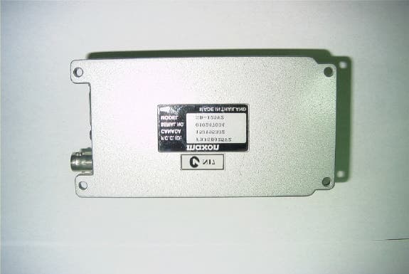
F3JSD125V3
Oct 09, 2002Data Radio
Equipment Class
TNB - Licensed Non-Broadcast Station Transmitter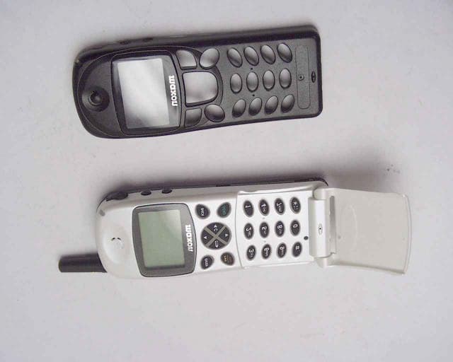
F3JMX1111
Feb 14, 2001800 MHz CDMA/AMPS Cellular Phone,Model MX-1111
Equipment Class
TNE - Licensed Non-Broadcast Transmitter Held to Ear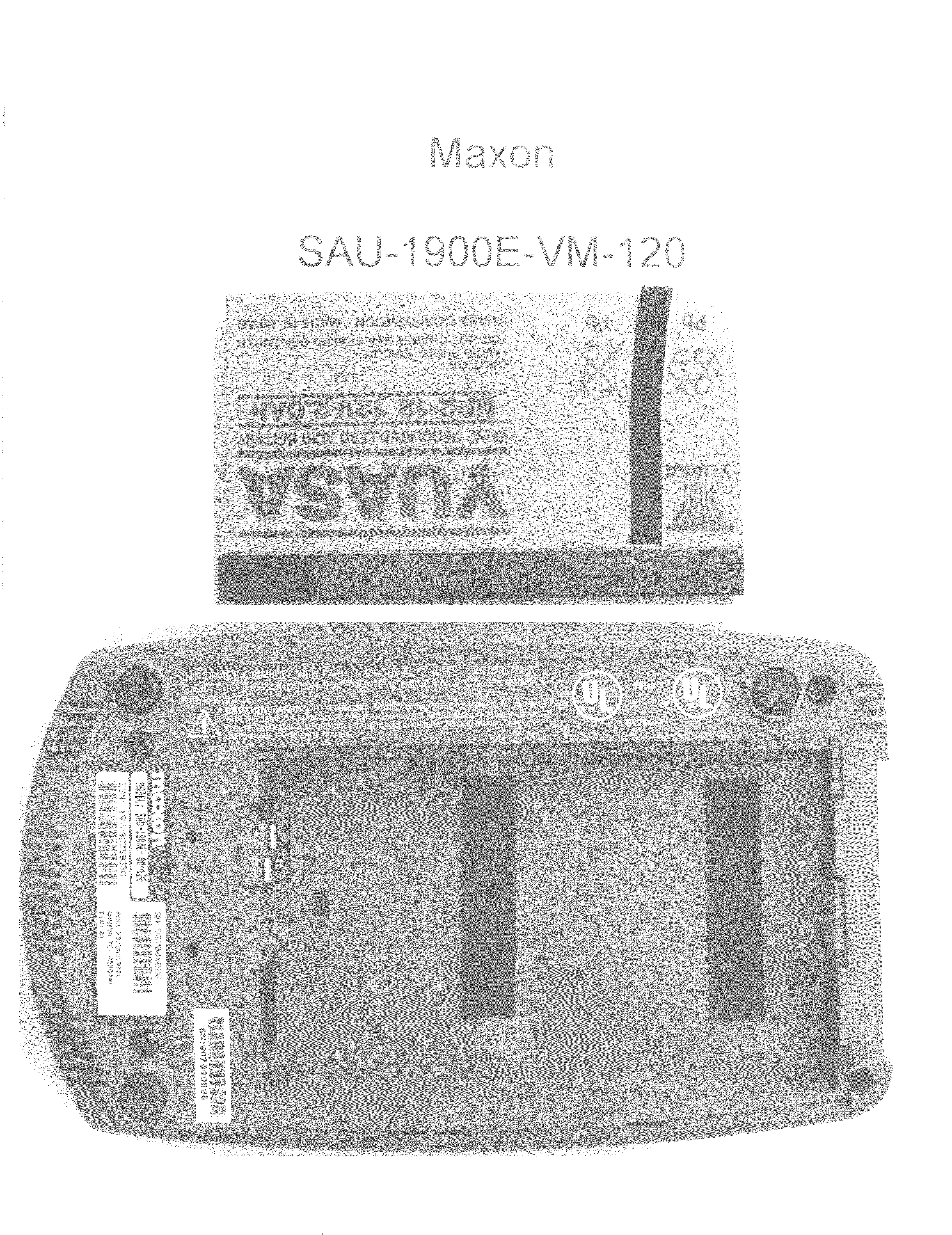
F3JSAU1900E
Aug 02, 2000PCS Band CDMA Wireless Local Loop Transceiver
Equipment Class
TNB - Licensed Non-Broadcast Station Transmitter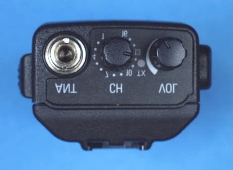
F3JSP150V2
Aug 02, 2000Portable Transceiver
Equipment Class
TNB - Licensed Non-Broadcast Station Transmitter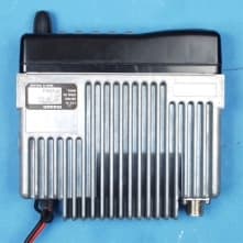
F3JSM6450U6
Mar 20, 2000UHF mobile transceiver
Equipment Class
TNB - Licensed Non-Broadcast Station Transmitter